
PS 6048 - Charger RCF - Free user manual and instructions
Find the device manual for free PS 6048 RCF in PDF.


| Product Type | Battery Charger / Power Supply |
| Brand | RCF |
| Model | PS 6048 |
| Input Voltage | 100-240 V AC, 50/60 Hz |
| Output Voltage | 48 V DC |
| Output Current | 6 A |
| Max Power | 288 W |
| Charging Mode | Constant current / constant voltage (CC/CV) |
| Protection Features | Overload, short circuit, overvoltage, overcurrent, over temperature |
| LED Indicators | Power on, charging status, fault |
| Operating Temperature | 0°C to 40°C |
| Storage Temperature | -20°C to 60°C |
| Dimensions (W x H x D) | 200 x 85 x 150 mm |
| Weight | 1.2 kg |
| Housing Material | Metal with ventilation grilles |
| Cooling | Natural convection |
| Certifications | CE, RoHS |
| Compatible Battery Types | Lead-acid (AGM, Gel, Flooded) or Lithium (if supported) |
| Charging Algorithm | Multi-stage for optimal battery life |
| AC Input Connector | IEC C14 |
| DC Output Connector | Anderson Powerpole or screw terminals |
Frequently Asked Questions - PS 6048 RCF
User questions about PS 6048 RCF
0 question about this device. Answer the ones you know or ask your own.
Ask a new question about this device
Download the instructions for your Charger in PDF format for free! Find your manual PS 6048 - RCF and take your electronic device back in hand. On this page are published all the documents necessary for the use of your device. PS 6048 by RCF.
USER MANUAL PS 6048 RCF
USER MANUAL MANUALE D'USO
PS 6048
- BACKUP POWER SUPPLY UNIT AND BATTERY CHARGER
- ALIMENTATORE D'EMERGENZA CARICABATTERIE
TABLE OF CONTENTS INDICE

ENGLISH
SAFETY PRECAUTIONS 4
DESCRIPTION 6
INSTALLATION 6
INTERNAL JUMPER SETTING AND BATTERIES 6
BLOCK DIAGRAM 8
BATTERY WIRING INSTRUCTIONS 9
Before connecting and using this product, please read this instruction manual carefully and keep it on hand for future reference.
The manual is to be considered an integral part of this product and must accompany it when it changes ownership as a reference for correct installation and use as well as for the safety precautions.
RCF S.p.A. will not assume any responsibility for the incorrect installation and / or use of this product.
WARNING: To prevent the risk of fire or electric shock, never expose this product to rain or humidity.
SAFETY PRECAUTIONS
- All the precautions, in particular the safety ones, must be read with special attention, as they provide important information.
2.1 POWER SUPPLY FROM MAINS
- The mains voltage is sufficiently high to involve a risk of electrocution: never install or connect this product when its power cord is plugged in.
- Before powering up, make sure that all the connections have been made correctly and the voltage of your mains corresponds to the voltage shown on the rating plate on the unit, if not, please contact your RCF dealer.
- The metallic parts of the unit are earthed by means of the power cord.
- An apparatus with CLASS I construction shall be connected to a mains socket outlet with a protective earthing connection.
- Protect the power cord from damage. Make sure it is positioned in a way that it cannot be stepped on or crushed by objects.
- To prevent the risk of electric shock, never open this product: there are no parts inside that the user needs to access.
- The mains plug is used as the disconnect device and it shall remain readily operable.
2.2 BATTERIES
- Operating voltage is 48 V dc (therefore, it is necessary to connect in series several batteries having a lower nominal voltage, example: 4 x 12 V).
- Always use rechargeable batteries, which need to be chosen according to the maximum possible load.
- Verify the polarity of batteries is correct.
- Do NOT short-circuit batteries (i.e. connecting the 2 opposite poles together with metallic wires).
-
Throw empty batteries away according to your country laws about ecology and environment protection.
-
Make sure that no objects or liquids can get into this product, as this may cause a short circuit.
This apparatus shall not be exposed to dripping or splashing.
No objects filled with liquid (such as vases) and no naked sources (such as lighted candles) shall be placed on this apparatus.
IMPORTANT


- Never attempt to carry out any operations, modifications or repairs that are not expressly described in this manual.
Contact your authorized service centre or qualified personnel should any of the following occur:
- The product does not function (or functions in an anomalous way).
- The power cord has been damaged.
- Objects or liquids have got in the unit.
-
The product has been subject to a heavy impact.
-
If this product is not used for a long period, disconnect both the power cord and batteries.
-
If this product begins emitting any strange odours or smoke, switch it off immediately and disconnect both the power cord and batteries.
-
Do not connect this product to any equipment or accessories not foreseen.
For suspended installation, only use the dedicated anchoring points and do not try to hang this product by using elements that are unsuitable or not specific for this purpose. Also check the suitability of the support surface to which the product is anchored (wall, ceiling, structure, etc.), and the components used for attachment (screw anchors, screws, brackets not supplied by RCF etc.), which must guarantee the security of the system / installation over time, also considering, for example, the mechanical vibrations normally generated by transducers.
To prevent the risk of falling equipment, do not stack multiple units of this product unless this possibility is specified in the user manual.
- RCF S.p.A. strongly recommends this product is only installed by professional qualified installers (or specialised firms) who can ensure correct installation and certify it according to the regulations in force.
The entire audio system must comply with the current standards and regulations regarding electrical systems.
- Supports and trolleys
The equipment should be only used on trolleys or supports, where necessary, that are recommended by the manufacturer. The equipment / support / trolley assembly must be moved with extreme caution. Sudden stops, excessive pushing force and uneven floors may cause the assembly to overturn.
- Do not obstruct the ventilation grilles of the unit. Situate this product far from any heat sources and always ensure adequate air circulation around the ventilation grilles.
- Do not use solvents, alcohol, benzene or other volatile substances for cleaning the external parts of this product. Use a dry cloth.
RCF S.P.A. THANKS YOU FOR PURCHASING THIS PRODUCT, WHICH HAS BEEN DESIGNED TO GUARANTEE RELIABILITY AND HIGH PERFORMANCES.
DESCRIPTION

PS 6048 is a backup power supply unit suitable to get continuity power supply for EN 54-16 system units (e.g. DXT 9000 and DXT 7000EN systems).
PS 6048 needs to be equipped with lead-acid batteries and includes recharging and monitoring functions.
INSTALLATION

Fix the unit to a 19" rack cabinet through 4 screws.
According to EN 54-16 standard, the backup power supply unit shall be installed into the same rack cabinet where there is the audio system with emergency purposes (or a system part) to which it is connected.
19" rack - 2U

natural_image
Technical diagram of a server rack with mounting flanges and a central panel (no text or symbols)INTERNAL JUMPER SETTING AND BATTERIES

IMPORTANTE: INTERNAL JUMPER SETTING SHALL BE CARRIED OUT ONLY BY EITHER RCF OR AN AUTHORISED SERVICE CENTRE.
In normal operating mode: the PS 6048 recharges batteries (and maintains them when they are fully charged).
The maximum total output current that can be supplied continuously (I max a) while charging batteries is given by:
$$ I \max a = I n - \frac {C}{2 0} $$
I n: nominal output current (12 A)
C: battery capacity [A h]
When the mains supply is available, the maximum total output current that can be supplied for a short period of time (1 max b) corresponds to the nominal value (12 A). During this time, batteries are not charged (nor discharged).
$$ I \max b = I n $$
When the mains supply is NOT available (backup operating mode), the maximum total output current that can be supplied from batteries (I max c) is either 150 A if the internal jumper is set to '75' or 100 A if set to '50'.
$$ I m a x c = 1 5 0 A / 1 0 0 A $$
a) I max c = 150 A
Set the internal jumper to '75' and use batteries with a capacity of 86 to 225 Ah.
b) I max c = 100 A
Set the internal jumper to '50' and use batteries with a capacity of 65 to 225 Ah.
The jumper factory setting is the '75' position. Any other jumper setting is like the '50' position.

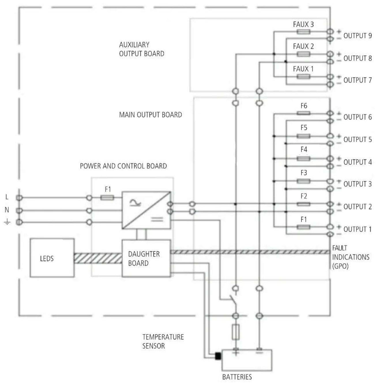
flowchart
graph TD
    A["AUXILIARY OUTPUT BOARD"] --> B["FAUX 3"]
    A --> C["FAUX 2"]
    A --> D["FAUX 1"]
    B --> E["OUTPUT 9"]
    C --> F["OUTPUT 8"]
    D --> G["OUTPUT 7"]
    H["MAIN OUTPUT BOARD"] --> I["F6"]
    H --> J["F5"]
    H --> K["F4"]
    H --> L["F3"]
    I --> M["OUTPUT 6"]
    J --> N["OUTPUT 5"]
    K --> O["OUTPUT 4"]
    L --> P["OUTPUT 3"]
    Q["POWER AND CONTROL BOARD"] --> R["F1"]
    S["LEDS"] --> T["DAUGHTER BOARD"]
    U["TEMPERATURE SENSOR"] --> V["BATTERIES"]
    W["FAULT INDICATIONS (GPO)"] --> X["F1"]
    Y["BATTERIES"] --> Z["F2"]
APPROVED BATTERY MODELS:
- Yuasa NPL series
- Powersonic GB series
- ABT TM series
- Enersys VE series
- Effekta BTL series
- Long GB series.
It is advised to secure batteries with a (low resistance, gG curve) fuse, chosen according to maximum current.
The battery temperature sensor shall be placed as close as possible to batteries, but it does not need to be in contact with them. For example, it may be fixed on the battery cables.
The PS 6640 checks the battery resistance (including connections) every 4 hours.
The fault threshold resistance value is either 32 m ± 10% if the jumper is set to the '75' position or 48 m ± 10% if set to the '50' position. Exceeding this threshold is signaled as a battery fault: batteries will not have the required backup duration in case of mains power cut.
To avoid possible false fault indications, use battery cables as short as possible and with large cross sections (35 mm ^2 max).
Approximately, the resistance per metre of a cable (with two copper wires) is:
- 3.6 mΩ/m (10 mm² section)
- 2.3 mΩ/m (16 mm² section)
- 1.5 mΩ/m (25 mm² section)
- 1.1 mΩ/m (35 mm² section).
EXAMPLE: THE RESISTANCE VALUE OF A 1.5 M CABLE WITH A 10 MM ^2 CROSS-SECTION IS 5.4 MΩ.
1.5M CABLES WITH A 25 MM ^2 CROSS-SECTION ALLOW CORRECT OPERATION WITH ALL RECOMMENDED BATTERIES. THE BATTERY FUSE ADDS ABOUT 1 TO 2 MΩ. THE CONNECTIONS AND CRIMPING SHOULD BE REALIZED PROPERLY IN ORDER TO GET THE LOWEST RESISTANCE AS POSSIBLE.

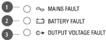
The MAINS FAULT ^1 is indicated when the front panel LED turns from green to yellow and remotely by its respective (5 s) delayed dry contact (fail-safe, for remote monitoring) when:
- The mains is not present or lower than either 185 V ac ±5% (if the charger is not recharging) or 165 V ac ±5% (if the charger is recharging).
- The mains fuse is blown or not present.
- The charger is faulty.
- The internal temperature is too high.
Green LED: OK (no mains fault).
The BATTERY FAULT ^2 is indicated when the front panel LED turns from green to yellow and remotely by its respective dry contact (fail-safe, for remote monitoring) when:
- Batteries are not present (the battery test is carried out in this way: every 30 seconds for the first 20 minutes after commissioning and then every 15 minutes; if a fault is detected, batteries will have been tested every 30 seconds for 20 minutes after the fault disappears).
- The battery internal resistance is too high (a test occurs every 4 hours when the mains supply is present and the charger output current is lower than 12A; the resistance limit value is 32m ± 10% ).
- The battery voltage is lower than 47 V ±3% (when the mains supply is present).
A voltage compensation system maintains the charge characteristics within the battery limits across the entire operational temperature range.
THE BATTERY LOW VOLTAGE PROTECTION THRESHOLD IS 43.2 V ±3 %. WHEN THE BATTERY VOLTAGE REACHES THE PROTECTION THRESHOLD, A RELAY DISCONNECTS BATTERIES FROM MAIN AND AUXILIARY OUTPUTS.
Protection from battery reverse connection:
- At start-up, the battery relay will not let the current pass.
- During operation: the F8 fuse will blow out.
If the battery voltage is either higher than 60 V ± 3% or lower than 40 V ± 3% , batteries will not be connected.
Green LED: OK (no battery fault).
The OUTPUT VOLTAGE FAULT ^3 is indicated when the front panel LED turns from green to yellow and remotely by its respective dry contact (fail-safe, for remote monitoring) if there is no output voltage on one or more outputs (all nine outputs are checked).
Green LED: OK (no output voltage fault).


4 Six (1 to 6) main 48 V dc outputs (to amplifiers).
Connectors: lockable screw terminals (max. wire section: 16 mm ^4 ).
5 Three (7, 8, 9) auxiliary 48 V dc outputs.
Connectors: screw terminals (max. wire section: 2.5 mm ^4 ).
6 Logic outputs for remote fault monitoring.
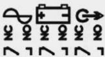
From left to right:
MAINS FAULT, BATTERY FAULT, OUTPUT VOLTAGE FAULT.
Connectors: screw terminals (max. wire section: 1.5 mm ^4 ).
Each logic output has three dry contacts: normally closed (NC), common and normally open (NO).
Fault indications can be obtained by connecting these contacts to logic inputs of the control device.
The max. current is either 1 A at 24 V dc or 0.5 A at 120 V ac.
7 Input for the mains power cord plug (lockable, IEC320, 2.5mm ^4 wire section).
8 Input for the battery temperature sensor.
9 48 V dc input (for battery connection).
Connector: screw terminals (max. wire section: 50 mm ^4 ).
Four 12 V batteries need to be linked in series (total voltage: 48 V dc).


6

7

8
9
WIRING
a. Connect the battery cable to the PS 6048 48 V dc input 9, but do NOT connect the battery terminals.
b. After connecting the mains power cord and all loads, turn on the mains supply (switch on the circuit-breaker upstream).
c. Check the output voltage to loads.
d. Connect the battery terminals.
The PS 6048 properly operates when all its three front panel LEDs are lit and green.
IMPORTANT: IF AMPLIFIERS ARE NOT POWERED BY THE SAME MAINS LINKED TO THE PS 6048, AN AMPLIFIER MAINS FAILURE MUST GENERATE AN ALARM TO THE VOICE ALARM SYSTEM.
DIODE INSERTION TO LINK MU 7100EN (DXT 7000EN)

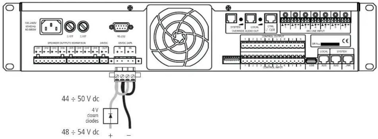
The MU 7100EN (DXT 7000EN main unit) 48VDC input shall be connected to a PS 6048 through diodes that are needed to get a 4 V voltage drop.
MAINTENANCE

In order to ensure maximal and durable service, this product needs to be installed in a dry and ventilated location and maintained clean. RCF S.p.A. is in no case liable for damages associated with improper use or incorrect maintenance of the equipment.
WARNING: do NOT use an incorrect type of batteries, as this may result in an explosion hazard.
Used batteries must be disposed of in compliance with recycling requirements.
NO OUTPUT VOLTAGE:
- Check the mains supply presence
- Check fuses (RCF service only)
- Check each single output voltage
- Check that each 12 V dc battery has a voltage equal or higher than 11.5 V dc
- Repeat measurements after having disconnected loads and batteries
- Check the front panel LED indications
- If all the previous steps are validated, check the load compatibility
THE BATTERY FAULT LED IS LIT YELLOW:
- Check if the battery voltage is in the 40 ÷ 60 V range
- Check the battery wiring and polarity
BATTERIES DO NOT TAKE OVER AFTER A MAINS FAULT:
- Check the voltage of each single battery
- Check the battery link and fuse
- Check the voltage on each single output
IF THE FRONT PANEL LED ARE NOT LIT:
- Check the mains supply presence
- Check the battery link and fuse
- Check the voltage on each single output
- Check the internal flat cable (RCF service only)
SPECIFICATIONS

RATED OUTPUT VOLTAGE:
OUTPUT VOLTAGE AT HALF LOAD (25°C):
MAX. TOTAL POWER (ALL THE 9 OUTPUTS):
MAX. TOTAL OUTPUT CURRENT (ALL THE 9 OUTPUTS):
MAIN 48 V DC OUTPUTS (TO AMPLIFIERS):
MAX. POWER PER EACH MAIN OUTPUT:
MAX. CURRENT PER EACH MAIN OUTPUT:
AUXILIARY 48 V DC OUTPUTS:
MAX. POWER PER EACH AUXILIARY OUTPUT:
MAX. CURRENT PER EACH AUXILIARY OUTPUT:
CHARGER RATED OUTPUT CURRENT:
OPERATING TEMPERATURE:
OPERATING RELATIVE HUMIDITY:
INTERNAL TEMPERATURE, PROTECTION THRESHOLD:
STORAGE TEMPERATURE:
7200 W (internal jumper set to '75')
4800 W (internal jumper set to '50')
150 A (internal jumper set to '75')
100 A (internal jumper set to '50')
6 (from 1 to 6)
1536 W
32 A
3 (from 7 to 9)
240 W
5 A
12 A
-5 ÷ +45 °C (23 ÷ 113 °F) at 12 A
20 ÷ 95 % without condensation
+65°C (149 °F)
-25 ÷ +85^ (-13 ÷ +185^)
230 V ac ±15% (47 ÷ 63 Hz), class I
4 A
760 W
48 V dc (four 12 V batteries linked in series)
86 ÷ 225 Ah (internal jumper set to '75')
65 ÷ 225 Ah (internal jumper set to '50')
19", 2U rack
344 mm deep without connectors
399 mm deep with connectors
5.9 kg (13 lbs)
0333-CPR-075383-2, 2011
EN 54-4 (1997) + A1 (2002) + A2 (2006)
FUSES

MOTHER BOARD F1 (MAINS):
MOTHER BOARD F8:
MAIN OUTPUT BOARD F1 TO F6 (6 OUTPUTS):
AUXILIARY OUTPUT BOARD FAUX1-2-3 (3 OUTPUTS):
EXTERNAL BATTERY FUSE (NOT INCLUDED):
T8A 5x20 250V (breaking capacity: 1500 A)
T12.5A 5x20
32 A gG 10x38
F5A 5x20
choose a gG curve fuse according to the battery maximum current (e.g. 80/100/125 A)
AVVERTENZEPERLASICUREZZA
DESCRIZIONE
INSTALLAZIONE
IMPOSTAZIONE DEL JUMPER INTERNO E BATTERIE
SCHEMA A BLOCCHI
ISTRUZIONI PER IL CABLAGGIO DELLE BATTERIE
LED SUL PANNELLO FRONTALE E FUNZIONAMENTO
PANNELLO POSTERIORE E CABLAGGIO
MANUTENZIONE
natural_image
Technical diagram of a server rack with mounting flanges and a central panel (no text or symbols)IMPOSTAZIONE DEL JUMPER INTERNO E BATTERIE

IMPORTANTE: L'IMPOSTAZIONE DEL JUMPER INTERNO DEVE ESSERE EFFETTUATA SOLO DA RCF OPPURE DA UN CENTRO ASSISTENZA AUTORIZZATO.
$$ I \max a = I n - \frac {C}{2 0} $$
I n: corrente nominale d'uscita (12 A)
$$ I \max b = I n $$
$$ I \max c = 1 5 0 A / 1 0 0 A $$
a) I max c = 150 A
NESSUNA TENSIONE DI USCITA:
TENSIONE NOMINALE D'USCITA:
TENSIONE D'USCITA CON MEZZO CARICO (25°C):
MAX. POTENZA TOTALE (TUTTE LE 9 USCITE):
MAX. CORRENTE D'USCITA TOTALE (TUTTE LE 9 USCITE):
USCITE PRINCIPALI 48 V C.C. (PER AMPLIFICATORI):
MAX. POTENZA PER CIASCUNA USCITA PRINCIPALE:
MAX. CORRENTE PER CIASCUNA USCITA PRINCIPALE:
USCITE AUSILIARIE 48 V C.C.:
MAX. POTENZA PER CIASCUNA USCITA AUSILIARIA:
MAX. CORRENTE PER CIASCUNA USCITA AUSILIARIA:
CORRENTE D'USCITA NOMINALE DEL CARICABATTERIE:
SCHEDA USCITE PRINCIPALI F1÷F6 (6 USCITE):
SCHEDA USCITE AUSILIARIE FAUX1-2-3 (3 USCITE):
FUSIBILE ESTERNO PROTEZIONE BATTERIE (NON INCLUSO):
Except possible errors and omissions.
RCF S.p.A. reserves the right to make modifications without prior notice.
Manufactured by SLAT - 180130015Ca - NOT130010Ca - Ed 03/15

- USER MANUAL MANUALE D'USO
- TABLE OF CONTENTS INDICE
- ENGLISH
- SAFETY PRECAUTIONS
- POWER SUPPLY FROM MAINS
- BATTERIES
- IMPORTANT
- DESCRIPTION
- INSTALLATION
- INTERNAL JUMPER SETTING AND BATTERIES
- APPROVED BATTERY MODELS:
- WIRING
- DIODE INSERTION TO LINK MU 7100EN (DXT 7000EN)
- MAINTENANCE
- NO OUTPUT VOLTAGE:
- THE BATTERY FAULT LED IS LIT YELLOW:
- BATTERIES DO NOT TAKE OVER AFTER A MAINS FAULT:
- IF THE FRONT PANEL LED ARE NOT LIT:
- SPECIFICATIONS
- RATED OUTPUT VOLTAGE:
- OUTPUT VOLTAGE AT HALF LOAD (25°C):
- MAIN 48 V DC OUTPUTS (TO AMPLIFIERS):
- AUXILIARY 48 V DC OUTPUTS:
- OPERATING TEMPERATURE:
- AVVERTENZEPERLASICUREZZA
- IMPOSTAZIONE DEL JUMPER INTERNO E BATTERIE
- a) I max c = 150 A
- NESSUNA TENSIONE DI USCITA:
Brand : RCF
Model : PS 6048
Category : Charger