DTW251RTJ - Screwdriver MAKITA - Free user manual and instructions
Find the device manual for free DTW251RTJ MAKITA in PDF.
Download the instructions for your Screwdriver in PDF format for free! Find your manual DTW251RTJ - MAKITA and take your electronic device back in hand. On this page are published all the documents necessary for the use of your device. DTW251RTJ by MAKITA.
USER MANUAL DTW251RTJ MAKITA
Cordless Impact Wrench Instruction Manual
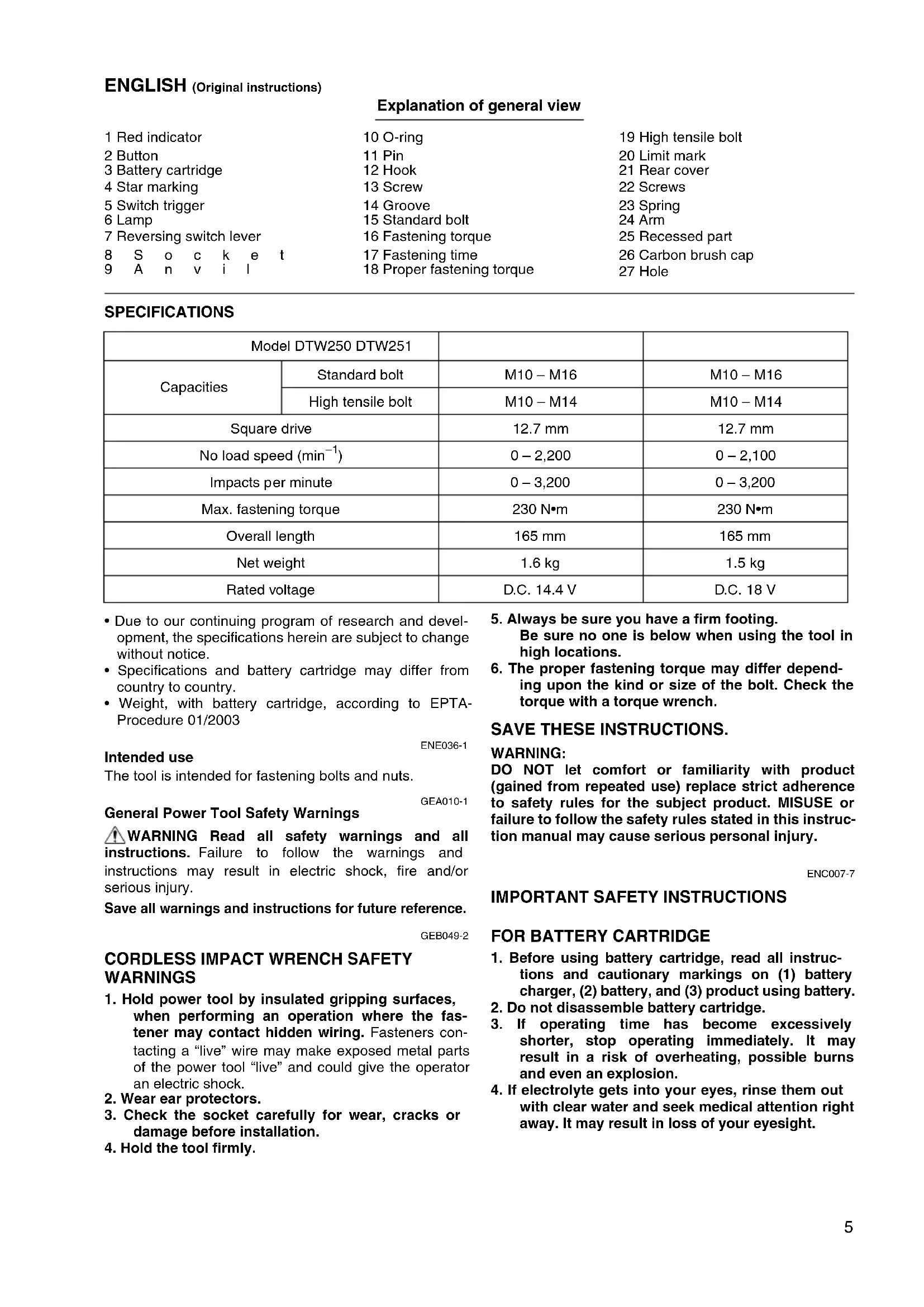
- Due to our continuing program of research and devel- opment, the specifications herein are subject to change without notice.
- Specifications and battery cartridge may differ from country to country.
- Weight, with battery cartridge, according to EPTA- Procedure 01/2003 ENE036-1 Intended use The tool is intended for fastening bolts and nuts. GEA010-1 General Power Tool Safety Warnings WARNING Read all safety warnings and all instructions. Failure to follow the warnings and instructions may result in electric shock, fire and/or serious injury. Save all warnings and instructions for future reference. GEB049-2
CORDLESS IMPACT WRENCH SAFETY
1. Hold power tool by insulated gripping surfaces,
when performing an operation where the fas- tener may contact hidden wiring. Fasteners con- tacting a “live” wire may make exposed metal parts of the power tool “live” and could give the operator an electric shock.
2. Wear ear protectors.
3. Check the socket carefully for wear, cracks or
damage before installation.
4. Hold the tool firmly.
5. Always be sure you have a firm footing.
Be sure no one is below when using the tool in high locations.
6. The proper fastening torque may differ depend-
ing upon the kind or size of the bolt. Check the torque with a torque wrench. SAVE THESE INSTRUCTIONS.
DO NOT let comfort or familiarity with product (gained from repeated use) replace strict adherence to safety rules for the subject product. MISUSE or failure to follow the safety rules stated in this instruc- tion manual may cause serious personal injury. ENC007-7
1. Before using battery cartridge, read all instruc-
tions and cautionary markings on (1) battery charger, (2) battery, and (3) product using battery.
2. Do not disassemble battery cartridge.
3. If operating time has become excessively
shorter, stop operating immediately. It may result in a risk of overheating, possible burns and even an explosion.
4. If electrolyte gets into your eyes, rinse them out
with clear water and seek medical attention right away. It may result in loss of your eyesight. Model DTW250 DTW251 Capacities Standard bolt M10 – M16 M10 – M16 High tensile bolt M10 – M14 M10 – M14 Square drive 12.7 mm 12.7 mm No load speed (min
5. Do not short the battery cartridge:
(1) Do not touch the terminals with any conduc- tive material. (2) Avoid storing battery cartridge in a container with other metal objects such as nails, coins, etc. (3) Do not expose battery cartridge to water or rain. A battery short can cause a large current flow, overheating, possible burns and even a break- down.
6. Do not store the tool and battery cartridge in
locations where the temperature may reach or exceed 50°C (122°F).
7. Do not incinerate the battery cartridge even if it
is severely damaged or is completely worn out. The battery cartridge can explode in a fire.
8. Be careful not to drop or strike battery.
9. Do not use a damaged battery.
SAVE THESE INSTRUCTIONS. Tips for maintaining maximum battery life
1. Charge the battery cartridge before completely
discharged. Always stop tool operation and charge the bat- tery cartridge when you notice less tool power.
2. Never recharge a fully charged battery cartridge.
Overcharging shortens the battery service life.
3. Charge the battery cartridge with room tempera-
ture at 10°C – 40°C (50°F – 104°F). Let a hot bat- tery cartridge cool down before charging it.
4. Charge the battery cartridge once in every six
months if you do not use it for a long period of time. FUNCTIONAL DESCRIPTION CAUTION:
- Always be sure that the tool is switched off and the bat- tery cartridge is removed before adjusting or checking function on the tool. Installing or removing battery cartridge (Fig. 1)
- Always switch off the tool before installing or removing of the battery cartridge.
- To remove the battery cartridge, slide it from the tool while sliding the button on the front of the cartridge.
- To install the battery cartridge, align the tongue on the battery cartridge with the groove in the housing and slip it into place. Always insert it all the way until it locks in place with a little click. If you can see the red indicator on the upper side of the button, it is not locked com- pletely. Install it fully until the red indicator cannot be seen. If not, it may accidentally fall out of the tool, caus- ing injury to you or someone around you.
- Do not use force when installing the battery cartridge. If the cartridge does not slide in easily, it is not being inserted correctly. Battery protection system (Lithium-ion battery with star marking) (Fig. 2) Lithium-ion batteries with a star marking are equipped with a protection system. This system automatically cuts off power to the tool to extend battery life. The tool will automatically stop during operation if the tool and/or battery are placed under one of the following conditions:
- Overloaded: The tool is operated in a manner that causes it to draw an abnormally high current. In this situation, release the trigger switch on the tool and stop the application that caused the tool to become overloaded. Then pull the trigger switch again to restart. If the tool does not start, the battery is overheated. In this situation, let the battery cool before pulling the trigger switch again.
- Low battery voltage: The remaining battery capacity is too low and the tool will not operate. In this situation, remove and recharge the battery. Switch action (Fig. 3) CAUTION:
- Before inserting the battery cartridge into the tool, always check to see that the switch trigger actuates properly and returns to the “OFF” position when released. To start the tool, simply pull the switch trigger. Tool speed is increased by increasing pressure on the switch trigger. Release the switch trigger to stop. Lighting up the front lamp (Fig. 4) CAUTION:
- Do not look in the light or see the source of light directly. Pull the switch trigger to light up the lamp. The lamp keeps on lighting while the switch trigger is being pulled. The light automatically goes out 10 – 15 seconds after the switch trigger is released. NOTE:
- Use a dry cloth to wipe the dirt off the lens of lamp. Be careful not to scratch the lens of lamp, or it may lower the illumination. Reversing switch action (Fig. 5) This tool has a reversing switch to change the direction of rotation. Depress the reversing switch lever from the A side for clockwise rotation or from the B side for counter- clockwise rotation. When the reversing switch lever is in the neutral position, the switch trigger cannot be pulled. CAUTION:
- Always check the direction of rotation before operation.
- Use the reversing switch only after the tool comes to a complete stop. Changing the direction of rotation before the tool stops may damage the tool.
- When not operating the tool, always set the reversing switch lever to the neutral position.7 ASSEMBLY CAUTION:
- Always be sure that the tool is switched off and the bat- tery cartridge is removed before carrying out any work on the tool. Selecting correct socket Always use the correct size socket for bolts and nuts. An incorrect size socket will result in inaccurate and incon- sistent fastening torque and/or damage to the bolt or nut. Installing or removing socket (Fig. 6 & 7)
1. For socket without O-ring and pin
To install the socket, push it onto the anvil of the tool until it locks into place. To remove the socket, simply pull it off.
2. For socket with O-ring and pin
Move the O-ring out of the groove in the socket and remove the pin from the socket. Fit the socket onto the anvil of the tool so that the hole in the socket is aligned with the hole in the anvil. Insert the pin through the hole in the socket and anvil. Then return the O-ring to the original position in the socket groove to retain the pin. To remove the socket, follow the installation procedures in reverse. Hook (Fig. 8) The hook is convenient for temporarily hanging the tool. This can be installed on either side of the tool. To install the hook, insert it into a groove in the tool hous- ing on either side and then secure it with a screw. To remove, loosen the screw and then take it out. OPERATION CAUTION:
- Always insert the battery cartridge all the way until it locks in place. If you can see the red part on the upper side of the button, it is not locked completely. Insert it fully until the red part cannot be seen. If not, it may accidentally fall out of the tool, causing injury to you or someone around you. Hold the tool firmly and place the socket over the bolt or nut. Turn the tool on and fasten for the proper fastening time. (Fig. 9) The proper fastening torque may differ depending upon the kind or size of the bolt, the material of the workpiece to be fastened, etc. The relation between fastening torque and fastening time is shown in Fig. 10 and Fig. 11. NOTE:
- Hold the tool pointed straight at the bolt or nut.
- Excessive fastening torque may damage the bolt/nut or socket. Before starting your job, always perform a test operation to determine the proper fastening time for your bolt or nut.
- If the tool is operated continuously until the battery car- tridge has discharged, allow the tool to rest for 15 min- utes before proceeding with a fresh battery cartridge. The fastening torque is affected by a wide variety of fac- tors including the following. After fastening, always check the torque with a torque wrench.
1. When the battery cartridge is discharged almost
completely, voltage will drop and the fastening torque will be reduced.
- Failure to use the correct size socket will cause a reduction in the fastening torque.
- A worn socket (wear on the hex end or square end) will cause a reduction in the fastening torque.
- Even though the torque coefficient and the class of bolt are the same, the proper fastening torque will differ according to the diameter of the bolt.
- Even though the diameters of bolts are the same, the proper fastening torque will differ according to the torque coefficient, the class of bolt and the bolt length.
4. The use of the universal joint or the extension bar
somewhat reduces the fastening force of the impact wrench. Compensate by fastening for a longer period of time.
5. The manner of holding the tool or the material of
driving position to be fastened will affect the torque.
6. Operating the tool at low speed will cause a reduc-
tion in the fastening torque. MAINTENANCE CAUTION:
- Always be sure that the tool is switched off and the bat- tery cartridge is removed before attempting to perform inspection or maintenance.
- Never use gasoline, benzine, thinner, alcohol or the like. Discoloration, deformation or cracks may result. Replacing carbon brushes Replace when they wear down to the limit mark. Keep the carbon brushes clean and free to slip in the holders. Both carbon brushes should be replaced at the same time. Use only identical carbon brushes. (Fig. 12) Use a screwdriver to remove two screws then remove the rear cover. (Fig. 13) Raise the arm part of the spring and then place it in the recessed part of the housing with a slotted bit screw- driver of slender shaft or the like. (Fig. 14) Use pliers to remove the carbon brush caps of the car- bon brushes. Take out the worn carbon brushes, insert the new ones and replace the carbon brush caps in reverse. (Fig. 15 & 16) Make sure that the carbon brush cap have fit into the holes in brush holders securely. Reinstall the rear cover and tighten two screws securely. To maintain product SAFETY and RELIABILITY, repairs, any other maintenance or adjustment should be per- formed by Makita Authorized Service Centers, always using Makita replacement parts.8 OPTIONAL ACCESSORIES CAUTION:
- These accessories or attachments are recommended for use with your Makita tool specified in this manual. The use of any other accessories or attachments might present a risk of injury to persons. Only use accessory or attachment for its stated purpose. If you need any assistance for more details regarding these accessories, ask your local Makita Service Center.
- Various type of Makita genuine batteries and chargers NOTE:
- Some items in the list may be included in the tool pack- age as standard accessories. They may differ from country to country. ENG905-1 Noise The typical A-weighted noise level determined according to EN60745: Model DTW250 Sound pressure level (L
): 90 dB (A) Sound power level (L
): 94 dB (A) Sound power level (L
): 105 dB (A) Uncertainty (K): 3 dB (A) Wear ear protection ENG900-1 Vibration The vibration total value (tri-axial vector sum) determined according to EN60745: Model DTW250 Work mode: impact tightening of fasteners of the maximum capacity of the tool Vibration emission (a
Model DTW251 Work mode: impact tightening of fasteners of the maximum capacity of the tool Vibration emission (a
- The declared vibration emission value has been mea- sured in accordance with the standard test method and may be used for comparing one tool with another.
- The declared vibration emission value may also be used in a preliminary assessment of exposure.
- The vibration emission during actual use of the power tool can differ from the declared emission value depending on the ways in which the tool is used.
- Be sure to identify safety measures to protect the oper- ator that are based on an estimation of exposure in the actual conditions of use (taking account of all parts of the operating cycle such as the times when the tool is switched off and when it is running idle in addition to the trigger time). ENH101-17 For European countries only EC Declaration of Conformity Makita declares that the following Machine(s): Designation of Machine: Cordless Impact Wrench Model No./ Type: DTW250, DTW251 Conforms to the following European Directives: 2006/42/EC They are manufactured in accordance with the following Standard or standardized documents: EN60745 The Technical file in accordance with 2006/42/EC is available from: Makita, Jan-Baptist Vinkstraat 2, 3070, Belgium