DSG880ANT - Basket Pelgrim - Free user manual and instructions
Find the device manual for free DSG880ANT Pelgrim in PDF.

User questions about DSG880ANT Pelgrim
0 question about this device. Answer the ones you know or ask your own.
Ask a new question about this device
Download the instructions for your Basket in PDF format for free! Find your manual DSG880ANT - Pelgrim and take your electronic device back in hand. On this page are published all the documents necessary for the use of your device. DSG880ANT by Pelgrim.
USER MANUAL DSG880ANT Pelgrim
Instructions for use
Cooker hood
NL Handleiding NL 3 - NL 15
natural_image
Diagram of a brick wall with a cabinet and directional arrows indicating movement or force (no text or symbols)
natural_image
Diagram of a vertical structure with brick wall and hanging components, showing directional arrows indicating movement (no text or symbols)
Bediening

Reinigen filters
natural_image
Technical line drawing of an open air conditioner unit with cooling panels and fan assembly (no text or symbols)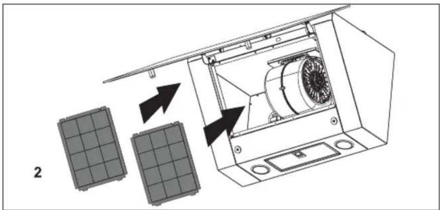
text_image
2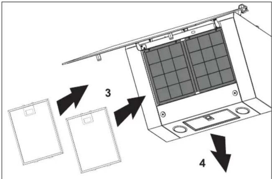
text_image
Diagram showing a device with labeled components and directional arrows indicating assembly or movement.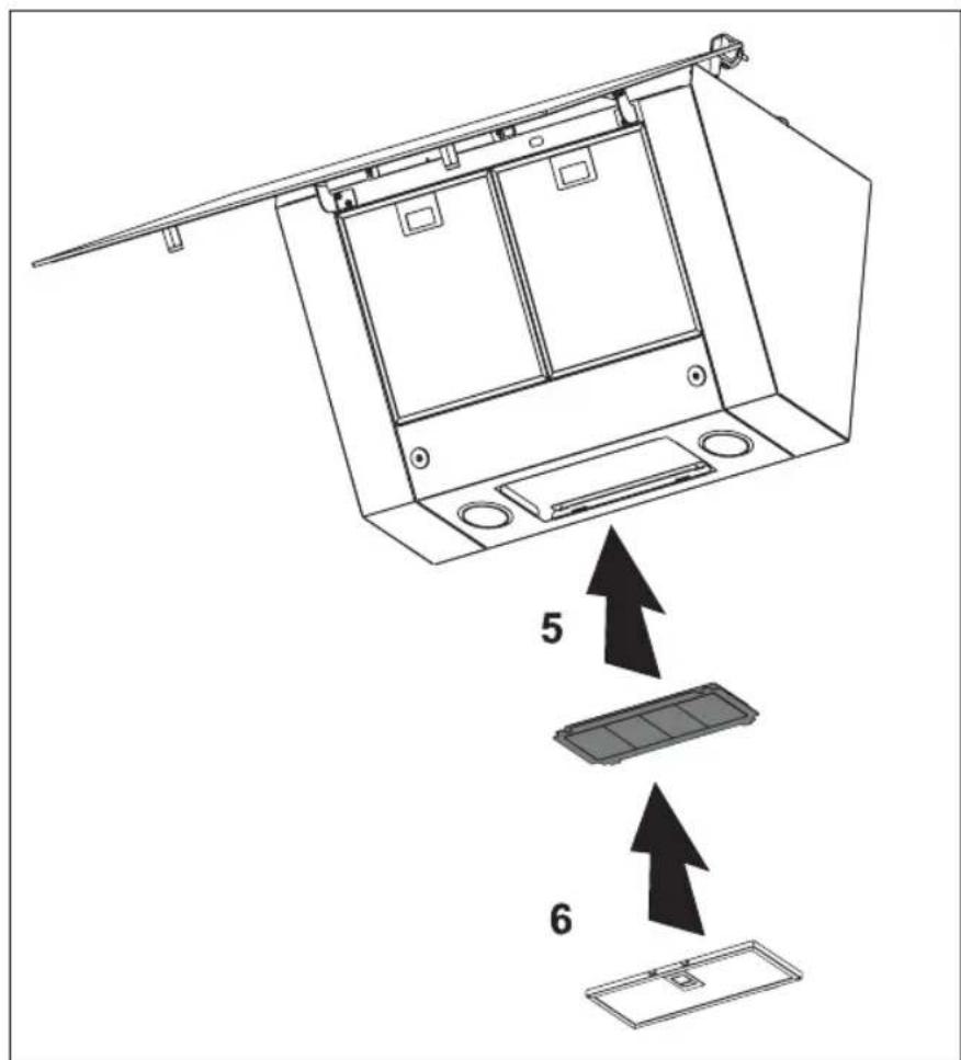
text_image
Diagram showing a device interior with labeled components and directional arrows indicating assembly or installation steps.text_image
Diagram showing a device with labeled components and signal paths, including a sensor or sensor device and directional arrows.Montage
text_image
400 246 164 400 175 101 61,5 370 1 3 4 + + + + + + + + + + + + + + + + + + + + + + + + + + + + + + + + + + + + + + + - 7 7 7 6 5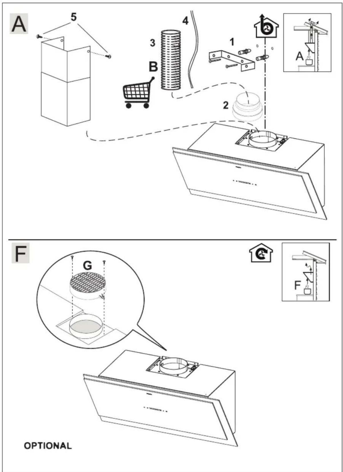
text_image
A 5 3 4 B 1 2 A F G OPTIONALAfvoeren
natural_image
Symbol of a trash bin with crossed lines indicating no waste or discharge, plus a black rectangular base (no text or numbers present)natural_image
Diagram of a brick wall with a ladder and a cabinet, showing airflow direction (no text or symbols)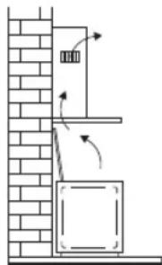
natural_image
Diagram of a cabinet or elevator system with directional arrows indicating flow or movement, mounted on a brick wall (no text or symbols present)
natural_image
Technical diagram of an air conditioner unit with internal fan and mounting holes, showing directional arrows (no text or symbols)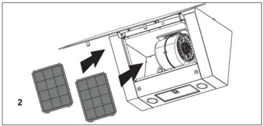
text_image
2
text_image
Diagram showing a device with labeled components and directional arrows indicating assembly or movement.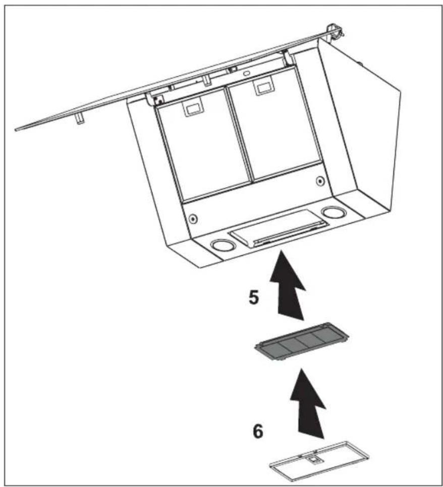
text_image
Diagram showing a device interior with labeled components and directional arrows indicating assembly or installation steps.$$ \text { MARRON } = \text { Phase (L) } $$
$$ \mathrm{BLEU} = \text { N e u t r e } (\mathrm{N}) $$
$$ \text { V E R T / J A U N E } = \text { T e r r e } $$
text_image
Diagram showing a device with labeled components and directional arrows, likely illustrating a system or control system.Montage
text_image
400 246 164 400 175 101 61,5 370 1 3 4 + + + + + + + + + + + + + + + + + + + + + + + + + + + + - 7 7 7 6 5
text_image
A 5 3 4 B 1 2 A F G OPTIONALFR 14 Pelgrim
Mise au rebut
natural_image
Symbol of a trash bin with crossed lines indicating no waste or discharge (no text or numbers present)natural_image
Diagram of a brick wall with a ladder and a cabinet, showing airflow direction (no text or symbols)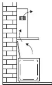
natural_image
Diagram of a cabinet with directional arrows indicating movement, mounted on a brick wall (no text or symbols)
natural_image
Diagram of a refrigerator interior showing fan and door mechanism with arrows indicating motion (no text or symbols)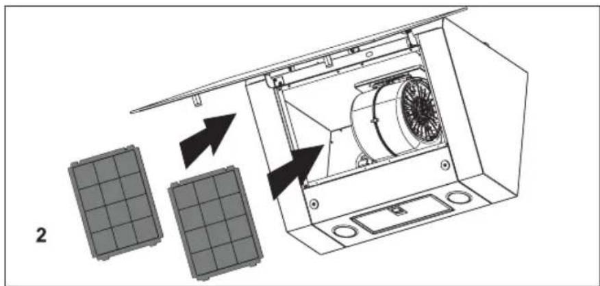
text_image
2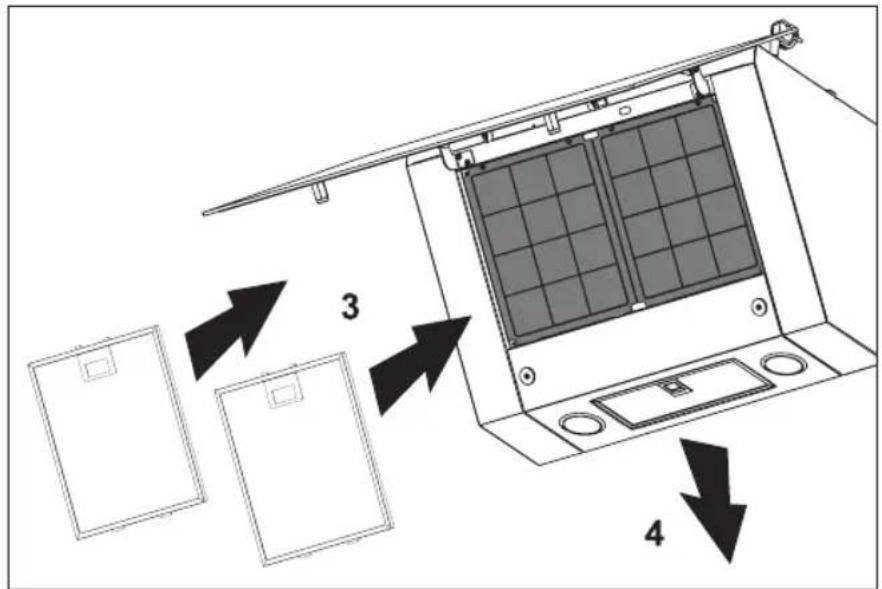
text_image
Diagram showing a device with labeled components and directional arrows indicating assembly or movement steps.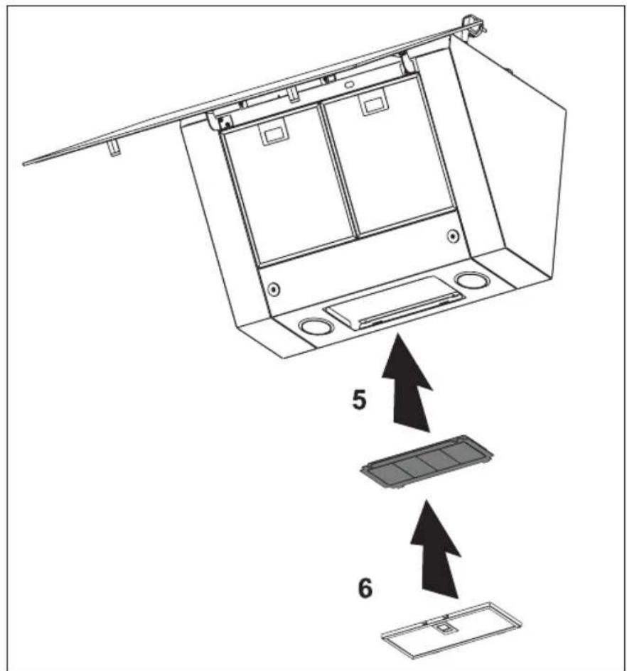
text_image
Diagram showing a device interior with labeled components and directional arrows indicating assembly or installation steps.text_image
Diagram showing a device with labeled components and directional arrows, likely illustrating a system or control setup.Montage
text_image
400 246 164 400 175 101 61,5 370 1 3 4 + + + + + + + + + + + + + + + + + + + + + + + + + + + - 7 7 7 6 5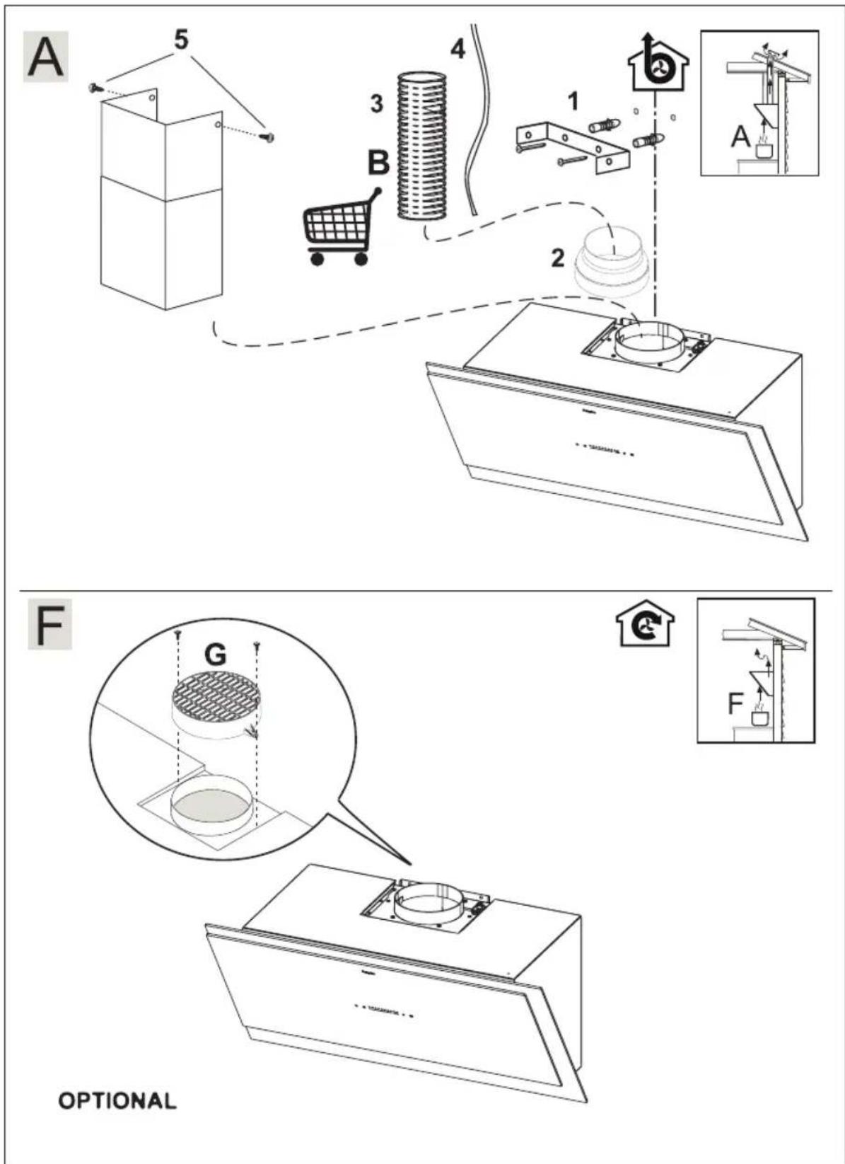
text_image
A 5 3 4 B 1 2 A F G OPTIONALEntsorgung
natural_image
Symbol of a trash bin with crossed lines indicating no waste or discharge, and a black rectangle below (no text or labels)Cleaning the filters 6
Maintenance
Cleaning 7
Grease filters 8
Carbon filters 8
Light 10
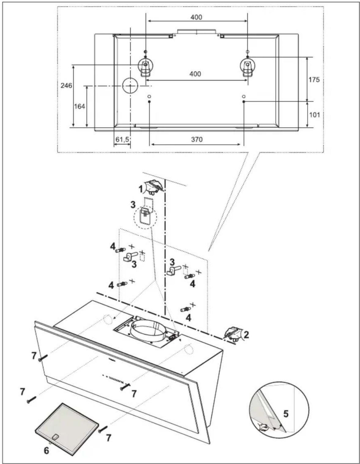
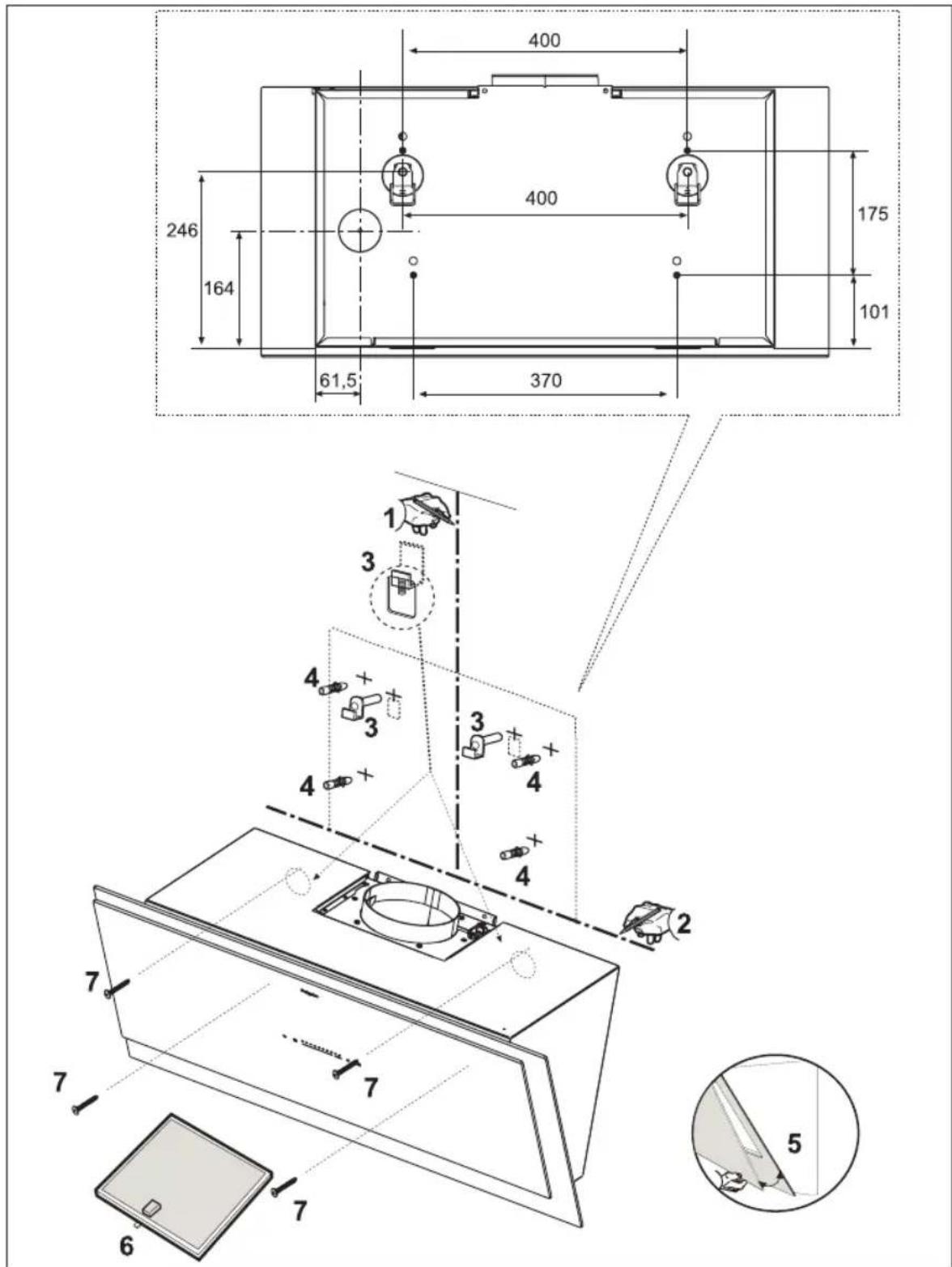
Installation
General 11
Connection 12
Assembly 13
Annex
Disposal 15
Introduction
Read through this user manual for quick information about all the options available to you with this appliance. It gives safety information and instructions for maintaining the appliance.
Keep the user manual and the installation instructions. They will be useful to any subsequent user of this appliance.
Read the separate safety instructions before using the appliance.
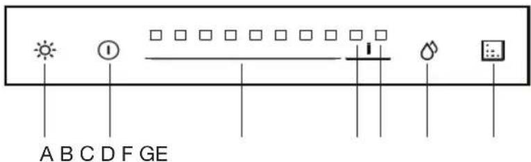
Description
text_image
A B C D F GEA Light On/Off key
B On/Off key
C Speed keys (speed 1 to 8)
D Intensive speed key 1
E Intensive speed key 2
F Grease filter saturation indicator/key
G Carbon filter saturation indicator/key
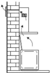
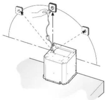
Exhaust systems
The cooker hood can, depending on the model, be connected in one of two ways:
- As a cooker hood connected to an exhaust duct. The cooking fumes are drawn into the cooking hood, filtered, and exhausted outdoors. This is the best way!
- As a recirculation cooker hood. The cooking fumes are drawn into the cooking hood and the grease droplets and odours are filtered out. The filtered air is not exhausted outdoors, but is returned to the kitchen. You then need to fit carbon filters.
natural_image
Diagram of a brick wall with a ladder and a cabinet, showing directional arrows indicating movement (no text or symbols)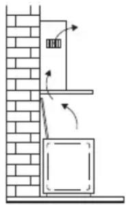
natural_image
Diagram of a vertical structure with brick wall and hanging box, showing airflow direction (no text or symbols)
Note! Carbon filters must be ordered separately.
Operation
Switching the fan On and Off
- Switch the fan on by touching the On/Off key.
- Select the required extractor speed by touching the speed keys or one of the Intensive speed keys.
- Intensive speed 1 will automatically switch to setting 8 after 8 minutes.
- Intensive speed 2 will automatically switch to setting 8 after 7 minutes.
- Switch the fan Off by touching the On/Off key.
Switching the lighting on and off
- Touch the light key.
The light turns On. - Touch the light key again.
The light turns Off.

Cleaning the filters
After 4 hours of not operating the cooker hood will switch itself Off automatically.
Saturated grease filters
When starting extraction the grease filter saturation indicator light up for 5 seconds in a colour that indicates the level of filter saturation:
• Green: 0-75% saturation
• Oranje: 76-99% saturation
• Red: Grease filter has to be cleaned
Saturated carbon filters
When starting extraction the carbon filter saturation indicator light up for 5 seconds in a colour that indicates the level of filter saturation:
• Green: 0-75% saturation
• Oranje: 76-99% saturation
- Red: Carbon filter has to be cleaned or replaced
After cleaning or replacing the filter touch the saturation indicator keys to reset the memory.

Do not reset the memory until the maintenance work on the filters has been completed.
Cleaning
Attention! Before carrying out maintenance work, always disconnect the cooker hood from the power supply by pulling out the plug or switching off the power at the fuse box. The hood must be cleaned regularly, both inside as well as outside (with at least the same regularity as used for cleaning the grease filters). Do not use any products that contain abrasive materials. Do not clean with alcohol!
Attention! If you do not follow these instructions with regards to the cleaning of the appliance and the cleaning or replacement of the filters, this can lead to fire. It is essential to follow these instructions!
The manufacturer is not liable for damage to the motor or damage as a result of fire that is due to improper servicing or not following the above safety requirements.
Cooker hood
Clean the cooker hood with soapy water and a soft cloth. Then treat with clean water. Do not use any aggressive cleaning agents such as soda. The lacquer of the cooker hood will remain in good condition if you rub the lacquer with wax once in a while.
Stainless steel hoods
Do not use scouring sponges or other abrasives on stainless steel hoods. Finish with a non-abrasive, non-polishing agent and scrub in the direction of the brushing of the stainless steel.
Metal grease filters
Metal filters need to be cleaned once per month (or when indicated by the filter cleaning indicator if present on the model) with neutral cleaning agents, by hand or in the dishwasher at low temperatures using a short programme. Place the grease filters in the dishwasher with the openings facing down so that water can run out. Aluminium grease filters will become dull from the cleaning agents in the dishwasher. This is normal and does not affect the functioning of the filters.
MAINTENANCE
Grease filters
Carbon filters
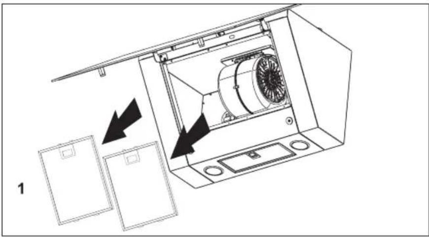
Removing the grease filters
- Remove the filters one by one by pulling on their release handles.
Replacing the carbon filters
Use carbon filters when the cooker hood is not connected to an exhaust duct.
Important:
The odor filter is clamped on top of the grease filter. Prevent the odor filter from falling on your hob by supporting it when installing and removing the filters.
- Remove the grease filters.
- Fit the carbon filters in the cooker hood.
- Fit the grease filters.
natural_image
Technical line drawing of an open air conditioner unit with internal fan and ventilation system (no text or symbols)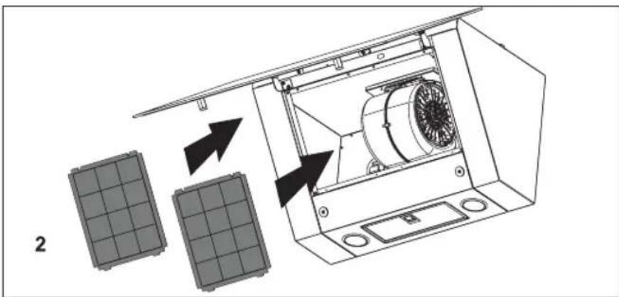
text_image
2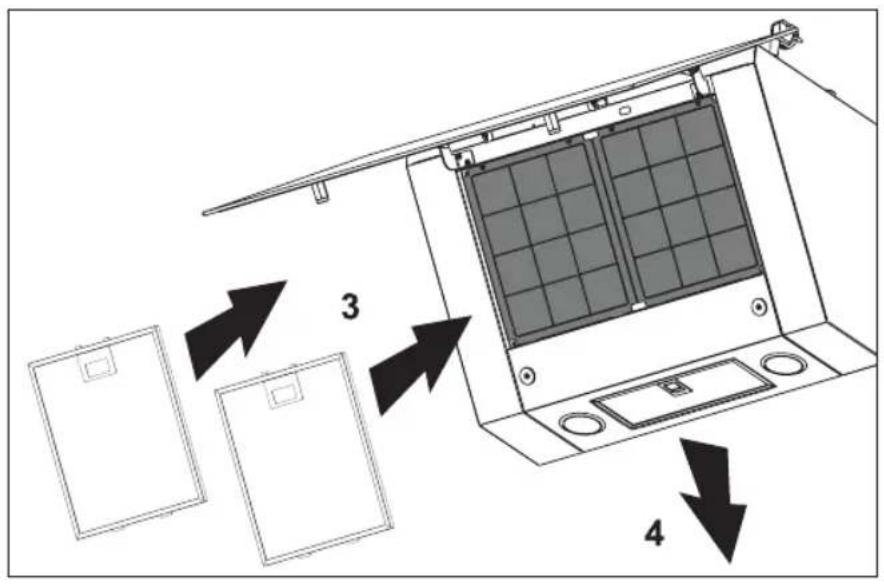
text_image
Diagram showing a device with three labeled components and directional arrows indicating assembly or movement.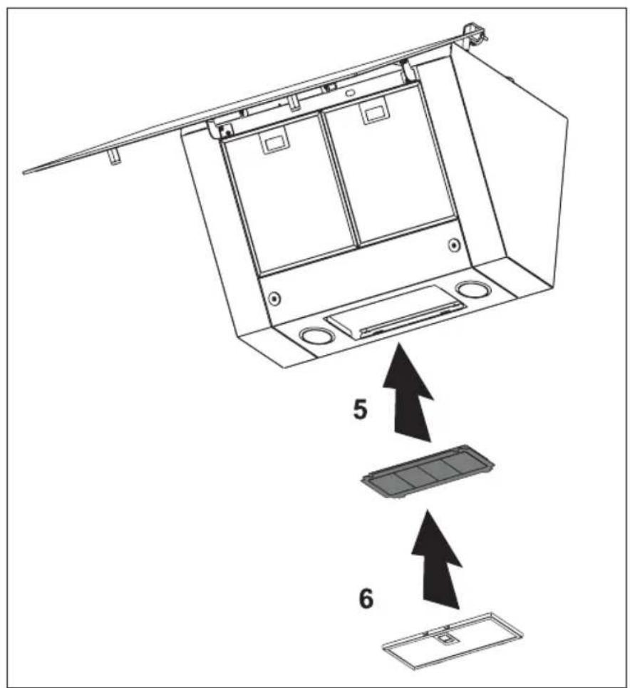
text_image
5 6MAINTENANCE
The regenerable active carbon filters can be washed by hand or in the dishwasher at a maximum temperature of 65^ C. The washing cycle must be done without other dishes and without dishwasher detergent. Do not use any cleaning agents!
Remove excess water. Be careful to avoid damaging the filter. Place the filter in the oven to dry for at least 1 hour at a maximum temperature of 80^ . After up to 3 years (or if the filtres are damaged), the filters will need to be replaced. It is important that the grease filters and the regenerable active carbon filters are properly dried before installation.
The functioning:
- More noise is produced when carbon filters are used than when the cooker hood is used with an exhaust vent.
- Carbon filters function optimally at a lower motor speed. For this reason, avoid the boost function.
Lighting
• The cooker hood is fitted with LED lighting.
- LED lamps guarantee you optimum lighting, a service life of up to 10 times longer than conventional lamps and energy savings of as much as 90%.
Contact the technical department when LED lighting needs to be replaced.
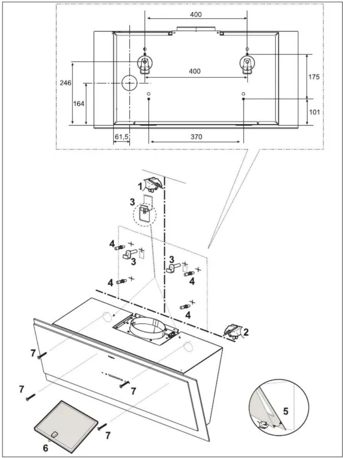
General
This appliance must be connected to the power supply by a recognized installer who is familiar with and works in accordance with the applicable safety regulations. This appliance conforms to the European directives.
Important information:
- The lowest part of the cooker hood must be at least 65 cm above a gas hob. The lowest part of the cooker hood must be at least 55 cm above an electric, ceramic or induction hob.
- The cooker hood may only be connected to an existing exhaust duct to which no other appliances are connected (such as a geyser or heater).
- Gas appliances must be vented in accordance with the local regulations.
- The cooker hood works best when connected to an exhaust duct that is as short and as straight as possible.
- Before drilling any holes, always check to make sure that there are no wires in the area.
- The hood's connection pipe has a diameter of 120 or 150mm . The exhaust duct should preferably be of the same diameter.
- The installation materials supplied with this cooker hood are suitable for reinforced concrete and masonry walls. You will need special plugs and screws to fasten the appliance to some other types of wall.
Connection
Electrical connections
This appliance is a Class I appliance and must be earthed.
Check to make sure that the voltage specified on the type plate matches the mains voltage. The appliance must be connected to the mains as follows:
$$ B R O W N = L (\text { live }) $$
$$ B L U E = N (\text { neutral }) $$
$$ \text { GREEN / YELLOW } = \text { Earth } $$
This cooker hood is fitted with a plug. Install the cooker hood so that the plug is accessible. It is preferable to fit the wall socket out of sight, behind the chimney cover.
Note: When you make a fixed connection to the mains you must make sure that the live wire is connected to an omnipolar switch with a break contact distance of at least 3 mm.
Max. 125 cm
text_image
Diagram illustrating a mechanical or electrical setup with labeled components and directional arrows, likely for system or control analysis.Assembly
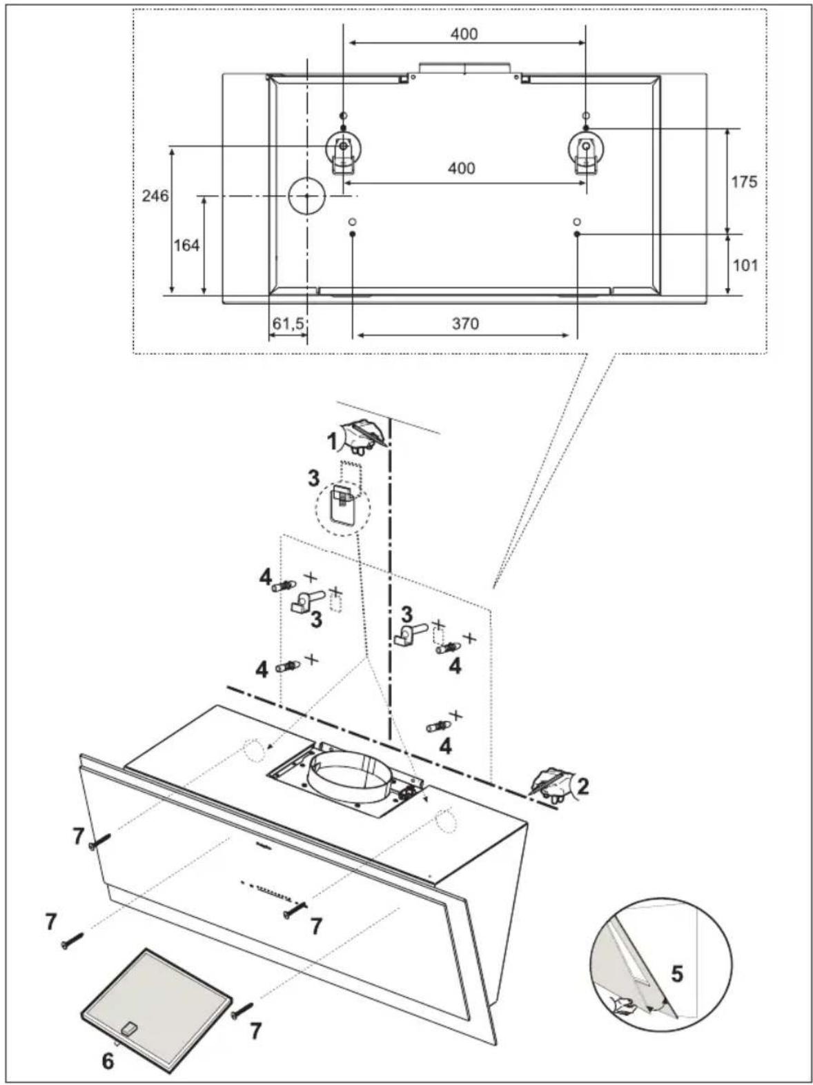
text_image
400 246 164 400 175 101 61,5 370 1 3 4 + + + + + + + + + + + + + + + + + + + + + + + + + + + - 7 7 7 6 5 2
text_image
A 5 3 4 B 1 2 A F G OPTIONALDisposal
Disposal of packaging and appliance
Sustainable materials were used in the manufacture of this appliance. At the end of its life cycle, this appliance must be disposed of in a responsible manner. You can obtain more information from the authorities.
The packaging of the appliance is recyclable. The following materials may have been used:
- cardboard;
• polyethylene foil (PE);
• CFC-free polystyrene (PS hard foam).
Dispose of these materials in a responsible manner and in accordance with governmental provisions.
natural_image
Symbol of a trash bin with crossed lines indicating no waste or discharge, plus a black rectangular block below (no text or labels)To designate the requirement of sorted processing of electrical household equipment, the symbol of a crossed-out waste container is displayed on the product. This means that at the end of its life span, the appliance may not be added to the regular household waste. The appliance must be brought to a special municipal centre for sorted waste collection or to a dealer that provides this service.
The separate processing of a household appliance prevents possible negative consequences for the environment and health which exist due to inappropriate processing. Separate processing ensures that the materials of which the appliance is made can be recovered to obtain a considerable savings of energy and raw materials.
CE
Conformity declaration
We declare that our products comply with the applicable European Directives, Resolutions and Regulations, as well as all requirements specified in the standards to which reference is made.
text_image
Warning symbol with exclamation mark inside a trianglePelgrim
text_image
Barcode image with black and white vertical bars, no visible text or symbols beyond the pattern808665