
RM-TP503 - Remote control SONY - Free user manual and instructions
Find the device manual for free RM-TP503 SONY in PDF.
| Product Type | Universal touchscreen remote control |
| Brand | Sony |
| Model | RM-TP503 |
| Dimensions (W x H x D) | 160 x 111 x 46 mm |
| Weight | 290 g (with stylus) |
| Power | 4 AA alkaline batteries (6 V) + 1 CR2032 lithium battery (memory backup) |
| Screen Type | 3.8-inch monochrome LCD (256 x 200 pixels), backlit |
| Control Technology | Bidirectional infrared |
| Main Functions | Control of amplifier/tuner and audio/video devices, source selection, sound field adjustment, equalizer, macro commands, code learning, CD/MD title display |
| Compatible Devices | Sony and other brand devices (with initial setup) |
| Connectivity | IR transmitter/receiver section, receiver for learning |
| Care and Cleaning | Clean with a soft cloth lightly dampened with a mild detergent solution. Do not use solvents. |
| Safety | Do not bend the touch panel (glass). Use only the included stylus or your fingertip. |
| Battery Life | Approximately 2.5 months (60 operations/day, backlight on) |
Frequently Asked Questions - RM-TP503 SONY
User questions about RM-TP503 SONY
0 question about this device. Answer the ones you know or ask your own.
Ask a new question about this device
Download the instructions for your Remote control in PDF format for free! Find your manual RM-TP503 - SONY and take your electronic device back in hand. On this page are published all the documents necessary for the use of your device. RM-TP503 by SONY.
USER MANUAL RM-TP503 SONY
Operating Instructions GB
Mode d'emploi FR
CAUTION (Lithium battery)
Danger of explosion if battery is incorrectly replaced. Replace only with the same or equivalent type recommended by the manufacturer. Discard used batteries according to the manufacturer's instructions.
On operation
Before connecting other components, be sure to turn off and unplug the receiver/amplifier.
On cleaning
Clean the cabinet, panel and controls with a soft cloth slightly moistened with a mild detergent solution. Do not use any type of abrasive pad, scouring powder or solvent such as alcohol or benzine.
If you have any question or problem concerning your commander, please consult your nearest Sony dealer.
About This Manual
- The following icon is used in this manual:
Indicates hints and tips for making the task easier.
Before You Use the Commander
Understanding the 2 way remote system
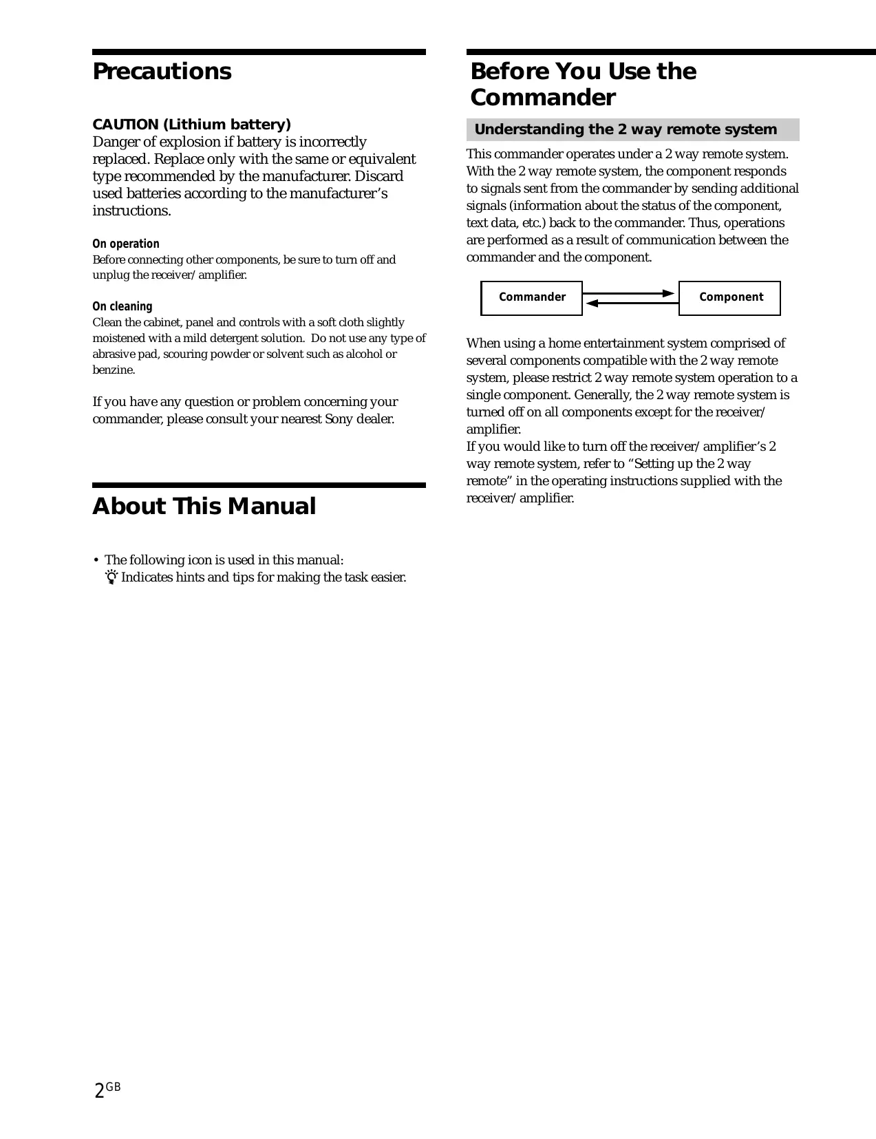
This commander operates under a 2 way remote system. With the 2 way remote system, the component responds to signals sent from the commander by sending additional signals (information about the status of the component, text data, etc.) back to the commander. Thus, operations are performed as a result of communication between the commander and the component.
flowchart
graph LR
    A["Commander"] <--> B["Component"]
When using a home entertainment system comprised of several components compatible with the 2 way remote system, please restrict 2 way remote system operation to a single component. Generally, the 2 way remote system is turned off on all components except for the receiver/amplifier.
If you would like to turn off the receiver/amplifier's 2 way remote system, refer to “Setting up the 2 way remote” in the operating instructions supplied with the receiver/amplifier.
Special Remarks
■ About the LCD
Depending on the brightness of the room and the angle at which the commander is viewed, the LCD may be difficult to see. When this occurs, changing the angle of the commander or adjusting the CONTRAST of the LCD may make the LCD easier to see. When fingerprints (etc.) get on the LCD, wipe the LCD with a soft, dry cloth. It is recommended to use the touch pen supplied with the commander.
■ About batteries
Life span of the batteries
This commander is different from conventional remotes in that it makes use of a large LCD and is capable of 2 way communication. Because of this, the batteries become exhausted more quickly than with conventional remotes.
Under normal conditions, the batteries should last approximately 2.5 months*. However, depending on how the remote is used and the initial voltage of the batteries, the actual period of use may be shorter or longer than that mentioned above.
* This value is based on 60 key operations a day with the backlight on. If the backlight is turned off, the batteries should last much longer. In order to extend the life of the batteries, it is recommended to keep the backlight off when operating the commander in a well lit area.
TABLE OF CONTENTS
Preparations 4
Compatible Components and Functions 4
Preparing the Commander 5
Screen Hierarchy 8
Location of Parts and Basic Operations 9
Front panel 9
Rear panel 10
Operation 11
Basic Operations 11
Example: Operating a CD Player 13
Example: Operating the Tuner 14
Example: Recording from CD to MD 15
Performing Several Commands in Sequence Automatically (Macro Play) 16
Using a command that has been learned 17
Selecting a source to listen to using SUB ROOM 17
Selecting Sound Fields 18
Adjusting Sound Fields 21
Adjusting the Commander's Operating Environment 24
Additional information 31
Precautions during use 31
Troubleshooting 32
Specifications 33
Index 33
Preparations
This chapter describes how to prepare the remote commander for operation. Be sure to read this section before operating.
Compatible Components and Functions
This unit is a remote control system that utilizes infrared rays to control a receiver/amplifier and AV components connected to the receiver/amplifier.
Compatible Components
This unit can be used to operate Sony AV components as well as AV components made by other manufacturers. Setup is necessary in order to operate components made by other manufacturers (see page 24).
Note
Depending on the component, control may not be possible using this unit.
Functions
This unit is a 2 way remote commander. Not only does it transmit infrared rays for operation of the receiver/amplifier, it also receives infrared rays emitted by the receiver/amplifier to display characters and other information from components connected to the receiver/amplifier with a CONTROL A1 cord.
Preparing the Commander
Please be sure to carry out the procedures described in "Setting up the commander" on page 6 after inserting the batteries.
Inserting batteries into the commander
Insert the four size-AA (LR6) alkaline batteries (for commander operation) and the lithium battery (for preservation of the commander's internal memory).
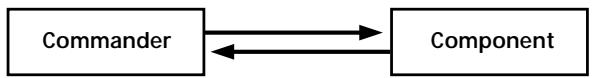
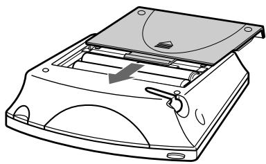
1 Remove the battery compartment cover.
2 Insert the alkaline batteries.

Always insert the negative (−) pole side of batteries first.
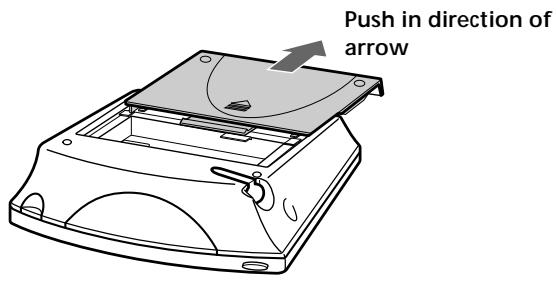
3 Insert the lithium battery.
After wiping the lithium battery thoroughly with a dry cloth, insert it into the compartment with the positive (+) pole side facing up.
Positive (+) pole side up
4 Close the battery compartment cover.
natural_image
Line drawing of a mechanical device with a curved top component and internal components (no text or symbols)After inserting the batteries, touching the touch panel turns on the light and displays the touch panel (LCD) adjustment screen. Follow the procedure on the next page for touch panel adjustment and initial communication.

Notes
- The LCD lights up when touched.
- VOL +/-, MUTING and SLEEP can be used even when the LCD is not lit.
- Pressing BACK LIGHT/COMMANDER OFF turns the backlight on or off. Holding it down for about 2 seconds turns the LCD off.
- If the commander is not used for 10 seconds, the LCD turns off automatically (Auto Off function).
Setting up the commander
Please be sure to carry out the following 5 steps for preparation of the commander. The commander's panel is touch sensitive and can be operated by simply touching it.
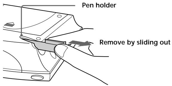
1 Remove the touch pen.
When returning the touch pen, always slide it in tip first.
Caution
Use only the touch pen provided with this unit or the soft tip of your finger to operate the touch panel. Using a commercially available writing utensil may damage the panel and make correct operation impossible. If the tip of the touch pen is damaged, or the touch pen is lost, please consult your nearest Sony dealer.
2 Turn CONTRAST to adjust brightness of the LCD.
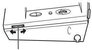
CONTRAST control
Touch panel adjustment
3 Adjust the position of the touch panel's LCD. Touch the center of each of the 4 dots with the touch pen. When all 4 dots have been touched "Adjusted" appears, a buzzer sounds, and the initial communication screen appears.
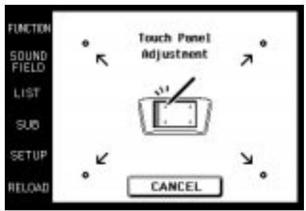

Touch the 4 dots with the touch pen.
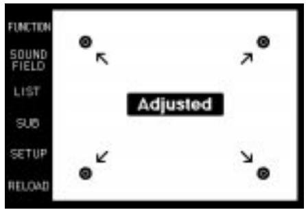
Caution
Touch panel adjustment must be carried out for proper panel operation. If used without adjustment, the "Touch Panel Adjustment" screen appears each time the LCD lights up.
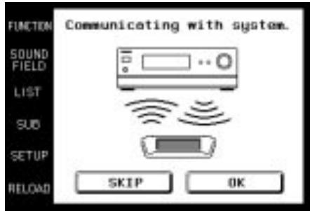
Initial communication
4 Press I/⏻ on the receiver/amplifier to turn on the receiver/amplifier.
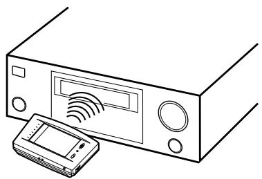
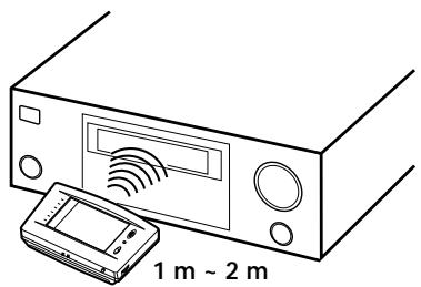
5 Point the commander's transmitter/receiver section toward the receiver/amplifier's display, and touch OK.
Once initial communication with the receiver/amplifier has been established, the commander is ready to operate the receiver/amplifier.

natural_image
Line drawing of a portable electronic device with a sensor array and a handheld device, labeled '1 m ~ 2 m' (no text or symbols on the device itself)Notes
- To ensure good communication conditions, carry out initial setup from directly in front of, and close to the receiver/amplifier.
- Do not move the unit during initial setup.
If a communication error occurs during setup
An error message will be displayed.
- Touching OK will return to the step 5 setup screen.
- Touching SKIP goes to the regular screen without carrying out initial setup. Although operation is possible in this condition, functions not included on the receiver/amplifier will be displayed, and some buttons will not be operable. Also, the initial setup screen will appear each time the touch panel is turned on.
Note
The commander receives and displays data transmitted from the receiver/amplifier. Communication errors may occur if the commander's transmitter/receiver section is not directed properly toward the receiver/amplifier's display. Be sure to point the commander's transmitter/receiver section towards the receiver/amplifier's display.
When replacing the batteries
To ensure preservation of the commander's internal memory when replacing batteries, be sure to observe the following cautions.
When to replace batteries
When the batteries become weak, a warning sounds and a message is displayed. Replace batteries as instructed by the message.
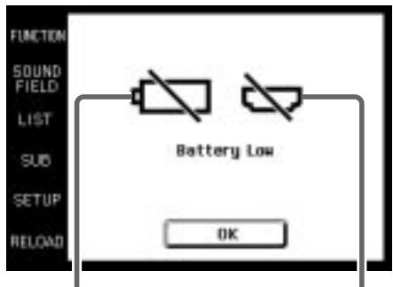
Replace alkaline batteries.
Replace lithium battery.
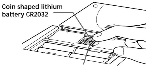
How to remove the lithium battery
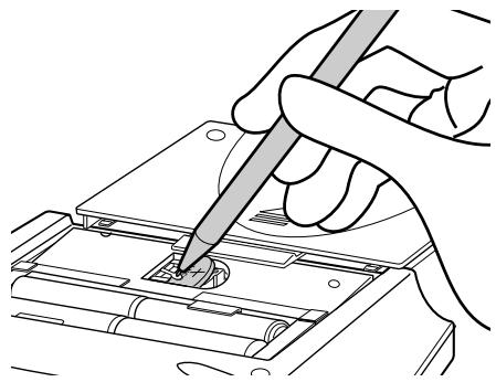
natural_image
Illustration of hands using a tool to adjust or install electronic components (no text or symbols visible)Notes
- Disc titles and song titles downloaded from the CD changer are memorized in the commander. The lithium battery is used for preservation of this memory. If the unit is used with an exhausted battery, the settings memorized in the commander will be erased. Please replace the battery as soon as the “Battery Low” message appears.
- Replace the alkaline batteries with new batteries as soon as their charge is exhausted. If the unit is used with exhausted batteries, exhaustion of the lithium battery used to maintain memory will be quickened and the memorized settings may be erased.
- The life span of batteries may be shortened depending on the conditions in which the commander is used.
- If the alkaline batteries and lithium battery become exhausted at the same time, replace the alkaline batteries first. Replacing the lithium battery first will erase the data memorized in the commander.
- When replacing the alkaline batteries, always replace all 4 batteries with new ones.
- After replacing batteries, be sure to carry out touch panel adjustment (page 6).
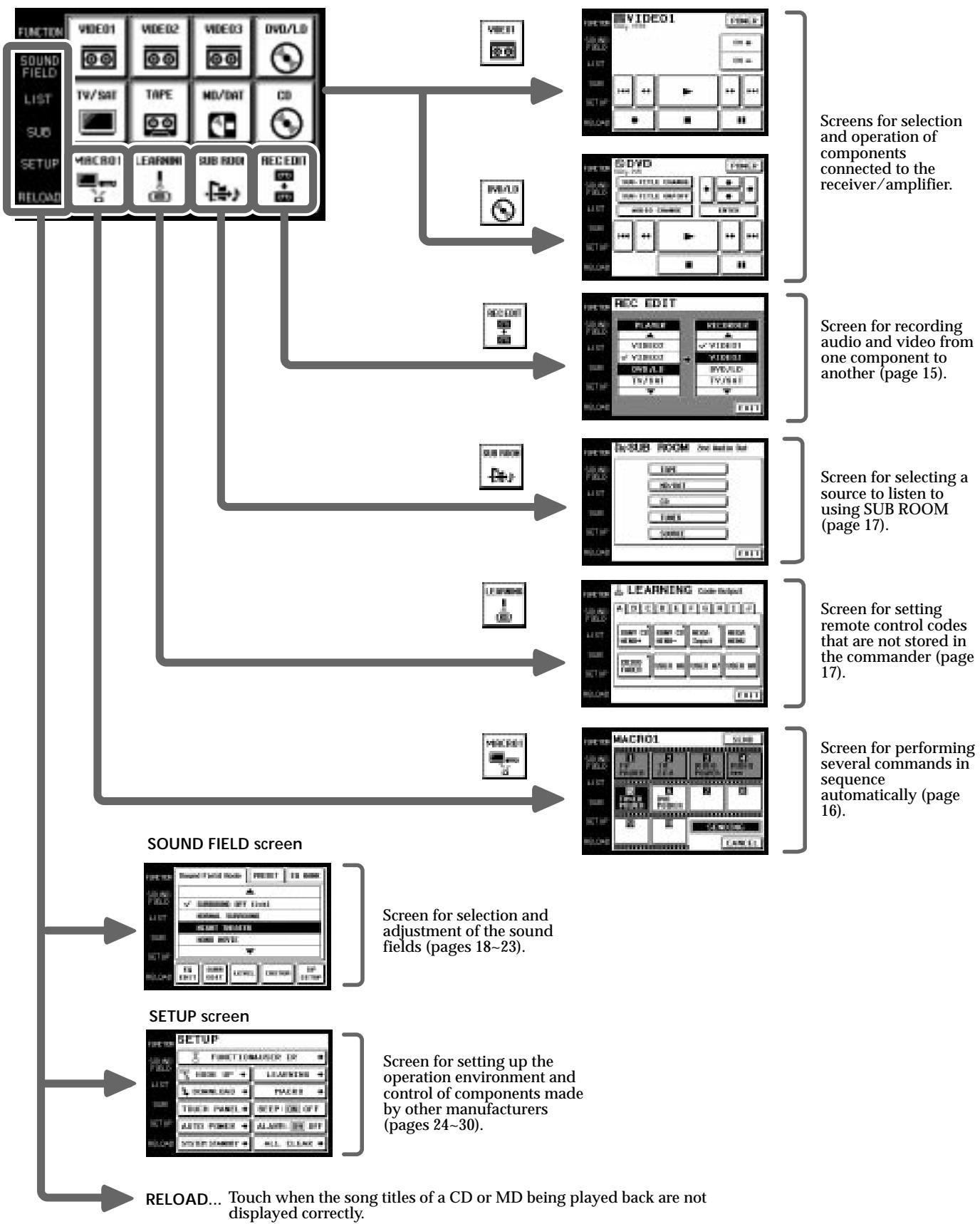
Screen Hierarchy
The following diagram shows the basic composition of this unit's screen hierarchy.
FUNCTION screen Normally, the FUNCTION screen is displayed. To display a different screen, touch the left side of the LCD.
flowchart
graph TD
    A["FUNCTION"] --> B["SOUND FIELD screen"]
    B --> C["SETUP screen"]
    C --> D["RELOAD... Touch when the song titles of a CD or MD being played back are not displayed correctly."]

    subgraph SOUND_FIELD spectrum
        B --> E["SOUND FIELD screen"]
        E --> F["SETUP screen"]
    end

    subgraph SOUND_FIELD spectrum
        B --> G["SOUND FIELD screen"]
        G --> H["SETUP screen"]
    end

    subgraph SETUP spectrum
        C --> I["SOUND FIELD screen"]
        I --> J["SETUP screen"]
    end

    B --> K["REFLOOD"]
    B --> L["MACRO1"]
    B --> M["LEARNINI"]
    B --> N["SUB ROOM"]
    B --> O["REC EDIT"]

    subgraph OUTPUT spectrum
        K --> P["REFLOOD"]
        K --> Q["SOUND FIELD screen"]
        Q --> R["SETUP screen"]
    end

    subgraph OUTPUT spectrum
        R --> S["SOUND FIELD screen"]
        S --> T["SETUP screen"]
    end

    subgraph OUTPUT spectrum
        T --> U["REFLOOD"]
        T --> V["SOUND FIELD screen"]
        V --> W["SETUP screen"]
    end

    subgraph OUTPUT spectrum
        W --> X["SOUND FIELD screen"]
        X --> Y["SETUP screen"]
    end

    subgraph OUTPUT spectrum
        Y --> Z["SOUND FIELD screen"]
        Z --> AA["SETUP screen"]
    end

    subgraph OUTPUT spectrum
        AA --> AB["SOUND FIELD screen"]
        AB --> AC["SETUP screen"]
    end

    subgraph OUTPUT spectrum
        AC --> AD["SOUND FIELD screen"]
        AD --> AE["SETUP screen"]
    end

    subgraph OUTPUT spectrum
        AE --> AF["SOUND FIELD screen"]
        AF --> AG["SETUP screen"]
    end

    subgraph OUTPUT spectrum
        AG --> AH["SOUND FIELD screen"]
        AH --> AI["SETUP screen"]
    end

    subgraph OUTPUT spectrum
        AI --> AJ["SOUND FIELD screen"]
        AJ --> AK["SETUP screen"]
    end

    subgraph OUTPUT spectrum
        AK --> AL["SOUND FIELD screen"]
        AL --> AM["SETUP screen"]
    end

    subgraph OUTPUT spectrum
        AM --> AN["SOUND FIELD screen"]
        AN --> AO["SOUND FIELD screen"]
    end

    subgraph OUTPUT spectrum
        AO --> AP["SOUND FIELD screen"]
        AP --> AQ["SOUND FIELD screen"]
    end

    subgraph OUTPUT spectrum
        AQ --> AR["SOUND FIELD screen"]
        AR --> AS["SOUND FIELD screen"]
    end

    subgraph OUTPUT spectrum
        AS --> AT["SOUND FIELD screen"]
        AT --> AU["SOUND FIELD screen"]
    end

    subgraph OUTPUT spectrum
        AU --> AV["SOUND FIELD screen"]
        AV --> AW["SOUND FIELD screen"]
    end

    subgraph OUTPUT spectrum
        AW --> AX["SOUND FIELD screen"]
        AX --> AY["SOUND FIELD screen"]
    end

    subgraph OUTPUT spectrum
        AY --> AZ["SOUND FIELD screen"]
        AZ --> BA["SOUND FIELD screen"]
    end

    subgraph OUTPUT spectrum
        BA --> BB["SOUND FIELD screen"]
        BB --> BC["SOUND FIELD screen"]
    end

    subgraph OUTPUT spectrum
        BC --> BD["SOUND FIELD screen"]
        BD --> BE["SOUND FIELD screen"]
    end

    subgraph OUTPUT spectrum
        BE --> BF["SOUND FIELD screen"]
        BF --> BG["SOUND FIELD screen"]
    end

    subgraph OUTPUT spectrum
        BG --> BH["SOUND FIELD screen"]
        BH --> BI["SOUND FIELD screen"]
    end

    subgraph OUTPUT spectrum
        BI --> BJ["SOUND FIELD screen"]
        BJ --> BK["SOUND FIELD screen"]
    end

    subgraph OUTPUT spectrum
        BK --> BL["SOUND FIELD screen"]
        BL --> BM["SOUND FIELD screen"]
    end

    subgraph OUTPUT spectrum
        BM --> BN["SOUND FIELD screen"]
        BN --> BO["SOUND FIELD screen"]
    end

    subgraph OUTPUT spectrum
        BO --> BP["SOUND FIELD screen"]
        BP --> BQ["SOUND FIELD screen"]
    end

    subgraph OUTPUT spectrum
        BQ --> BR["SOUND FIELD screen"]
        BR --> BS["SOUND FIELD screen"]
    end

    subgraph OUTPUT spectrum
        BS --> BT["SOUND FIELD screen"]
        BT --> BU["SOUND FIELD screen"]
    end

    subgraph OUTPUT spectrum
        BU --> BV["SOUND FIELD screen"]
        BV --> BW["SOUND FIELD screen"]
    end

    subgraph OUTPUT spectrum
        BW --> BX["SOUND FIELD screen"]
        BX --> BY["SOUND FIELD screen"]
    end

    subgraph OUTPUT spectrum
        BY --> BZ["SOUND FIELD screen"]
        BZ --> CA["SOUND FIELD screen"]
    end

    subgraph OUTPUT spectrum
        CA --> CB["SOUND FIELD screen"]
        CB --> CC["SOUND FIELD screen"]
    end

    subgraph OUTPUT spectrum
        CC --> CD["SOUND FIELD screen"]
        CD --> CE["SOUND FIELD screen"]
    end

    subgraph OUTPUT spectrum
        CE --> CF["SOUND FIELD screen"]
        CF --> CG["SOUND FIELD screen"]
    end

    subgraph OUTPUT spectrum
        CG --> CH["SOUND FIELD screen"]
        CH --> CI["SOUND FIELD screen"]
    end

    subgraph OUTPUT spectrum
        CI --> CJ["SOUND FIELD screen"]
        CJ --> CK["SOUND FIELD screen"]
    end

    subgraph OUTPUT spectrum
        CK --> CL["SOUND FIELD screen"]
        CL --> CM["SOUND FIELD screen"]
    end

    subgraph OUTPUT spectrum
        CM --> CN["SOUND FIELD screen"]
        CN --> CO["SOUND FIELD screen"]
    end

    subgraph OUTPUT spectrum
        CO --> CP["SOUND FIELD screen"]
        CP --> CQ["SOUND FIELD screen"]
    end

    subgraph OUTPUT spectrum
        CQ --> CR["SOUND FIELD screen"]
        CR --> CS["SOUND FIELD screen"]
    end

    subgraph OUTPUT spectrum
        CS --> CT["SOUND FIELD screen"]
        CT --> CU["SOUND FIELD screen"]
    end

    subgraph OUTPUT spectrum
        CU --> CV["SOUND FIELD screen"]
        CV --> CW["SOUND FIELD screen"]
    end

    subgraph OUTPUT spectrum
        CW --> CX["SOUND FIELD screen"]
        CX --> CY["SOUND FIELD screen"]
    end

    subgraph OUTPUT spectrum
        CX --> CZ["SOUND FIELD screen"]
        CZ --> DA["SOUND FIELD screen"]
    end

    subgraph OUTPUT spectrum
        DQ --> DB["SOUND FIELD screen"]
        DB --> DC["SOUND FIELD screen"]
    end

    subgraph OUTPUT spectrum
        DC --> DE["SOUND FIELD screen"]
        DE --> DF["SOUND FIELD screen"]
    end

    subgraph OUTPUT spectrum
        DF --> DG["SOUND FIELD screen"]
        DG --> DH["SOUND FIELD screen"]
    end

    subgraph OUTPUT spectrum
        DH --> DI["SOUND FIELD screen"]
        DI --> DJ["SOUND FIELD screen"]
    end

    subgraph OUTPUT spectrum
        DJ --> DK["SOUND FIELD screen"]
        DK --> DL["SOUND FIELD screen"]
    end

    subgraph OUTPUT spectrum
        DL --> DM["SOUND FIELD screen"]
        DM --> DN["SOUND FIELD screen"]
    end

    subgraph OUTPUT spectrum
        DN --> DOX["SOUND FIELD screen"]
        DOX --> DP["SOUND FIELD screen"]
    end

    subgraph OUTPUT spectrum
        DPX --> DPX_SAT["+VCCO2-0VCCO1-0VCCO2-0VCCO1-0VCCO2-0VCCO1-0VCCO2-0VCCO1-0VCCO2-0VCCO1-0VCCO2-0VCCO1-0VCCO2-0VCCO1-0VCCO2-0VCCO1-0VCCO2-0VCCO1-0VCCO1-0VCCO1-0VCCO1-0VCCO1-0VCCO1-0VCCO1-0VCCO1-0VCCO1-0VCCO1-0VCCO1-0VCCO1-0VCCO1-0VCCO1-0VCCO1-0VCCO1-0VCCO1-0Vcc<br>    <br>    subgraph OUTPUT spectrum<br>        CQX[REFLOOD"] --> CYX["REC EDIT"] & CYX_REFID & CYX_REFID & CYX_REFID & CYX_REFID & CYX_REFID & CYX_REFID & CYX_REFID & CYX_REFID & CYX_REFID & CYX_REFID & CYX_REFID & CYX_REFID & CYX_REFID & CYX_REFID & CYX_REFID & CYX_REFID & CYX_REFID & CYX_REFID & CYX_REFID & CYX_REFID & CYX_REFIO & CYX_REFIO & CYX_REFIO & CYX_REFIO & CYX_REFIO & CYX_REFIO & CYX_REFIO & CYX_REFIO & CYX_REFIO & CYX_REFIO & CYX_REFIO & CYX_REFIO & CYX_REFIO & CYX_REFIO & CYX_REFIO & CYX_REFIO & CYX_REFIO & CYX_REFIO & CYX_REFIO & CYX_REFIO & CYX_REFLO & CYX_REFLO & CYX_REFLO & CYX_REFLO & CYX_REFLO & CYX_REFLO & CYX_REFLO & CYX_REFLO & CYX_REFLO & CYX_REFLO & CYX_REFLO & CYX_REFLO & CYX_REFLO & CYX_REFLO & CYX_REFLO & CYX_REFLO & CYC_3689_3689_3689_3689_3689_3689_3689_3689_3689_3689_3689_3689_3689_3689_3689_3689_3689_3689_3689_3689_368A_368A_368A_368A_368A_368A_368A_368A_368A_368A_368A_368A_368A_368A_368A_368A_368A_368A_368A_368A_368B_368B_368B_368B_368B_368B_368B_368B_368B_368B_368B_368B_368B_368B_368B_368B_368B_368B_368B_368B_368A_368A_368A_368A_368A_368A_368A_368A_368A_368A_368A 368A 368A 368A 368A 368A 368A 368A 368A 368A 368A 368A 368A 368A 368A 368A 368A 368A 368A 368A 368A
Location of Parts and Basic Operations
This chapter provides information about the locations and functions of the buttons and controls on this unit.
Front panel
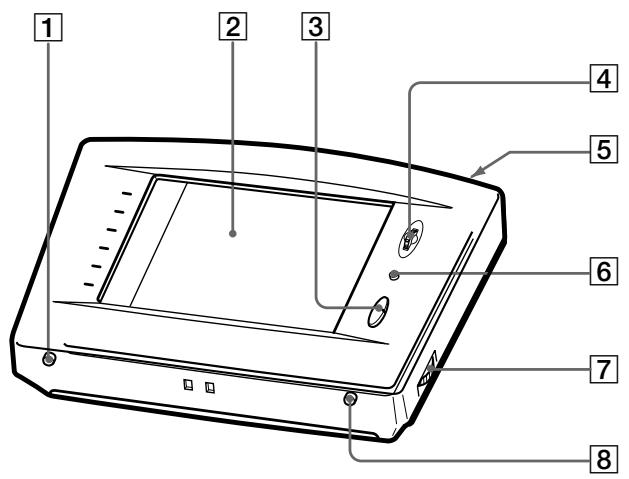
1 BACK LIGHT/COMMANDER OFF
Press to turn the backlight on or off. Hold down for about 2 seconds to turn the LCD off. When the LCD is off, press to turn on the LCD and backlight.
- To prolong use of the batteries, the LCD automatically turns off if there are no commands entered in the touch panel for 10 seconds.
- To view the LCD display without turning on the backlight, touch the touch panel when both the backlight and LCD are off.
2 Touch panel
Touch to operate. The commander turns on automatically.
3 VOL +/- buttons
Use to adjust the volume of the receiver/amplifier.
4 JOG DIAL control
Rotate to scroll through items in a list (etc.). Push to select the highlighted item.
5 SYSTEM STANDBY button
Normally used to turn off all Sony components. Can also be used to turn the receiver/amplifier on or off depending on the settings made in the SETUP screen (see page 30).
6 MUTING button
Use to mute the sound of the receiver/amplifier.
7 CONTRAST control
Use to adjust the contrast of the LCD.
8 SLEEP button
Use to operate the receiver/amplifier's sleep function. The sleep settings appear in the receiver/amplifier's display, not the commander's LCD.
Rear panel
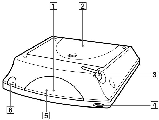
1 Transmitter/receiver section
Transmits and receives infrared signals to and from the receiver/amplifier.
2 Battery cover
3 Touch pen
4 SYSTEM STANDBY button
Normally used to turn off all Sony components. Can also be used to turn the receiver/amplifier on or off depending on the settings made in the SETUP screen (see page 30).
5 Remote code receiver section
When using the Learning function, this section receives the remote codes from other remote controls.
6 Touch pen holder
Pull out and insert touch pen when not in use.
Operation
This chapter explains how to operate the receiver/amplifier and connected audio/video components.
Basic Operations
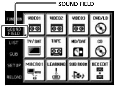
Displaying the FUNCTION screen
To operate components connected to the receiver/amplifier, first display the FUNCTION screen, then select the component you wish to operate (CD, MD, etc.).
Normally, the FUNCTION screen is displayed. If it is not displayed, touch FUNCTION to display it.
Touch FUNCTION in the LCD.
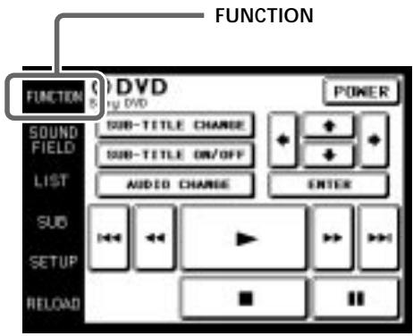
The FUNCTION screen appears.
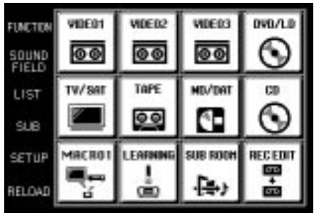
Composition of the FUNCTION screen is shown on the next page.
You can change the functions displayed in the FUNCTION screen
You can set all functions, except TUNER and REC EDIT, to be displayed or not, using the FUNCTION HOOK UP screen (see page 25).
FUNCTION screen hierarchy
The following diagram shows the composition of the FUNCTION screen hierarchy.
The types of icons that can be displayed on the FUNCTION screen can be set using FUNCTION HOOK UP in the SETUP screen. (For details on FUNCTION HOOK UP, see page 25.)
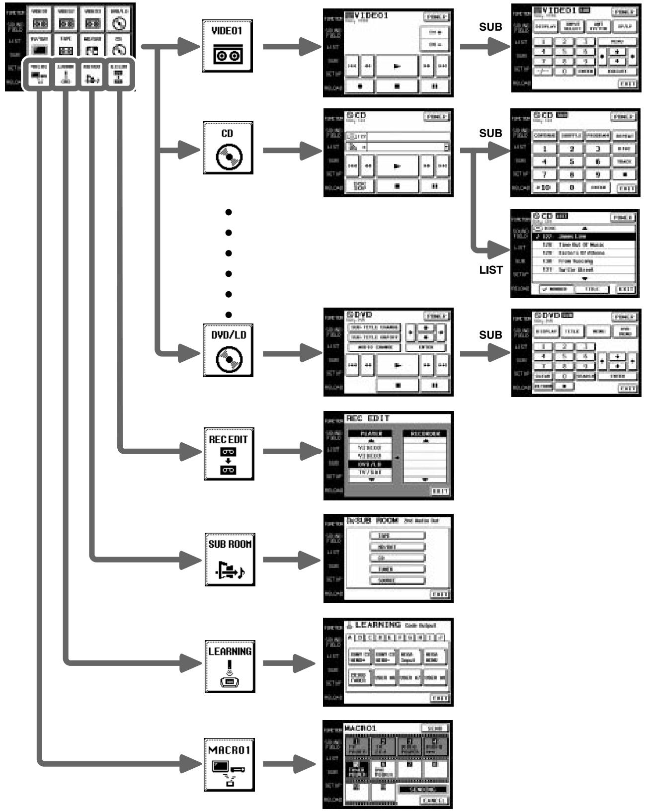
flowchart
graph TD
    A["Input Module"] --> B["VIDEO1"]
    A --> C["CD"]
    A --> D["..."]
    A --> E["DVD/LD"]
    A --> F["REC EDIT"]
    A --> G["SUB ROOM"]
    A --> H["LEARNING"]
    A --> I["MACRO1"]

    B --> J["VIDEO1"]
    C --> K["CD"]
    D --> L["..."]
    E --> M["DVD/LD"]
    F --> N["REC EDIT"]
    G --> O["Sub ROOM"]
    H --> P["LEARNING"]
    I --> Q["MACRO1"]

    J --> R["VIDEO1"]
    J --> S["CD"]
    J --> T["..."]
    J --> U["DVD"]
    J --> V["REC EDIT"]
    J --> W["Sub ROOM"]
    J --> X["LEARNING"]

    R --> Y["VIDEO1"]
    S --> Z["CD"]
    T --> AA["..."]
    T --> AB["DVD"]
    U --> AC["REC EDIT"]
    V --> AD["Sub ROOM"]
    W --> AE["LEARNING"]

    Y --> F
    Z --> G
    AA --> H
    AB --> I

    R --> S
    S --> T
    T --> U
    U --> V
    V --> W
    W --> X

    S --> X
    X --> Y
    Y --> Z
    Z --> W

    R --> Z
    Z --> AA
    AA --> AB
    AB --> AC
    AC --> AD
    AD --> AE
    AE --> AF
Example: Operating a CD Player
This section describes how to operate a CD player connected to the receiver/amplifier. Other components can also be operated in the same way.
For details concerning CD player operation, please refer to your CD player's operating instructions.
The screens used in the following example are the screens that appear when using a SONY CD changer with a CONTROL A1 II terminal.
1 Touch FUNCTION.
The FUNCTION screen appears.
2 Touch
The receiver/amplifier's function switches to CD and the CD screen appears.
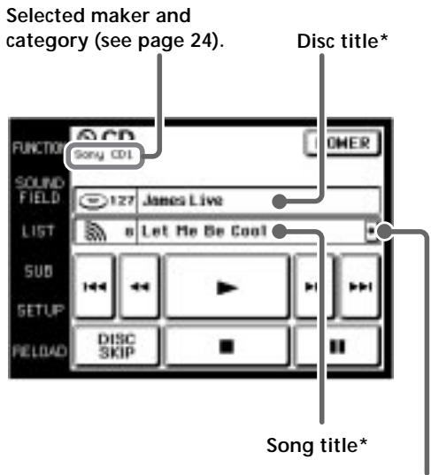
- Long titles can be read by touching the scroll icon (☐) to scroll along the title.
* Only displayed when a Sony CD changer (5/50/200/300 CD) or CD player compatible with CD text is connected to the receiver/amplifier by a CONTROL A1 cord.
3 Touch ▶ to start playback.
When the song number or song title is not displayed correctly Point the commander toward the receiver/amplifier and touch RELOAD.
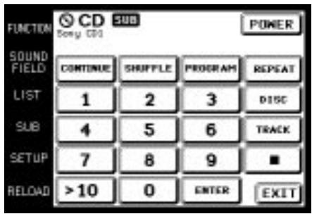
To operate other functions
Touch SUB or use the JOG DIAL to scroll. Another set of buttons is displayed and ready for use.
To view the LIST
Touch LIST to view the song titles in a Sony CD changer (5/50/200/300 CD) or MD deck connected by a CONTROL A1 cord. In this case, the information must be downloaded from the receiver/amplifier (see page 25 for details).
The LIST screen can only be displayed when the FUNCTION is set to CD or MD/DAT.
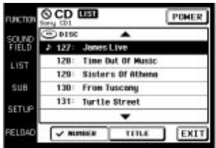
- Touch the disc number to start playing that disc. 🎨 appears next to the disc being played.
- Use the JOG DIAL or touch ▲ or ▼ to scroll up or down the list.
- Touch NUMBER to sort in numerical order or touch TITLE to sort in alphabetical order.
- Touch FUNCTION to return to the FUNCTION screen at any time.
Example: Operating the Tuner
This section describes how to operate the tuner. For details on tuner operation, please refer to the operating instructions provided with the receiver/amplifier.
1 Touch FUNCTION.
The FUNCTION screen appears.
2 Touch

The receiver/amplifier's function switches to TUNER and the tuner screen appears. However, preset station, station name, band, and frequency do not appear in the display of the amplifier.
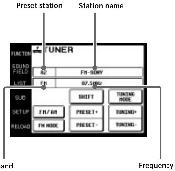
- Touch FM/AM to change the band.
- Touch FM MODE to switch the FM reception mode to AUTO or MONO. If the FM stereo reception is poor, select MONO. You will not be able to enjoy the stereo sound effect, but the sound will be less distorted.
- Touch PRESET + or – to search for preset stations.
- Touch TUNING + or – to search for stations that can be received.
- Touch SHIFT to switch memory pages (A, B, C).
- Touch TUNING MODE to switch the tuning mode to AUTO or MANUAL.
- During display of any of the screens, touching FUNCTION returns to the FUNCTION screen.

When broadcast stations or frequencies are not displayed perly
Point the commander at the receiver/amplifier and touch RELOAD.
To operate other functions
Touch SUB or use the JOG DIAL to scroll to display the icons used for memorizing broadcast stations and station names.
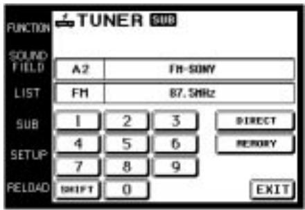
- To receive manually, touch DIRECT and input the frequency.
- When memorizing a received broadcast station, memorize after touching MEMORY.
Viewing the LIST
Touch LIST to view the names of the broadcast stations downloaded from the receiver/amplifier (see page 25 for details).
The LIST screen can only be displayed when the FUNCTION is set to TUNER.
Example: Recording from CD to MD
This section describes how to record audio from a CD to an MD as an example of recording audio/video.
Other operations
Recording from a DVD to a video deck is basically the same procedure. For details on the buttons used in recording, refer to the operating instructions supplied with the receiver/amplifier and other components.
1 Touch FUNCTION.
The FUNCTION screen appears.
2 Touch
The REC EDIT screen appears.
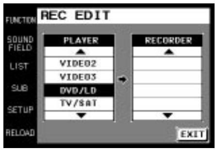
3 Touch to select the player component (CD in this example).
Because CD is not displayed, Use the JOG DIAL or touch ▼ to scroll downward through the list. If you scroll to far, touch ▲ to scroll back up.
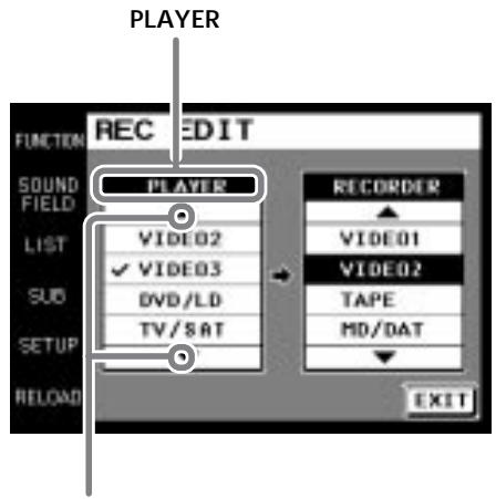
Touching ▲ moves list up Touching ▼ moves list down
When PLAYER is selected, the receiver/amplifier's function automatically switches to the PLAYER component.
4 Touch to select the recorder component (MD/DAT in this example).
When MD/DAT is touched, the REC EDIT operation screen appears.
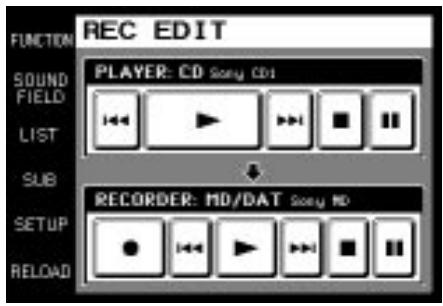
5 Touch ● in RECORDER: MD/DAT, then touch ▶ in PLAYER: CD.
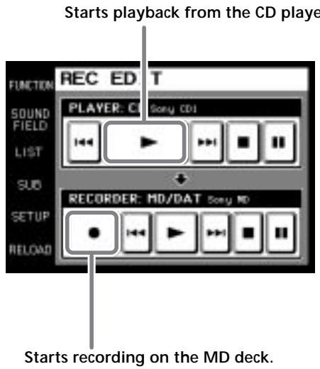
Recording starts.
The FUNCTION screen returns once the recording finishes.
To stop recording at any time
Although recording stops automatically in the above example, recording can also be stopped at any time by touching ■ in RECORDER.
To stop the recording procedure at any time
Touch FUNCTION to display the FUNCTION screen. During steps 2 to 3, touching EXIT will also stop the recording procedure.
Performing Several Commands in Sequence Automatically (Macro Play)
The Macro Play function lets you link several IR codes in sequential order as a single command. The remote provides 3 macro lists (MACRO 1, 2 and 3). You can specify up to 10 IR commands for each macro list.
1 Touch FUNCTION.
The FUNCTION screen appears.
2 Touch

The MACRO screen appears.
When does not appear in the FUNCTION screen, use the JOG DIAL to scroll through the list until it is displayed, and then touch it.
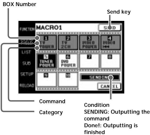
- Touch SEND to operate Macro Play. The current command is displayed in black. The finished commands are grayed out.
- To cancel Macro Play, touch CANCEL. When Macro Play is not operating, touching CANCEL returns to the FUNCTION screen.
Notes
- For some models, the receiver/amplifier cannot operate the Macro Play commands as the time between each command is too short. In this case, set “WAIT TIME” between each command. To set “WAIT TIME”, refer to “Macro Play setting” on page 26 and 27.
- For some makers other than Sony, there are some commands that cannot be used in Macro Play.
Using a command that has been learned
By using the Learning function, it is possible for this commander to perform learned operations. For details on how to learn the operation codes of other components using the Learning function, see page 29.
1 Touch FUNCTION.
The FUNCTION screen appears.

2 Touch
When does not appear in the screen, use the JOG DIAL to scroll the screen until it is displayed, and then touch it.
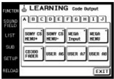
3 Touch the appropriate area from A to J corresponding to the learned command.
4 Touch the box containing the code you want to send.
A mark (■) appears in the box when it has already learned a command.
Selecting a source to listen to using SUB ROOM
Select a source that you would like to enjoy listening to in another room. You can switch the audio output to the 2nd AUDIO OUT on the receiver/amplifier. For details, please refer to the operating instructions supplied with your receiver/amplifier.
1 Touch FUNCTION.
The FUNCTION screen appears.

2 Touch
When does not appear on the screen, use the JOG DIAL to scroll the screen until it is displayed, and then touch it.
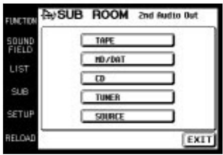
3 Touch the source that you want to listen to in another room.
The audio output on the receiver/amplifier changes.
Selecting Sound Fields
These sections describe how to select and make adjustments to the sound fields.
For details concerning sound fields, please refer to the operating instructions supplied with the receiver/amplifier.
Displaying the SOUND FIELD screen
Touch SOUND FIELD.
The SOUND FIELD screen appears.
The SOUND FIELD screen hierarchy is shown on the right.
SOUND FIELD screen hierarchy
EQ BANK

S.F. PRESET
Sound Field Mode

SP SETUP
CUSTOM
LEVEL
SURR EDIT
EQ EDIT
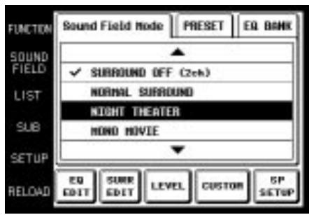
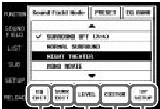
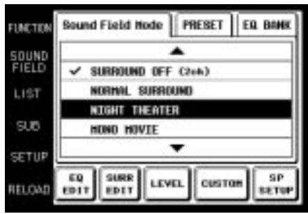
Selecting the sound field
For details concerning which sound fields can be selected, please refer to the operating instructions supplied with the receiver/amplifier.
1 Touch SOUND FIELD.
The SOUND FIELD screen appears.
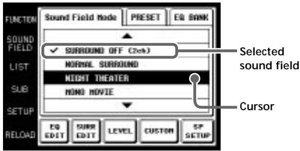
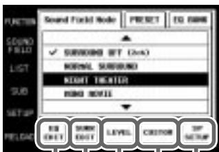
2 Touch Sound Field Mode.
The Sound Field Mode screen appears.
3 Use the JOG DIAL or touch ▲ or ▼ to scroll through the list.
4 Push the JOG DIAL to select the highlighted sound field or touch the sound field you desire. A check (√) will appear next to the selected sound field, and the sound field will change.
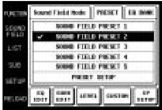
Selecting the sound field preset
1 Touch SOUND FIELD.
The SOUND FIELD screen appears.
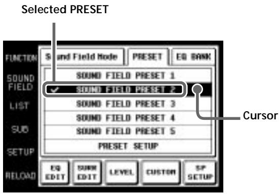
2 Touch PRESET.
The SOUND FIELD PRESET screen appears.
3 Touch one of the sound field presets (PRESET 1\~5). A check (√) will appear next to the selected sound field, and the sound field will change.
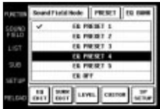
Selecting the equalizer
1 Touch SOUND FIELD. The SOUND FIELD screen appears.
2 Touch EQ BANK. The EQ BANK screen appears.
3 Touch one of the equalizer presets (EQ PRESET 1\~5). Touch EQ OFF to turn the receiver/amplifier's equalizer off. A check (√) will appear next to the selected equalizer, and the equalizer settings will change.
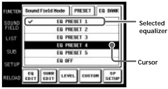
Note If EQ OFF is selected, EQUALIZER screen settings cannot be changed.
Setting the sound field preset
1 Touch SOUND FIELD.
The SOUND FIELD screen appears.
2 Touch PRESET.
The SOUND FIELD PRESET screen appears.
3 Touch PRESET SETUP. The SOUND FIELD PRESET SETUP screen appears.
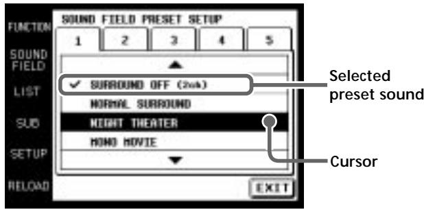
4 Use the JOG DIAL or touch ▲ or ▼ to scroll through the list.
5 Push the JOG DIAL to select the highlighted sound field or touch the sound field you desire. A check (√) will appear next to the selected sound field, and the sound field will change.
Adjusting Sound Fields
Set up the SOUND FIELD screen menus to fully enjoy the surround sound created by the sound fields.
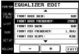
On the EQ EDIT screen, adjust the frequency bands of front, center and rear speakers of the equalizer preset (EQ PRESET 1-5) that you selected on the EQ BANK screen.
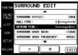
Adjust various aspects of individual sound fields on the SURROUND screen. The settings are stored individually for each sound field.
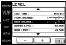
Adjust the output level of each speaker and perform a variety of other adjustments to control the sound mix on the LEVEL screen.
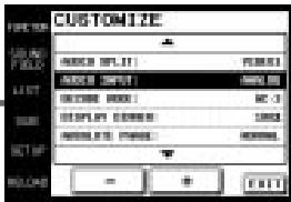
CUSTOM allows you to customize other operations that the amplifier/receiver performs. For details on what can be adjusted, refer to the operating instructions supplied with the amplifier/receiver.
Set speaker configuration, size and distance from the main listening position on the SP SETUP screen.
Adjusting the frequency bands
1 Touch EQ EDIT on the SOUND FIELD screen.
The EQUALIZER screen of the equalizer preset selected in the EQ BANK screen appears.
If EQ OFF is selected in the EQ BANK screen, EQUALIZER screen items are all grayed out, and edit functions cannot be performed.
2 Use the JOG DIAL or touch ▲ or ▼ to scroll through the list.
3 Push the JOG DIAL to select an item or touch the item you want to adjust.
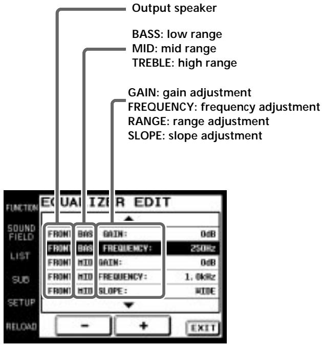
4 Touch + or - to adjust to the desired value.
5 Repeat steps 2 through 4 when there is more than one item that you wish to adjust.
6 Touch EXIT when adjustment is finished.
Notes
- Items that cannot be adjusted due to the current speaker settings or sound field mode are grayed out.
- If the alarm sounds, or all items appear to be grayed out, touch RELOAD.
Adjusting the surround parameters
1 Touch SURR EDIT on the SOUND FIELD screen. The SURROUND screen appears.
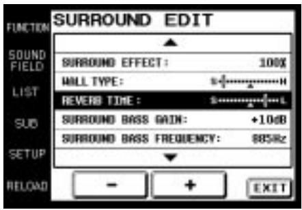
2 Use the JOG DIAL or touch ▲ or ▼ to scroll through the list.
3 Push the JOG DIAL to select an item or touch the aspect you want to adjust.
4 Touch + or - to adjust to the desired value.
SURROUND EFFECT: Higher values increase the “presence” of the surround effect.
WALL TYPE: Use to simulate different sonic environments.
REVERB TIME: Use to control the spacing of the early reflections to simulate a larger or smaller room.
SCREEN DEPTH: Use to control the extent to which the sound appears to be coming from within the screen.
VIRTUAL SPEAKERS: Use to set whether to use the virtual speakers or not.
Tone quality adjustments: Use these parameters to adjust the overall sound quality of the selected sound field.
5 Repeat steps 2 through 4 when there is more than one aspect that you wish to adjust.
6 Touch EXIT when adjustment is finished.
Notes
- Items that cannot be adjusted due to the current speaker settings or sound field mode are grayed out.
- If the alarm sounds, or all items appear to be grayed out, touch RELOAD.
Adjusting the speaker levels
1 Touch LEVEL on the SOUND FIELD screen. The LEVEL screen appears.
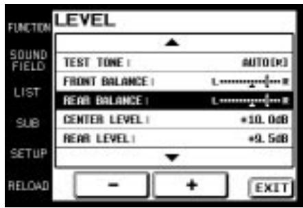
2 Use the JOG DIAL or touch ▲ or ▼ to scroll through the list.
3 Push the JOG DIAL to select an item or touch the item you want to adjust.
4 Touch + or - to adjust.
5 Repeat steps 2 through 4 when there is more than one item that you wish to adjust.
6 Touch EXIT when adjustment is finished.
To adjust the speaker balance
Use TEST TONE to listen to the levels output from each speaker. AUTO outputs the test tone to each speaker in order. You can also select individual speakers to output the test tone. Adjust your speaker levels so that the test tone is output at the same level from all speakers.
Notes
- Items that cannot be adjusted due to the current speaker settings or sound field mode are grayed out.
- If the alarm sounds, or all items appear to be grayed out, touch RELOAD.
Customizing other receiver/amplifier operations
1 Touch CUSTOM on the SOUND FIELD screen. The CUSTOMIZE screen appears.
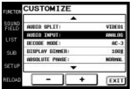
2 Use the JOG DIAL or touch ▲ or ▼ to scroll through the list.
3 Push the JOG DIAL to select an item or touch the item you want to set.
4 Touch + or - to adjust settings.
5 Repeat steps 2 through 4 when there is more than one item that you wish to adjust.
6 Touch EXIT when adjustment is finished.
Notes
- Items that cannot be adjusted due to the current speaker settings or sound field mode are grayed out.
- If the alarm sounds, or all items appear to be grayed out, touch RELOAD.
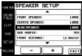
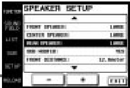
Adjusting the speaker settings
1 Touch SP SETUP on the SOUND FIELD screen. The SPEAKER SETUP screen appears.
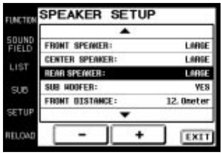
2 Use the JOG DIAL or touch ▲ or ▼ to scroll through the list.
3 Push JOG DIAL to select a parameter or touch the parameter you want to adjust.
4 Touch + or - to adjust to the desired setting.
5 Repeat steps 2 through 4 when there is more than one parameter that you wish to adjust.
6 Touch EXIT when speaker setup is finished.
Notes
- Items that cannot be adjusted due to the current speaker settings or sound field mode are grayed out.
- If the alarm sounds, or all items appear to be grayed out, touch RELOAD.
Adjusting the Commander's Operating Environment
The following explanations allow you to adjust various settings and customize the commander's operating environment.
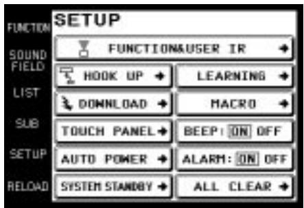
Displaying the SETUP screen
To adjust the operating environment, first display the SETUP screen.
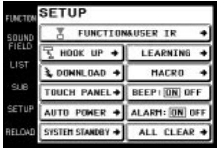
Touch SETUP.
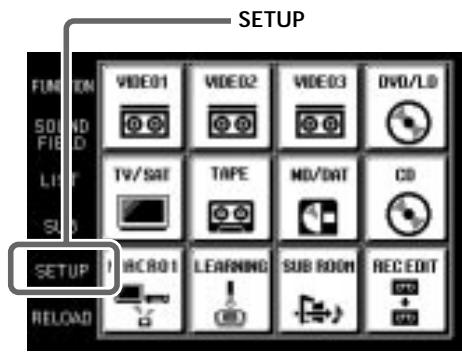
The SETUP screen appears.
Registering the connected components
The following procedure lets you set up the commander to operate the components connected to the receiver/amplifier.
When carrying out this operation, make sure that the receiver/amplifier's power is on, and be sure to point the commander's transmitter/receiver section toward the display on the receiver/amplifier.
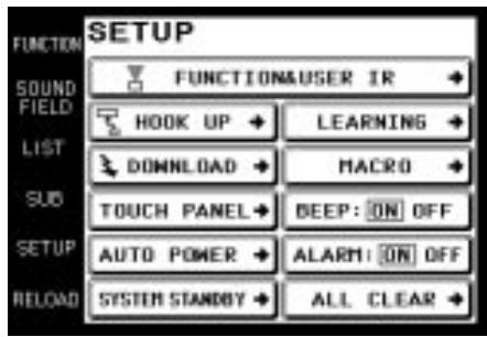
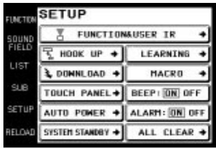
1 Touch SETUP.
The SETUP screen appears.
2 Touch FUNCTION&USER IR.
The FUNCTION&USER IR screen appears.
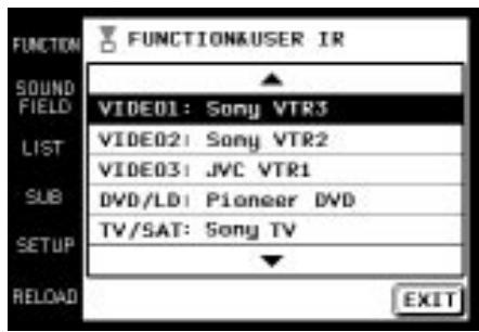
3 Select the function that you wish to register (Ex: VIDEO1).
To display other items, use the JOG DIAL or touch ▲ or ▼ to scroll through the list.
The FUNCTION&USER IR:CATEGORY screen appears.
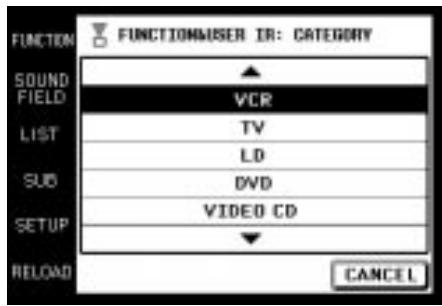
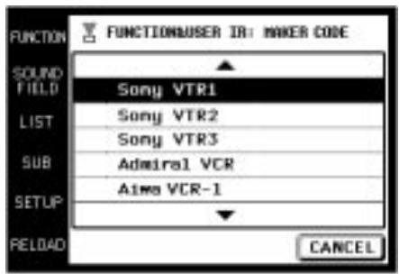
4 Select the type of component connected (Ex: VCR). To display other items, use the JOG DIAL or touch ▲ or ▼ to scroll through the list. The FUNCTION&USER IR:MAKER CODE screen appears.
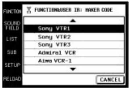
5 Touch the remote controller mode of the connected component (Ex: Sony VTR1).
The component selected in steps 4 to 5 will be registered at the function selected in step 3, and the SETUP screen reappears. A long beep sound is emitted to indicate that registration was successful. Operation is now possible from the FUNCTION screen. If a series of short beeps is emitted, redo the registration procedure. If this occurs, make sure the receiver/amplifier is turned on and that the commander is pointing toward the receiver/amplifier during operation.
To stop registration at any time
Touch EXIT during step 2 or touch CANCEL during steps 3 to 5.
Notes
- All icons may not be displayed when registering components made by certain manufacturers.
- Some commands may not function even though they are displayed when registering components made by certain manufacturers.
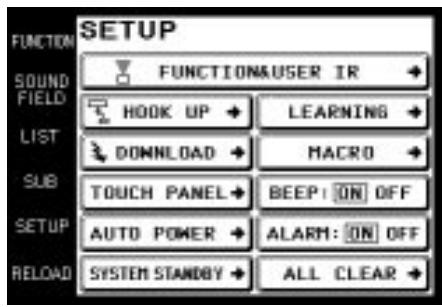
FUNCTION screen setup
You can set the FUNCTION screen not to display components you do not use.
1 Touch SETUP.
The SETUP screen appears.
2 Touch FUNCTION HOOK UP.
The FUNCTION HOOK UP screen appears.
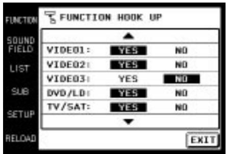
3 Select the function not to be displayed and touch NO.
To display other items, use the JOG DIAL or touch ▲ or ▼ to scroll through the list.
The selected component is set not to appear and the SETUP screen reappears.
To display the components set not to be displayed Touch YES instead of NO in step 3.

Components that have been registered (see page 24) are set YES" automatically.
Note
When a function does not appear in the display even though FUNCTION HOOK UP is set to YES, turn the JOG DIAL to display the function.
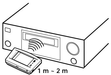
Downloading receiver/amplifier data
Various types of data can be downloaded from the receiver/amplifier.
When carrying out this operation, make sure that the receiver/amplifier's power is on, and be sure to point the commander's transmitter/receiver section toward the display on the receiver/amplifier. Also, operate the commander at a distance of about 1\~2 meters from the receiver/amplifier.
1 Touch SETUP.
The SETUP screen appears.
2 Touch DOWNLOAD.
The DOWNLOAD screen appears.
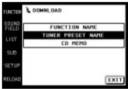
"TUNER PRESET NAME" does not appear in the case of an amplifier.
3 Touch to select the data you wish to download and press:
FUNCTION NAME: Names of connected components. TUNER PRESET NAME: Broadcast station names etc., memorized in receiver. This is not displayed in case of amplifier.
CD MEMO: CD song titles or disc titles etc., from a Sony CD changer (5/50/200/300 CD) connected to the receiver/amplifier with CONTROL A1 cord.
Downloading starts, and the progress is displayed. During this time, please leave the commander's transmitter/receiver section pointed toward the display on the receiver/amplifier.
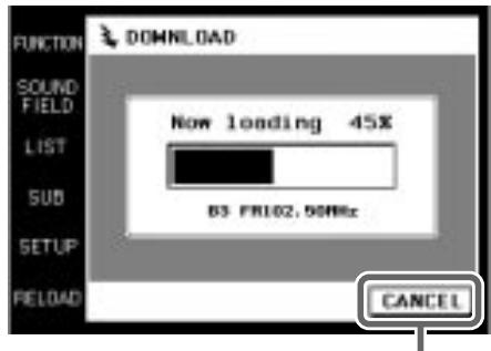
When you touch CANCEL, the data downloaded before you touched CANCEL will be saved.
When downloading has finished, the DOWNLOAD screen reappears. A long beep sound is emitted to indicate that the downloading was successful. If a series of short beeps is emitted, redo the downloading procedure. If this occurs, make sure the receiver/amplifier is turned on and that the commander is pointing toward the receiver/amplifier during operation.
4 Repeat step 3 to download other data.
5 Touch EXIT.
Downloading finishes and the SETUP screen reappears.
Macro Play setting
The following is an example of how to set the command “POWER” for SONY VTR 1 in BOX 2 of MACRO 1. Set other commands in a similar manner.
1 Touch SETUP.
The SETUP screen appears.
2 Touch MACRO.
The setting screen for Macro Play appears.
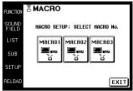
3 Select the MACRO Number.
Select MACRO 1, MACRO 2 or MACRO 3 in which you want to register the macro program. For example, select MACRO 1.
The BOX Number list appears.
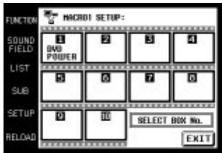
4 Select the BOX Number.
Select the BOX Number you want to register the command. You can program up to 10 commands in one area.
The CATEGORY list appears.

5 Select the CATEGORY.
Select the component category for the BOX Number you selected in step 4.
The MAKER list appears according to the category you selected.
When the maker is Sony only, go to step 7.
You can select "WAIT TIME" other than audio components as the CATEGORY.
6 Select the MAKER.
Select the maker from the maker list.
The COMMAND list appears according to the maker you selected.
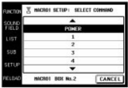
7 Select the COMMAND.
Select the command you want to register.
The items selected in step 5 to 7 are registered in the box selected in step 4.
The BOX Number list reappears.

To clear the programmed MACRO
Select the BOX Number of the MACRO you want to clear in step 4. Select “MACRO CLEAR” in the CATEGORY in step 5. The items of the BOX are cleared.

To set "WAIT TIME"
Select the BOX Number of the MACRO you want to set the wait time for in step 4. Select "WAIT TIME" in the CATEGORY in step 5.
The wait time list (1 to 10 second in 1 second increments) appears. Select the time you want to delay. After you selected, the BOX Number list reappears.
If you press ALL CLEAR on the receiver/amplifier, all the registered MACRO programs are cleared.
Setting the function name
1 Touch SETUP.
The SETUP screen appears.
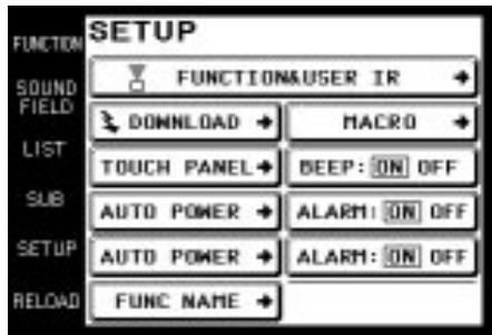
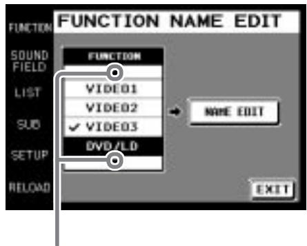
2 Touch FUNC NAME.
The FUNCTION NAME EDIT screen appears. If FUNC NAME does not appear in the display, use the JOG DIAL to scroll the screen until FUNC NAME appears.
Touching ▲ moves list up
Touching ▼ moves list down
3 Touch the function that you want to edit.
4 Touch NAME EDIT.
The NAME EDIT screen appears.
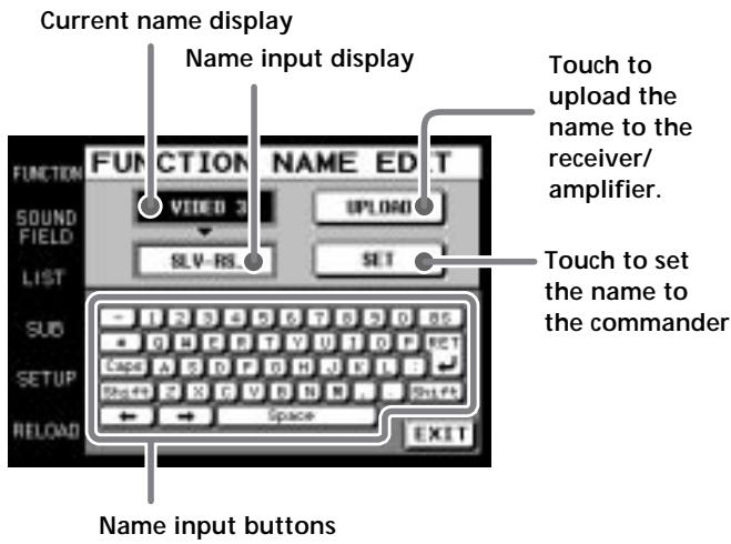
5 Enter the name.
After the name has been entered, touch SET. The new function name is set in the commander. After the name has been entered, point the commander toward the receiver/amplifier and touch UPLOAD. The new function name is set in the receiver/amplifier.
Setting remote control codes that are not stored in the commander
When a remote control code is not one of the presets stored in the commander, it is possible for the commander to learn the code using the Learning function. For details on how to use the learned codes, please see page 17.
1 Touch SETUP.
The SETUP screen appears.
2 Touch LEARNING.
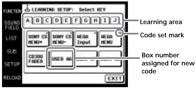
3 Touch the area corresponding to where you want the new code to be learned. Any letter from A to J can be selected (for example, select "A").
4 Touch the Box Number where you want to save the new code (for example, select "A6").
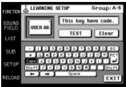
The LEARNING SETUP screen is displayed.
Box number assigned for new code
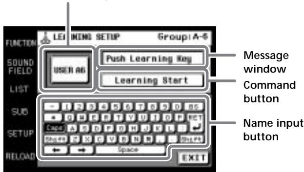
5 Touch "Learning Start".
"Please Send Signal" is displayed.
6 Point the remote code receiver section of the commander toward the receiver/transmitter on the remote control to be learned.
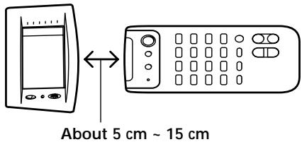
7 Press the appropriate button on the remote control to send the remote control code.
Lightly pressing the button once should be sufficient. In about 3 to 5 seconds, it is displayed whether learning was successful or not.
When learning is successful, “Learning OK!” is displayed, and a mark (■) will appear next to the selected box.
When learning is not successful, “Learning Fail..” is displayed, and 3 seconds later “Please Send Signal” is displayed again. Please do this procedure again from step 6.
To erase the learned code
After step 7, touch “Clear” and the display changes to “Clear?”. If “Yes” is touched at this time, the newly learned code is erased. If “No” is touched, the code is not erased, and the commander returns to its previous condition.
You can test the learned code
Touch “TEST” after “Learning OK” is displayed in step 7. The learned code is sent from the commander, and if correct, the operation corresponding to the learned code is performed.
You can make a name of up to 14 characters for the learned code
Touch name input buttons as displayed in step 4 to enter the name.
Notes
- Normally, in the areas from A to J, there is a total of 80 BOX Numbers that can be used with the Learning function. However, depending on the signals of the codes being learned, it may not be possible for the commander to store codes for all 80 BOX Numbers.
- To learn commands such as volume, fast-forward, rewind (etc.) that are generally performed by continuously pressing the button, press and hold the button until “Learning OK” appears in step 7. For other commands such as play, pause, and stop (etc.) where continuously holding the button is not necessary, learning is usually possible by pressing the button once.
- Some remote control codes cannot be learned.
Other setup
■ Adjusting the position of the touch panel (LCD)
Adjust the position of the LCD when it shifts from the normal operating position.
1 Touch TOUCH PANEL on the SETUP screen. The TOUCH PANEL ADJUSTMENT screen appears.
2 Touch the center of each of the 4 dots. (For details, see “Touch panel adjustment” on page 6.) “Adjusted” appears in a short while and long beep is emitted.
■ Setting the AUTO POWER function
ON: When a video function (DVD, etc.) is selected, the commander sends numerous codes to the appropriate Sony AV components. At this time, the TV automatically switches to VIDEO 1 input mode.* Example) When you select DVD, the following occurs.
1 The receiver/amplifier switches to DVD player operation mode.
2 The TV turns on.
3 The DVD player turns on.
4 The TV automatically selects VIDEO 1 input.
OFF: When a function is selected, the commander code applies only to receiver/amplifier operation.
* Switching to VIDEO 1 input may not be automatic on all Sony TVs. This is because some TVs cannot receive remote control codes immediately after being turned on.
■ Changing the function of the SYSTEM STANDBY button
ALL OFF: Switches power of all Sony AV components off.
ON/OFF: Switches only the receiver/amplifier on or off.
■ Setting the operation beep sound on or off
A beep can be set to sound or not sound when the touch panel is touched.
Touch ON (sound) or OFF (no sound) in BEEP:ON OFF in the SETUP screen.
■ Setting the warning alarm on or off
A warning alarm can be set to sound or not sound when a communication error has occurred.
Touch ON (sound) or OFF (no sound) in ALARM:ON OFF in the SETUP screen.
■ Returning settings to their factory preset settings
Use this function to erase all memorized settings and return them to their factory presets.
Please note that once erased, settings cannot be returned.
When carrying out this operation, make sure that the receiver/amplifier's power is on, and be sure to point the commander's transmitter/receiver section toward the display on the receiver/amplifier.
1 Touch ALL CLEAR on the SETUP screen.
2 Touch YES.
■ CONTROL A1 auto function (AUTO FUNC)
ON: When a component connected via a CONROL A1 cord is played, the power to this unit is turned on and the function selector is automatically set for that component. OFF: When you do not want linked control of connected components, select [OFF]. When AUTO FUNC does not appear in the display, use the JOG DIAL to scroll the screen until AUTO FUNC appears.
Additional information
Precautions during use
On installment
Do not drop the commander or subject it to strong vibration as this could cause damage.
On the touch pen
Use only the touch pen provided with this unit or the soft tip of your finger to operate the touch panel. Using a commercially available writing utensil may damage the panel and make correct operation impossible. If the tip of the touch pen is damaged, or the touch pen is lost, please consult your nearest Sony dealer.
On battery life
When the backlight is not necessary, do not press BACK LIGHT/COMMANDER OFF to turn on the LCD. Touch the touch panel to turn on just the LCD. The life of the battery will be prolonged. The life of the battery may be shortened depending on the conditions in which the commander is used.
On handling
The touch panel (display section) is made of glass. Twisting the touch panel, dropping the unit, placing your elbow (etc.) on it, or placing heavy objects on top of it, may break the touch panel and cause bodily harm due to glass fragments.
On cleaning
Clean the cabinet, panel and controls with a soft cloth slightly moistened with a mild detergent solution. Do not use solvent such as thinner, benzine, or alcohol as these will damage the surface of the commander.
Troubleshooting
If you experience any of the following difficulties while using the commander, use this troubleshooting guide to help you remedy the problem. Should any problem persist, consult your nearest Sony dealer.
Operation can not be done with the commander.
→ Check that the receiver/amplifier and components are connected correctly.
→ The commander and receiver/amplifier are too far apart.
→ Make sure that there are no objects between the commander and receiver/amplifier.
→ Make sure that the receiver/amplifier's power is turned on.
The commander's transmitter/receiver section is not pointed at the receiver/amplifier.
The commander's batteries are exhausted. Replace with new alkaline batteries (see page 7).
→ There is an inverter system florescent light near the commander or receiver/amplifier. Please place away from the florescent light.
→ Make sure you have selected the correct function on the remote.
→ When you operate a programmed non-Sony component, the remote may not function properly depending on the make and model of the component.
The receiver/amplifier's functions and modes do not correlate with the displays on the commander.
→ Initial communication setup has not been done. Use after first carrying out initial communication setup (see page 6).
→ The commander was not pointed at the receiver/amplifier when it was turned ON. Touch RELOAD, and download component data (see page 8).
→ Select the correct function using the commander.
LCD does not appear.
→ The LCD is not turned on. Touch the touch panel.
→ Contrast is too light or too dark.
Use the CONTRAST control to adjust the contrast of the LCD (see page 6).
When a CD player, tape deck, or MD deck is connected to the receiver/amplifier via CONTROL A1Ⅱ jacks, Auto Function does not work properly.
→ Reprogram the remote (see page 30).
The SOUND FIELD function does not work.
→ If the receiver/amplifier has the 5.1 INPUT jacks, the SOUND FIELD function becomes inoperable whenever you select the component connected to the jacks.
Commands of components made by manufacturers other than Sony do not function.
→ When registering components made by certain manufacturers, some commands may not function even though they are displayed.
"5.1 INPUT" cannot be selected from the function screen even though the receiver/amplifier has the 5.1 INPUT jacks.
→ A communication error has occurred. Point the remote towards the receiver/amplifier and select "5.1INPUT" from the function screen again.
Specifications
Operating system
Liquid crystal touch panel
Liquid crystal size
3.8 inches
(256 x 200 dots)
Liquid crystal type
Reflection system
(Monochrome type)
Touch panel
Resistant membrane system
Analog type
Power requirements
For operation: DC 6V
(Type AA alkaline
batteries)
For memory
preservation:
DC 3V
(CR2032 lithium
battery)
Maximum external dimensions
(width x height x depth, including
projecting parts and controls)
160 x 111 x 46 mm
Mass
290 g (Main unit only
including touch pen)
Design and specifications are subject to change without notice.
Index
A, B
Battery 5,7
C
CD player 13
D
Downloading receiver/amplifier
data 25
E, F, G
Front panel 9
FUNCTION Screen 11, 12
setup 25
H, I, J, K, L
Operating components
CD player 13
Recording 15
Tuner 14
M, N, O
Macro Play 16, 26, 27
P, Q, R
Rear panel 10
Recording 15
Registering the connected
component 24
S
Setup
commander 6
environment 24\~30
FUNCTION screen 25
SETUP screen 24
SOUND FIELD 18\~20
T, U, V, W, X, Y, Z
Tuner 14
Précautions
ATTENTION (pile au lithium)
natural_image
Line drawing of a device casing with a handle and internal components, no text or symbols presentRemarques
1 Retirez le crayon tactile.
Commande CONTRAST
natural_image
Line drawing of a portable electronic device with a sensor array and a handheld device (no text or symbols)1 m \~ 2 m
Remarques
Remplacez les piles alcalines.
Remplacez la pile au lithium.
natural_image
Line drawing of a hand using a screwdriver to adjust or install a component on a device (no text or symbols visible)Remarques
1 BACK LIGHT/COMMANDER OFF
2 Touchez

2 Touchez

SP SETUP
2 Touchez FUNC NAME.
4 Touchez NAME EDIT.
Lecture de macro 16, 26, 27
P, Q
Panneau avant 9
Panneau arrière 10
Piles 5, 7
R
natural_image
Line drawing of a mechanical device with a curved top component and internal components (no text or symbols)Notas
Control CONTRAST
natural_image
Line drawing of a portable electronic device with a sensor array and a handheld device, labeled '1 m ~ 2 m' (no text or symbols on the device itself)Notas
natural_image
Illustration of hands using a screwdriver to insert or install an electronic component (no text or symbols visible)Notas
flowchart
```mermaid
graph TD
    A["Input Device"] --> B["Video01"]
    A --> C["CD"]
    A --> D["..."]
    A --> E["DVD/LD"]
    A --> F["REC EDIT"]
    A --> G["SUB ROOM"]
    A --> H["LEARNING"]
    A --> I["MACR01"]

    B --> J["Sub-Visual Interface"]
    C --> K["Sub-Visual Interface"]
    D --> L["Sub-Visual Interface"]
    E --> M["Sub-Visual Interface"]
    F --> N["Sub-Visual Interface"]
    G --> O["Sub-Visual Interface"]
    H --> P["Sub-Visual Interface"]
    I --> Q["Sub-Visual Interface"]

    J --> R["Sub-Display Interface"]
    K --> S["Sub-Display Interface"]
    L --> T["Sub-Display Interface"]
    M --> U["Sub-Display Interface"]
    N --> V["Sub-Display Interface"]
    O --> W["Sub-Display Interface"]
    P --> X["Sub-Display Interface"]

    style A fill:#f9f,stroke:#333
    style I fill:#f9f,stroke:#333

    %% Note: The image contains only a diagram of a system with multiple labeled blocks (e.g., Video01, CD, DVD/LD) and connections to corresponding visual interfaces. The numbers 1–5 in the image are not explicitly provided in the code.
2 Toque
2 Toque
natural_image
Line drawing of a device with a lid and internal components, no text or symbols presentNotas
Controlo CONTRAST
Ajustamento do painel de toque
natural_image
Line drawing of a device with a sensor array and a handheld device (no text or symbols)Nota
natural_image
Illustration of a hand using a screwdriver to insert or install a component on a device (no text or symbols visible)Notas
1 BACK LIGHT/COMMANDER OFF
2 Toque em
2 Toque em
3 Toque na fonte que pretende escutar num outro recinto.
O écran SOUND FIELD aparece.
Sound Field Mode
O écran SETUP aparece.
Adjusting the Commander's Operating Environment
Notas
ON: When a component connected via a CONROL A1 cord is played, the power to this unit is turned on and the function selector is automatically set for that component.
OFF: When you do not want linked control of connected components, select OFF.
- CAUTION (Lithium battery)
- About This Manual
- Before You Use the Commander
- Understanding the 2 way remote system
- Special Remarks
- ■ About the LCD
- ■ About batteries
- Life span of the batteries
- TABLE OF CONTENTS
- Preparations 4
- Location of Parts and Basic Operations 9
- Operation 11
- Additional information 31
- Preparations
- Compatible Components and Functions
- Compatible Components
- Functions
- Preparing the Commander
- Inserting batteries into the commander
- Remove the battery compartment cover.
- Insert the alkaline batteries.
- Insert the lithium battery.
- Close the battery compartment cover.
- Notes
- Setting up the commander
- Remove the touch pen.
- Caution
- Turn CONTRAST to adjust brightness of the LCD.
- Touch panel adjustment
- Initial communication
- If a communication error occurs during setup
- Note
- When replacing the batteries
- When to replace batteries
- Screen Hierarchy
- Location of Parts and Basic Operations
- Front panel
- BACK LIGHT/COMMANDER OFF
- Touch panel
- VOL +/- buttons
- JOG DIAL control
- SYSTEM STANDBY button
- MUTING button
- CONTRAST control
- SLEEP button
- Rear panel
- Operation
- Basic Operations
- Displaying the FUNCTION screen
- FUNCTION screen hierarchy
- Example: Operating a CD Player
- Touch FUNCTION.
- Touch
- Touch ▶ to start playback.
- To operate other functions
- To view the LIST
- Example: Operating the Tuner
- Viewing the LIST
- Example: Recording from CD to MD
- Other operations
- Touch to select the player component (CD in this example).
- Touch to select the recorder component (MD/DAT in this example).
- Touch ● in RECORDER: MD/DAT, then touch ▶ in PLAYER: CD.
- To stop recording at any time
- To stop the recording procedure at any time
- Performing Several Commands in Sequence Automatically (Macro Play)
- Using a command that has been learned
- Selecting a source to listen to using SUB ROOM
- Touch the source that you want to listen to in another room.
- Selecting Sound Fields
- Displaying the SOUND FIELD screen
- Selecting the sound field
- Selecting the sound field preset
- Selecting the equalizer
- Setting the sound field preset
- Adjusting Sound Fields
- Adjusting the frequency bands
- Adjusting the surround parameters
- Adjusting the speaker levels
- To adjust the speaker balance
- Customizing other receiver/amplifier operations
- Adjusting the speaker settings
- Adjusting the Commander's Operating Environment
- Displaying the SETUP screen
- Registering the connected components
- FUNCTION screen setup
- Downloading receiver/amplifier data
- Touch DOWNLOAD.
- Touch to select the data you wish to download and press:
- Repeat step 3 to download other data.
- Touch EXIT.
- Macro Play setting
- Touch SETUP.
- Touch MACRO.
- Select the MACRO Number.
- Select the BOX Number.
- Select the CATEGORY.
- Select the MAKER.
- Select the COMMAND.
- Setting the function name
- Touch FUNC NAME.
- Touch the function that you want to edit.
- Touch NAME EDIT.
- Enter the name.
- Setting remote control codes that are not stored in the commander
- Touch LEARNING.
- Touch "Learning Start".
- Press the appropriate button on the remote control to send the remote control code.
- To erase the learned code
- You can test the learned code
- You can make a name of up to 14 characters for the learned code
- Other setup
- ■ Adjusting the position of the touch panel (LCD)
- ■ Setting the AUTO POWER function
- ■ Changing the function of the SYSTEM STANDBY button
- ■ Setting the operation beep sound on or off
- ■ Setting the warning alarm on or off
- ■ Returning settings to their factory preset settings
- ■ CONTROL A1 auto function (AUTO FUNC)
- Additional information
- Precautions during use
- On installment
- On the touch pen
- On battery life
- On handling
- On cleaning
- Troubleshooting
- Operation can not be done with the commander.
- The receiver/amplifier's functions and modes do not correlate with the displays on the commander.
- LCD does not appear.
- The SOUND FIELD function does not work.
- Commands of components made by manufacturers other than Sony do not function.
- "5.1 INPUT" cannot be selected from the function screen even though the receiver/amplifier has the 5.1 INPUT jacks.
- Specifications
- Index
- Précautions
- ATTENTION (pile au lithium)
- Remarques
- Retirez le crayon tactile.
- Touchez
- Touchez FUNC NAME.
- Touchez NAME EDIT.
- Notas
- Toque
- Ajustamento do painel de toque
- Nota
- Toque em
- Toque na fonte que pretende escutar num outro recinto.
Brand : SONY
Model : RM-TP503
Category : Remote control