Power TMS6RG - Car speaker Rockford Fosgate - Free user manual and instructions
Find the device manual for free Power TMS6RG Rockford Fosgate in PDF.
Document temporarily unavailable
The manual is currently being transferred to our new server. It will be accessible again in a few hours. Thank you for your patience.
| Product type | Car speaker |
| Brand | Rockford Fosgate |
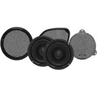
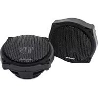
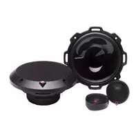
| Model | Power TMS6RG |
| Category | 2-way coaxial speaker |
| Diameter | 16.5 cm (6.5 inches) |
| RMS power | 75 Watts per channel |
| Peak power | 150 Watts |
| Impedance | 4 ohms |
| Frequency response | 50 Hz - 20 kHz |
| Sensitivity | 90 dB |
| Tweeter | 25 mm silk dome |
| Cone material | Injected polypropylene |
| Protective grille | Included (black metal grille) |
| Mounting depth | 55 mm |
| Cutout required | 142 mm |
| Weight | 1.2 kg (pair) |
| Warranty | 1 year |
| Included accessories | Mounting screws, connectors, grilles |
| Maintenance | Clean with a soft dry cloth |
| Repairability | Spare parts available through after-sales service |
Frequently Asked Questions - Power TMS6RG Rockford Fosgate
User questions about Power TMS6RG Rockford Fosgate
0 question about this device. Answer the ones you know or ask your own.
Ask a new question about this device
Download the instructions for your Car speaker in PDF format for free! Find your manual Power TMS6RG - Rockford Fosgate and take your electronic device back in hand. On this page are published all the documents necessary for the use of your device. Power TMS6RG by Rockford Fosgate.