
Modernist DOC30M977DS - Microwave Oven Dacor - Free user manual and instructions
Find the device manual for free Modernist DOC30M977DS Dacor in PDF.

| Product Type | Built-in combination microwave oven (microwave + lower oven) |
| Brand | Dacor |
| Model | Modernist DOC30M977DS |
| Height | 110.2 cm |
| Width | 75.7 cm |
| Depth | 58.7 cm |
| Weight | 130 kg |
| Electrical power supply | 240 V / 208 V, 60 Hz, 8.9 kW / 6.7 kW, dedicated 30 A circuit |
| Electrical connection | 4-wire or 3-wire depending on local codes, grounding required |
| Main functions | Microwave, lower oven (convection), grill, steam function, LED lighting |
| Installation type | Built into a cabinet, requires a complete cabinet |
| Door | Lower oven door removable, upper oven door non-removable |
| Safety | Child safety lock, automatic shut-off in case of overheating, self-diagnostic system |
| Maintenance and cleaning | Interior cleaning with soft cloth and mild detergent, removable racks, do not use abrasive cleaners |
| Spare parts and repairability | Parts available through Dacor customer service, repair by qualified technician |
| Maximum cabinet temperature | 194 °F (90 °C) for wooden cabinets |
| Electrical conduit length | 170 cm |
Frequently Asked Questions - Modernist DOC30M977DS Dacor
User questions about Modernist DOC30M977DS Dacor
0 question about this device. Answer the ones you know or ask your own.
Ask a new question about this device
Download the instructions for your Microwave Oven in PDF format for free! Find your manual Modernist DOC30M977DS - Dacor and take your electronic device back in hand. On this page are published all the documents necessary for the use of your device. Modernist DOC30M977DS by Dacor.
USER MANUAL Modernist DOC30M977DS Dacor
Installation Instructions
Modernist Built-In Microwave Combination Oven
DOC30M977D
Contents
Before you begin... 3
Important 3
Customer-assurance info 3
If You Need Help... 3
Important safety instructions 4
Related equipment safety 4
Transport 4
Installation requirements 5
Prepare to install the oven 6
Checklist 7
Location requirements 7
Product dimensions 8
Cabinet dimensions 8
Electrical connection 10
Installation instructions 11
Prepare the oven 11
Remove and reinstall the oven door 11
Electrical connection 14
Install the oven 16
Temp sensor and heater check 18
Troubleshooting 19
Information codes 19
Before you begin...
Important
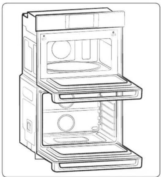
natural_image
Line drawing of an open multi-tiered appliance cabinet with internal compartments and ventilation slots (no text or symbols)- The overall design and/or accessories may differ with the model.
Installer
• To promote safety and minimize problems, read this manual thoroughly before starting the installation. Leave this manual with the user.
- Write the appliance's model/serial numbers in this manual for service/maintenance reference.
User
- Keep this manual for personal reference and for that of inspectors, service personnel, etc.
Customer-assurance info
If You Need Help...
To resolve installation issues, contact your Dacor® dealer or Dacor Customer Assurance. Have the oven model/serial numbers ready when youcall.
Dacor Customer Assurance
Phone: (800)793-0093 x2813 (USA, Canada)
Hours of Operation: Mon – Fri, 5:00 a.m. to 5:00 p.m. Pacific Time
Website: www.dacor.com/customer-care/contact-us
All specifications are subject to change without notice. Dacor assumes no liability for such changes.
© 2017 Dacor. All rights reserved.
Important safety instructions
Related equipment safety
Remove all tape and packaging before using the oven. Dispose of packaging after removal so it is not a danger to children. Never modify the oven (e.g., do not remove panels, wire covers, or screws).
Transport
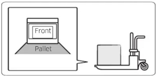
To avoid damaging the oven vent, support the oven bottom from either side when moving to the installation site. Leave the unit attached to the pallet until it is at the cabinet cutout, ready to be lifted into place.

WARNING
MOVING HAZARD
To avoid risk of severe personal injury; this appliance requires two or more people while handling and moving. Use of appliance moving devices is recommended.

DANGER
ELECTRICAL SHOCK HAZARD
To avoid risk of electrical shock, personal injury, or death; verify your appliance is grounded according to local codes or in their absence, with the National Electrical Code (NEC). ANSI/NFPA 70-latest edition.
Electrical Code Standards
If codes permit and a separate ground wire is used, a qualified electrical installer should confirm that the ground path and wire gauge comply with local codes. Check with a qualified electrical installer if you are unsure the oven is properly grounded. The oven must be connected to a grounded-metal, permanent wiring system. Ensure the electrical connection and wire size are adequate and comply with the National Electrical Code, ANSI/NFPA 70-latest edition or CSA Standards C22.1-94, Canadian Electrical Code, Part 1 and C22.2 No. O-M91-latest edition, and all local codes. A copy of these code standards can be obtained from:
National Fire Protection Association 1
Batterymarch Park
Quincy, MA 02169-7471
CSA International
OR 8501 East Pleasant Valley Road
Cleveland, OH 44131-5575
WARNING
- Follow the information in this manual precisely to avoid fire or electrical shock that may cause property damage, personal injury, or death.
- Save this manual for the local electrical inspector's use.
- Ensure the oven is properly installed and grounded by a qualified technician.
- New branch-circuit installations (1996 NEC), mobile homes, RVs, or installations where local codes prohibit grounding through the neutral conductor require 4-wire branch-circuit connection.
- Improper connection of aluminum house wiring to copper leads is an electrical or fire risk. Use only connectors designed for joining copper to aluminum, and follow the manufacturer's recommended procedure closely.
- Mounting screws must be used to keep the oven from falling out of the cabinet and causing property damage and serious injury.
CAUTION
- Cabinets and wall coverings around the oven must withstand the oven's heat (up to 194 °F [90 °C]); otherwise, discoloration, delamination, or melting may occur.
- DO NOT remove the spacers on the oven's side walls. The spacers center the oven in the cutout to prevent excess heat buildup that may result in heat damage or fire.
IMPORTANT NOTE
The installer shall ensure proper installation. Product failure due to improper installation is NOT covered under warranty.
WARNING
DO NOT let anyone climb, sit, stand, or hang on the oven door. The door could break free, causing property damage and personal injury.
WARNING
Electricity must be off while the electrical connections are made to prevent severe personal injury or death.
IMPORTANT NOTE
- Observe all governing ordinances.
- Do not block oven vents (bottom-front of the oven) or leave combustible or heat-sensitive items in front of them.
Installation requirements
Prepare to install the oven
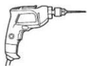
Tools you will need
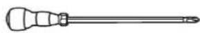
Phillips Screwdriver Drill
Included accessories
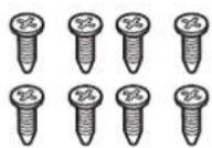
8 mounting screws (M4 L16) (6 screws for installation, 2 extras)
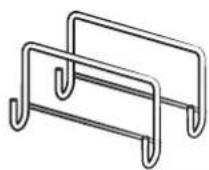
Install Handle
Needed Items
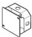
Junction Box Wire Nuts
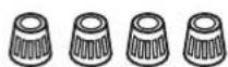
^3/_4 " Conduit Connector
Checklist
Review these items to verify proper installation:
- Before installation, read this manual thoroughly to familiarize yourself with the installation process.
- Verify the cabinet dimensions are correct and the required electrical connections are present.
- To lift the oven, hang the install handles on the oven's sides.
- Move the oven into place in front of the cabinet cutout, leaving the bottom packaging on the oven to avoid floor damage.
- Detach the oven from the pallet, and carefully team-lift the oven into the cutout.
- Ensure the electrical conduit reaches to the connection point properly.
- Slide the unit fully into place, while routing the electrical conduit correctly.
- With a Phillips screwdriver and supplied screws, anchor the oven to the cabinetry.
- Ensure that all installation procedures are followed as instructed.
- All product literature and accessories are included with the oven.
Location requirements
IMPORTANT: Observe all governing ordinances.
- Specified cabinet-opening dimensions are minimums and must be followed.
- Cabinet recess must enclose all but the oven face.
- Grounded electrical supply is required. (See Electrical connection.)
- Locate the junction box no more than 3" (7.6 cm) below the support platform. Drill a minimum 1" (2.5 cm) diameter hole in the right- or left-rear corner of the platform for easy power-plug access to the junction box.
- The support platform must be solid, level, flush with base of the cabinet cutout, and able to support 287 lb (130 kg).
• Install the oven at least 12" (30 cm) from other appliances.
IMPORTANT: Consult your builder or cabinet supplier to ensure the materials used will not discolor, delaminate, or be otherwise damaged. This oven complies with UL and CSA International requirements and with the maximum allowable wood-cabinet temperature of 194 °F (90 °C).
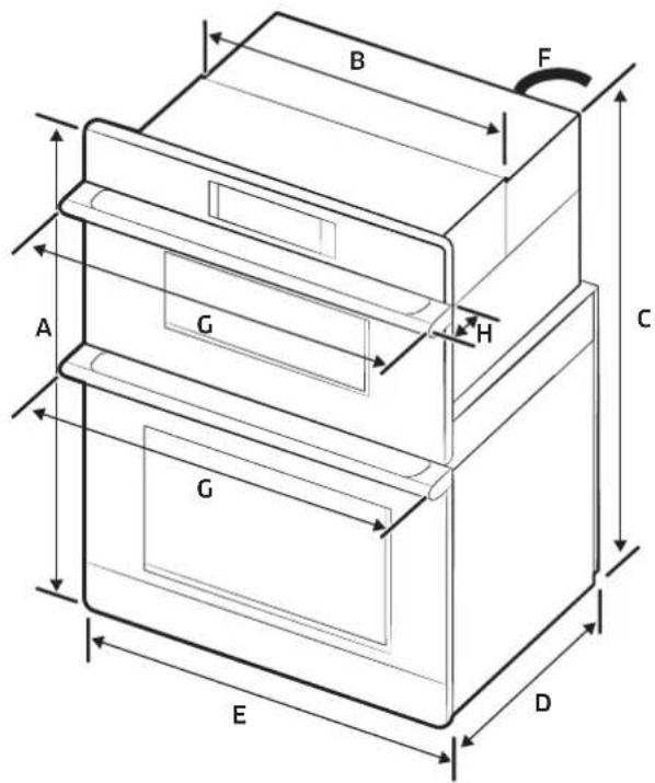
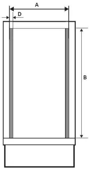
Product dimensions
| DIMENSION | ||
| A | 43 38 " (110.2 cm) | Overall height |
| B | 28 12 " (72.4 cm) | Recessed width |
| C | 42" (106.7 cm) | Recessed height |
| D | 23 18 " (58.7 cm) | Recessed depth |
| E | 29 34 " (75.6 cm) | Door Width |
| F | 67" (170 cm) | Conduit length |
| G | 30" (75.7 cm) | Overall width (Handle width) |
| H | 2 14 " (5.6 cm) | Handle Depth |
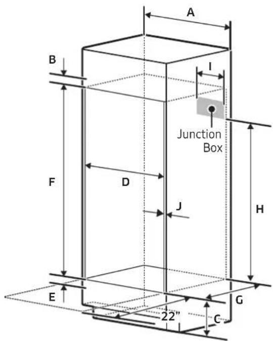
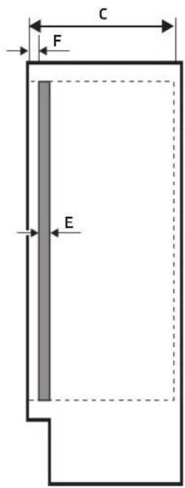
Cabinet dimensions
Standard Cabinet Installation
| DIMENSION | |
| A | 30" (76.2 cm) |
| B | Min 1 ^3 / _16 " (3.0 cm) |
| C | 12" (30.5 cm) |
| D | 28 ^5 / _8 " to 28 ^3 / _4 " (72.7 cm to 73.0 cm) |
| E | 1" to 1 ^1 / _4 " (2.5 cm to 3.2 cm) |
| F | 42 ^1 / _4 " (107.3 cm) |
| G | Min 23 ^1 / _2 " (Min 59.7 cm) |
| H | Min 30 ^1 / _2 " (Min 77.5 cm) |
| I | Max. 9 ^1 / _2 " (Max. 24.1 cm) Junction Box |
| J | Min. ^1 / _16 " (1.75 cm) Wooden cab't thickness |
At least 22" of space needed in front of oven so door can open fully
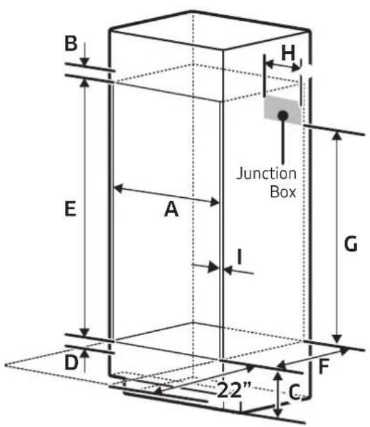
Installation requirements
Flush Cabinet Installation
| DIMENSION | |
| A | 30 ^3 / _16 " to 30 ^5 / _16 " (76.7 cm to 77.0 cm) |
| B | Min 1 ^3 / _16 " (3.0 cm) |
| C | 12" (30.5 cm) |
| D | 1" to 1 ^1 / _4 " (2.5 cm to 3.2 cm) |
| E | Min 43 ^11 / _16 " (110.9 cm) |
| F | Min 24 ^13 / _16 " (63.0 cm) |
| G | Min 30 ^1 / _2 " (Min 77.5 cm) |
| H | Max. 9 ^1 / _2 " (Max. 24.1 cm) Junction Box |
| I | Min. ^11 / _16 " (1.75 cm) Wooden cab't thickness |
At least 22" of space needed in front of oven so door can open fully
| CAB'T | DIMENSION | |
| A | 30 ^1/4 " (76.8 cm) | Width |
| B | 43 ^11/16 " (110.9 cm) | Height |
| C | 24 ^13/16 " (63.02 cm) | Depth |
| D | ^13/_16 " (2.06 cm) | Cleat Width |
| E | ^11/16 " (1.75 cm) | Cleat Depth |
| F | ^15/_16 " (3.3 cm) | Cleat Position |
Electrical Connection
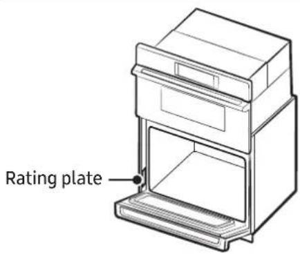
To properly install your oven, select an electrical connection type, and follow the manual's corresponding directions.
Connect the oven to the electrical voltage and frequency shown on the rating plate. (See left for location.)
A circuit breaker is recommended.
This chart will help you decide the minimum recommended dedicated circuit protection:
| KW Rating (240 V) KW Rating (208 V) | Recommended Circuit Size (Dedicated) | |
| ≤4.8 KW ≤4.1 KW 20 Amp | ||
| 4.9 KW - 7.5 KW 4.3 KW | 6.2 KW 30 Amp | |
| 7.3 KW - 9.6 KW 6.3 KW | 8.3 KW 40 Amp | |
| 9.7 KW - 12.0 KW 8.4 KW | - 10.4 KW 50 Amp | |
- Connect directly to the circuit-breaker box (or fused disconnect) via the flexible, armored or nonmetallic sheathed, copper cable with grounding wire. (See Electrical connection, pg. 9).
- Connect the oven's flexible conduit directly to the junction box.
- Fuse both sides of the line.
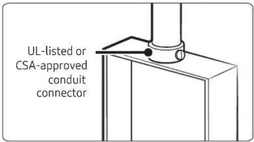
- Do not cut the conduit. The conduit length lets the oven be pulled out for service without disconnecting the conduit.
- A UL-listed or CSA-approved conduit connector must be provided.
- If the house has aluminum wiring: Connect a section of solid copper wire to the ends of the conduit leads, and connect the aluminum wiring to the added section of copper wire using special connectors/tools designed and UL-listed for joining copper to aluminum.
- Follow the connector manufacturer's recommended procedure. Aluminum/copper connection must comply with local codes and industry-accepted wiring practices.
For power requirement for model DOC30M977D, see this table.
| Model 240 VAC 208 VAC | |
| DOC30M977D 8.9 kW 6.7 kW |
Installation instructions
Prepare the oven
WARNING
Excessive Weight Hazard
To avoid personal injury and property damage, at least two people should move and install an oven.
- Avoid drilling or cutting into house wiring during installation.
- To avoid floor damage, set the oven on a cardboard pad. Do not lift by any part of the frame or handle.
- Remove the packaging and tape. Keep the packaging needed for installation.
- Remove the hardware package from the bag containing literature.
- Remove racks, etc. from the oven chamber.
- Move oven and cardboard close to the installation site.
Remove and reinstall the oven door
IMPORTANT: Lay a blanket or packing material on a flat, sturdy surface. Use two hands to remove the lower oven door, and lay it on the blanket/packing material.
The microwave-oven door is not removable.
Disconnect LED light wire harness
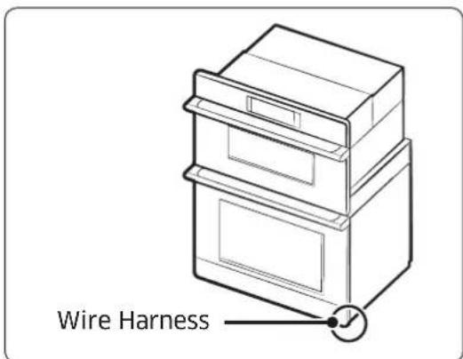
Locate the LED wire harness and disconnect it before removing the door.
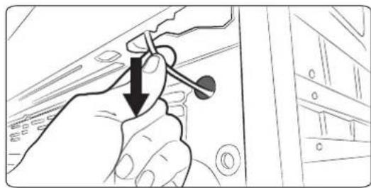
natural_image
Hand holding a tool with a downward arrow, pointing to a device panel (no text or symbols visible)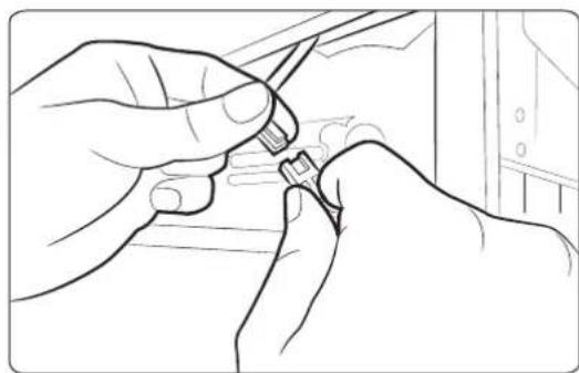
natural_image
Line drawing of hands using a tool to adjust or install a component (no text or symbols visible)Remove the lower oven door
natural_image
Technical line drawing of a door handle and lid assembly (no text or symbols)-
Carefully pull the wire to reveal the connector.
-
Disconnect the connector.

NOTE
When installing the unit, install the bottom trim before reinstalling the door. (See Install oven.)
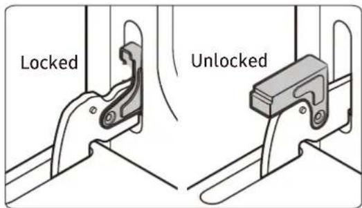
- Open the oven door.
-
At the bottom corners of the door, flip the hinge locks out-down to the unlocked position (see left). If the locks are not fully out, the door will not remove properly.
-
Partially close the door to engage the hinge locks, at which point the door will stop.
Installation instructions
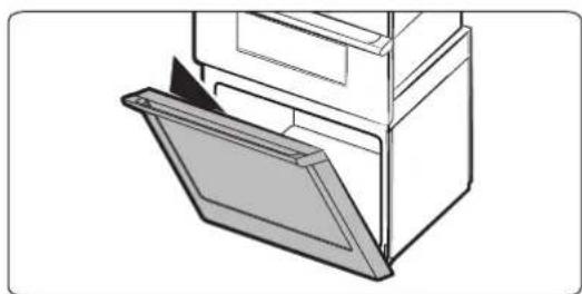
natural_image
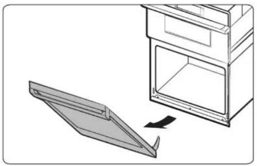
Diagram showing a door opening with an arrow indicating direction, no text or symbols present- Grasp both sides of the door below the handle; pull the door up and away from the oven. (Gently rock the door side to side as needed.)
- Set the door, handle down, on the covered surface you prepared.
- Go to Electric connection.
Reinstall the oven door

CAUTION
You may need help lifting the door to slide it into the hinge slots. Do not lift by the handle.
natural_image
Diagram showing a door opening with a magnified inset of the interior (no text or symbols)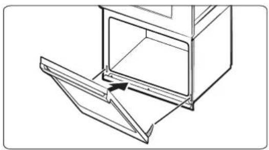
natural_image
Line drawing of a kitchen appliance with an open door and lid, showing internal structure and a directional arrow (no text or symbols)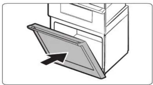
natural_image
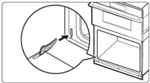
Diagram of a door opening with an arrow indicating direction (no text or symbols)- Grasp both sides of the door below the handle.
- At a 45^ angle, align the door hinges with the slots in the bottom corners of the oven chassis.
- Maintaining a 45^ angle, slowly insert the door. A slight drop indicates the door is engaged in the slots.
- Open the door all the way flat. If the door does not open a full 90^ , repeat Steps 1 – 3.
- Flip the hinge locks up-in to the locked position. (See Remove the lower oven door, pg. 12.)
- Close the oven door.
- If the gap between the oven doors is uneven, remove and reinstall the lower door. (See Remove the lower oven door, pg. 12.)
- Reconnect the LED wire harness at the bottom right of the door.
WARNING
Electrical Shock Hazard
- Disconnect power before servicing.
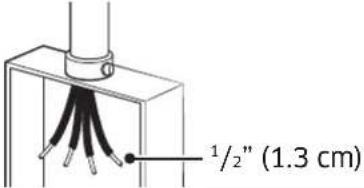
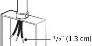
• Use 8-gauge, solid-copper wire. - Ground the oven.
This oven is manufactured with a neutral (white) power supply wire and a cabinet-connected ground (green or bare) wire twisted together.
- Di sconnect power.
- Feed the conduit through the opening in the cabinet.
- Remove the junction-box cover, and install a UL-listed or CSA-approved conduit connector to the junction box.
- Route the oven conduit to the junction box through the conduit connector.
- Tighten the conduit connector screws.
- See the chart below to complete installation for your electrical connection.
Electrical Connection Options Chart
| If your home has: Go to section: | |
 | 4-Wire Cable from Home Power Supply |
 | 3-Wire Cable from Home Power Supply |
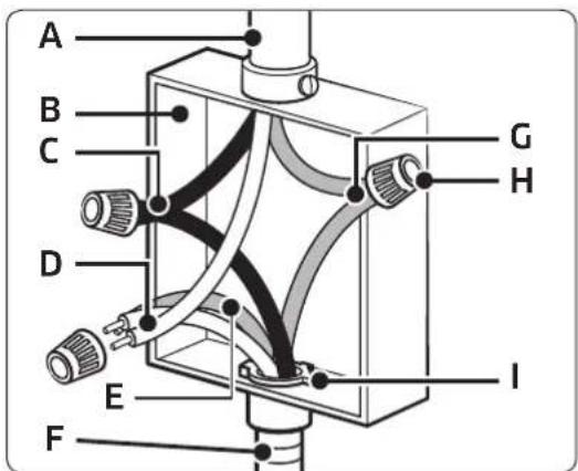
4-Wire Cable from Home Power Supply
IMPORTANT: Use in the US where codes do not allow grounding through neutral, New Branch circuit installations (1996 NEC), mobile homes and RVs, new construction, and in Canada.
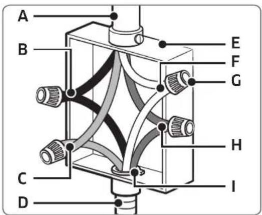
A) Cable from home power supply
B) Black wires (normally L1)
C) Red wires (normally L2)
D) 4-wire flexible conduit from oven
E) Junction box
F) White wires (normally N-neutral)
G) UL-listed wire connectors
H) Green wires (normally G-ground)
I) L-listed or CSA-approved conduit connector
-
Connect the 2 black wires (B) with a UL-listed wire connector.
-
Connect the 2 red wires (C) with a UL-listed wire connector.
-
Connect the 2 white wires (F) with a UL-listed wire connector.
-
Connect the green (bare) ground wire (H) from the oven cable to the green (bare) ground wire in the junction box with a UL-listed wire connector.
-
Install the junction-box cover.
3-Wire Cable from Home Power Supply (US Only)
IMPORTANT: Use where codes allow this connection.
A) Cable from home power supply
B) Junction box
C) Black wires (normally L1)
D) White wires (normally N-neutral)
E) Green wires (normally G-ground)
E) 4-wire flexible conduit from oven
F) Red wires (normally L2)
G) U- listed wire connectors
H) UElisted or CSA-approved conduit connector
Install the oven
natural_image
Diagram of a double oven with internal doors and ventilation ducts, showing airflow direction (no text or symbols)
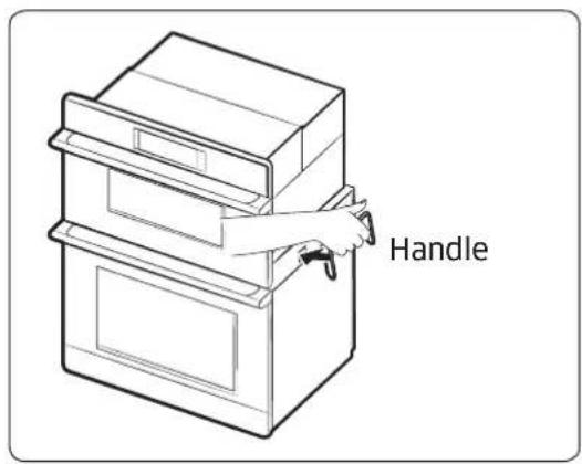
natural_image
Diagram showing a door handle mechanism with screwdriver and circular component, no text or symbols present- Using 2 or more people, lift the oven partially into the cabinet cutout. Use the handle as shown.
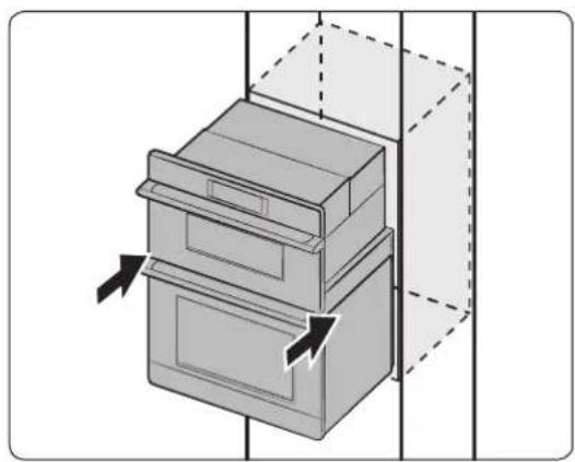
NOTE
- Carefully push on front oven frame.
-
Remove the install handles.
-
Pushing on the seal area of the front frame, slide the oven into the cabinet until the back of the front frame touches the cabinet front wall.
CAUTION
Do not push the upper oven (to prevent radio frequency leakage.)
- Center the oven in the cabinet cutout.
- Peel the tape from the front trims.
- Insert the provided screws through holes in the trim aligned with holes in lower oven frame, and anchor the oven to the cabinetry. (Do not overtighten the screws.)
Installation instructions
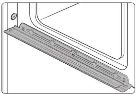
natural_image
Technical line drawing of a mechanical component with a bracket and mounting holes (no text or symbols)WARNING
When inserting the oven, take care not to deform or damage the barrier beneath.
Temp sensor and heater check
- After connecting power, verify the display function.
- Remove all accessories from the oven chamber.
- You cannot proceed with self-diagnosis if the oven chamber is hot or the door is open. (In either case Hot or door appears on the display.)
- To start self-diagnosis, touch-hold the hidden keys simultaneously for 5 seconds. (Self-diagnosis takes about 5 minutes.)
| Model DOC30M977D | |
| Control panel | |
| Hidden Key MICROWAVE + LOWER OVEN | |
- If there is no error, PASS appears on the display with an alert sound.
- If there is an error, a message appears on the display with an alert sound.
| Model | DOC30M977D | ||
| Error code Remark | |||
| Feature | Lower Broil H-4 | Lower Oven Only | |
| Lower Bake H-3 | |||
- If an error occurs or a message other than those listed above appears, contact a Dacor service center for service. (See pg. 4.)
Information codes
| Displayed code | Reason | Solution |
| C-d0 | Occurs if control key is short for 1 min. | Wipe/dry the control screen; turn off oven and try again; if issue persists, call a Dacor service center. |
| C-d1 | Occurs if door lock is mispositioned. | Touch PAUSE/OFF and OFF, and restart oven. If issue persists, disconnect power to oven for 30 seconds, and reconnect; if issue persists, call for service. |
| C-F0 | Communication between Main and Sub PBA was interrupted. | |
| C-F2 | Communication between Main and Touch was interrupted. | |
| C-20 | Oven sensor is open when oven operates. | |
| Oven sensor is short when oven operates. | ||
| C-21 | Occurs if the internal temperature rises abnormally high. | |
| C-23 | Temp probe sensor is short when oven operates. | |
| C-30 | PCB sensor is open when oven operates. | |
| PCB sensor is short when oven operates. | ||
| C-31 | PCB temperature is abnormally high. Call for service. | |
| C-70 | Steam sensor is open when oven operates. | Touch PAUSE/OFF and OFF, and restart oven; if issue persists, disconnect power to oven for 30 seconds, and reconnect; if issue persists, call for service. |
| Steam sensor is short when oven operates. | ||
| C-72 | Drain-system problems. | |
| C-A2 | Cooling motor is abnormally operated. Call for service. |
dacor®
natural_image
Line drawing of an open oven with a circular vent and lid, showing internal structure without any text or symbols.| DIMENSIONES | ||
| A 43 | ^3/_8" (110.2 cm) Altura total | |
| B 28 | ^1/_2" (72.4 cm) Ancho empotrado | |
| C 42" (106.7 cm) Altura empotrada | ||
| D 23 | ^1/_8" (58.7 cm) Profundidad empotrada | |
| E 29 | ^3/_4" (75.6 cm) Ancho de la puerta | |
| F 67" (170 cm) Longitud del conducto | ||
| G 30" (75.7 cm) Ancho total (ancho manija) | ||
| H 2 | ^1/_4" (5.6 cm) | Profundidad de la manija |
• National Fire Protection Association
1 Batterymarch Park
Quincy, MA 02169-7471
• CSA International
8501 East Pleasant Valley Road
Cleveland, OH 44131-5575
natural_image
Hand holding a tool with a black arrow pointing to a component, next to a server rack (no text or symbols visible)natural_image
Line drawing of hands using a tool to adjust or install a component (no text or symbols visible)- Desconéctelo.
NOTA
natural_image
Technical line drawing of a door handle and lid assembly (no text or symbols)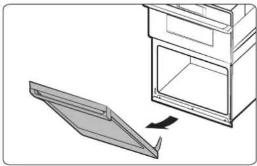
natural_image
Diagram showing a door opening with an open lid and a separate panel being inserted (no text or symbols)natural_image
Line drawing of a kitchen appliance with an open door and lid, showing internal structure and a directional arrow (no text or symbols)natural_image
Diagram of a door frame with an arrow indicating direction (no text or symbols)natural_image
Diagram of a double oven with internal doors and ventilation ducts, showing airflow direction (no text or symbols)
natural_image
Diagram showing a mechanical assembly with screwdrivers and a circular component, no text or symbols presentnatural_image
Technical line drawing of a mechanical bracket or panel assembly (no text or symbols)ADVERTENCIA
natural_image
Line drawing of an open oven with a circular vent and lid, showing internal structure without any text or symbols.Service client Dacor
• National Fire Protection Association
1 Batterymarch Park
Quincy, MA 02169-7471
• CSA International
8501 East Pleasant Valley Road
Cleveland, OH 44131-5575
natural_image
Hand holding a tool with a black arrow pointing downward, next to a server rack (no text or symbols visible)natural_image
Line drawing of hands using a tool to adjust or install a component (no text or symbols visible)natural_image
Technical line drawing of a door handle and lid assembly (no text or symbols)
natural_image
Diagram showing a door opening with an open lid and a folded panel, no text or symbols presentnatural_image
Line drawing of a door opening with an open lid and arrow indicating direction (no text or symbols)natural_image
Diagram of a cabinet or filing cabinet with an open door and arrow indicating direction (no text or symbols)natural_image
Technical line drawing of a mechanical assembly with labeled component A (no text or symbols beyond label)natural_image
Diagram of a double-door oven with directional arrows indicating airflow or movement (no text or symbols)
natural_image
Diagram showing a door handle mechanism with screwdriver and circular component, no text or symbols presentnatural_image
Technical line drawing of a mechanical bracket or panel assembly (no text or symbols)AVERTISSEMENT

- Installation Instructions
- Modernist Built-In Microwave Combination Oven
- DOC30M977D
- Contents
- Before you begin... 3
- Customer-assurance info 3
- Important safety instructions 4
- Installation requirements 5
- Installation instructions 11
- Troubleshooting 19
- Before you begin...
- Important
- Installer
- User
- Customer-assurance info
- If You Need Help...
- Dacor Customer Assurance
- Important safety instructions
- Related equipment safety
- Transport
- WARNING
- MOVING HAZARD
- DANGER
- ELECTRICAL SHOCK HAZARD
- Electrical Code Standards
- CAUTION
- IMPORTANT NOTE
- Installation requirements
- Prepare to install the oven
- Tools you will need
- Included accessories
- Needed Items
- Checklist
- Location requirements
- Product dimensions
- Cabinet dimensions
- Electrical Connection
- Prepare the oven
- Excessive Weight Hazard
- Remove and reinstall the oven door
- Disconnect LED light wire harness
- NOTE
- Reinstall the oven door
- Electrical Connection Options Chart
- 4-Wire Cable from Home Power Supply
- 3-Wire Cable from Home Power Supply (US Only)
- Install the oven
- Temp sensor and heater check
- dacor®
- NOTA
- ADVERTENCIA
- Service client Dacor
- AVERTISSEMENT
Brand : Dacor
Model : Modernist DOC30M977DS
Category : Microwave Oven