10029708 - Air Conditioning Klarstein - Free user manual and instructions
Find the device manual for free 10029708 Klarstein in PDF.


| Product type | Split air conditioner (indoor unit) |
| Brand | Klarstein |
| Model | 10029708 |
| Dimensions (W x H x D) | 770 x 283 x 201 mm |
| Net weight | 8 kg |
| Power supply | 220-240 V~, 50 Hz |
| Cooling capacity | 2600 W |
| Heating capacity | 2800 W |
| Dehumidification capacity | 0.8 l/h |
| Airflow | 280 - 600 m³/h |
| Sound pressure level | 24 - 41 dB(A) |
| Refrigerant | R410A |
| Refrigerant quantity | 0.7 kg |
| Main functions | Auto, Cool, Dry, Fan, Heat, Turbo, Sleep, Health/Economy, Oscillation, Timer |
| Fan speeds | Auto, Low, Medium, High |
| Adjustable temperature range | 16 - 30 °C |
| Remote control | Yes, with LCD display, LR03 batteries (not included) |
| Filter maintenance | Clean every 3 months (more often in dusty environment) |
| Safety | Do not use extension cord, unplug before cleaning, do not repair yourself |
| Installation | By a qualified professional; provide a dedicated circuit breaker |
Frequently Asked Questions - 10029708 Klarstein
User questions about 10029708 Klarstein
0 question about this device. Answer the ones you know or ask your own.
Ask a new question about this device
Download the instructions for your Air Conditioning in PDF format for free! Find your manual 10029708 - Klarstein and take your electronic device back in hand. On this page are published all the documents necessary for the use of your device. 10029708 by Klarstein.
USER MANUAL 10029708 Klarstein
Congratulations on purchasing this equipment. Please read this manual carefully and take care of the following hints on installation and use to avoid technical damages. Any failure caused by ignoring the items and cautions mentioned in the operation and installation instructions are not covered by our warranty and any liability.
Contents
Technical Data 30
Safety Instructions. 31
Product Description 33
Remote Control. 34
Cleaning and Maintenance. 40
Troubleshooting 41
Installation Instructions (for the Installer only) 45
Disposal Considerations 57
Declaration of Conformity 57
Technical Data
| Item number 10029708 10029709 | ||
| Rated voltage and frequency 220-240 V~, 50 Hz 220-240 V~, 50 Hz | ||
| Measurements (B x H x T) 770 x 283 x 201 mm 770 x 283 x 201 mm | ||
| Weight (net) 8 kg 9 kg | ||
| Cooling capacity 2600 W 3500 W | ||
| Heating capacity 2800 W 3800 W | ||
| Dehumidifying Volume 0.8 l/h 1.4 l/h | ||
| Air flow volume | 280 - 600 m³/h | 300 - 680 m³/h |
| Sound pressure level | 24 - 41 dB (A) | 25 - 42 dB (A) |
| Refrigerant Refrigerant charge | R 410A0.7 kg | R 410A0.85 kg |
Safety Instructions
Product safety
- This appliance can be used by children aged from 8 years and above and persons with reduced physical, sensory or mental capabilities or lack of experience and knowledge if they have been given supervision or instruction concerning use of the appliance in a safe way and understand the hazards involved.
- Do not connect air conditioner to multi-purpose socket. Otherwise, it may cause fire hazard.
- Do disconnect power supply when cleaning air conditioner. Otherwise, it may cause electric shock.
- If the supply cord is damaged, it must be replaced by the manufacturer, its service agent or similarly qualified persons in order to avoid a hazard.
- Do not wash the air conditioner with water to avoid electric shock.
- Do not spray water on indoor unit. It may cause electric shock or malfunction.
After removing the filter, do not touch fins to avoid injury. Do not use fire or hair dryer to dry the filter to avoid deformation or fire hazard. - Maintenance must be performed by qualified professionals. Otherwise, it may cause personal injury or damage.
-
When below phenomenon occurs, please turn off air conditioner and disconnect power immediately, and then contact the dealer or qualified professionals for service.
-
Power cord is overheating or damaged.
- There's abnormal sound during operation.
- Circuit break trips off frequently.
Air conditioner gives off burning smell. -
Indoor unit is leaking.
-
If the air conditioner operates under abnormal conditions, it may cause malfunction, electric shock or fire hazard.
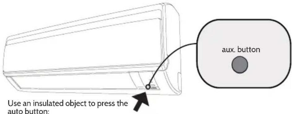
- When turning on or turning off the unit by emergency operation switch, please press this switch with an insulating object other than metal.
- Do not step on top panel of outdoor unit, or put heavy objects. It may cause damage or personal injury.
- Do not repair air conditioner by yourself. It may cause electric shock or damage. Please contact dealer when you need to repair air conditioner.
- Installation must be performed by qualified professionals. Otherwise, it may cause personal injury or damage.
Specific safety instructions
- Do not overcool the room temperature. This is not good for health and wastes electricity.
- Keep blind or curtains closed. Do not let sunshine enter the room directly when the air condition is in operation.
- Keep the room temperature uniform. Adjust the vertical and horizontal airflow direction to ensure uniform temperature in the room. Air can't be discharged to the direction of air-in.
- Make sure that the doors and windows are tightly closed. Avoid opening doors and windows as much as possible to keep air conditioning in the room.
- Clean the air filter regularly. Blockages in the air filter reduce dehumidifying effects. Clean the air filter at least once every two weeks.
- Ventilate the room occasionally. Since windows are kept closed, it is a good idea to open them and ventilate the room now and then. When starting the unit, curtains or windows should be closed to prevent the heat/cool leakage.
- Wait about three minutes and operation will begin.
Product Description
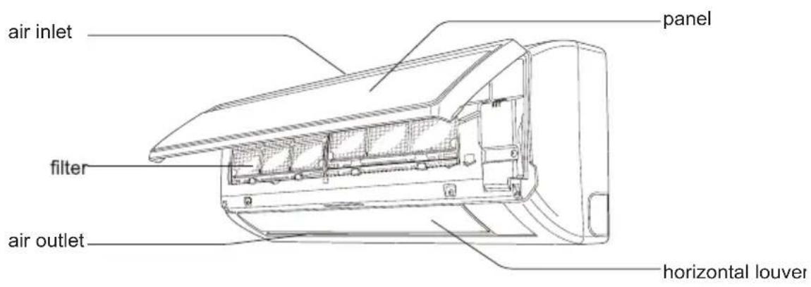
Innengerat
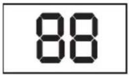
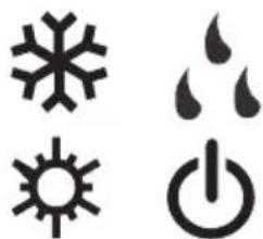
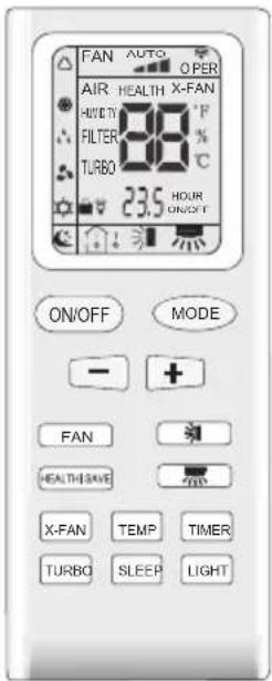
Display Remote Control
Remote Control
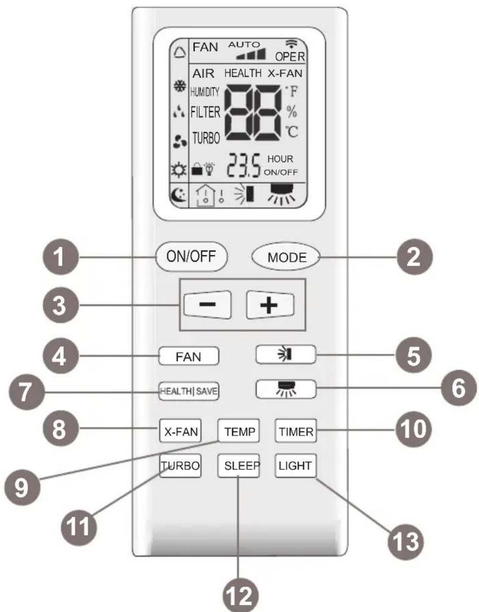
1 ON/OFF button
2 MODE button
3 +/- button
4 FAN button
5 Swing button (up/down)
6 Swing button (left/right)
7 HEALTH SAVE button
8 X-FAN button
9 TEMP button
10 TIMER button
11 TURBO button
12 SLEEP button
13 LIGHT button
Display on the remote control
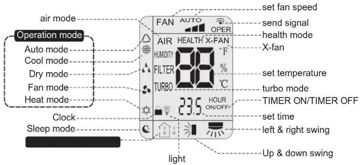
Notes:
- Press this button can turn on or turn off the air conditioner.
- After turning on the unit, operation indicator on indoor unit is ON (green indicator. Color may be different for different models) and indoor unit gives out a sound.

2 MODE button
-
Press this button can select your required operation mode.
-
AUTO: After selecting auto mode, air conditioner will operate automatically according to ambient temperature. Set temperature can't be adjusted and also can't be displayed. Press "FAN" button can adjust fan speed. Press and button can adjust swing angle.
- COOL: After selecting cool mode, air conditioner operates under cool mode. Cool indicator on indoor unit is ON. You can press "+" or "-" button to adjust set temperature. Press "FAN" button can adjust fan speed. Press button and button can adjust swing angle.
- DRY: After selecting dry mode, air conditioner operates under dry mode at low speed. Dry indicator on indoor unit is ON. Under dry mode, fan speed can't be adjusted. Press and button to adjust swing angle.
- FAN: After selecting fan mode, air conditioner operates only under fan mode, All mode indicators on indoor unit is OFF. Operation indicator is on. Press "FAN" button can adjust fan speed. Press and button to adjust swing angle.
- HEAT: After selecting heat mode, air conditioner operates under heat mode. Heat indicator on indoor unit is ON. You can press "+" and "-" button to adjust set temperature. Press "FAN" button to adjust fan speed. Press and button to adjust swing angle. (Cooling only unit can't receive the signal for heating mode.)
Note: For preventing cold wind, after starting up heating mode, indoor fan will blow fan after delay- ing 1-5min. (Details time is decided by indoor ambient temperature) Temperature setting range on remote controller: 16^ C - 30^ C . Fan speed setting range: auto, low speed, medium speed and high speed.
3 + and - button:
- Setting the temperature: After each pressing of "+" or "-" button, it can increase or decrease set temperature 1°C. Hold "+" or "-" button, 2s later, set temperature on remote controller will change quickly. After reaching to your required time, loosen the button. Temperature indicator on indoor unit will also change accordingly. (Temperature can't be adjusted under auto mode).
- Timer on/off or Clock setting: Press + + or - - button to adjust time. (Refer to TIMER button for details)
4 FAN
Pressing this button can set fan speed circularly as: auto (AUTO), low, medium, high

Note: Under AUTO Speed, IDU fan motor will adjust the fan speed (high, medium or low speed) according to ambient temperature.
5 Swing buttons
Press this button can select up&down swing. Swing angle can be selected in sequence as below.
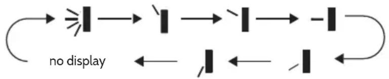
When selecting - conditioner will stop at that position as shown by the icon to swing.
Press this button can select up&down swing. Swing angle can be selected in sequence as below.

When selecting with remote controller, it is auto swing. Horizontal louver of air conditioner will swing left&right automatically at the maximum angle.
When selecting with the remote control, the position swing is fixed. Horizontal couver of air conditioner will stop at that position as shown by the icon to swing.
When selecting the swing circulates. Horizontal louvers of air conditioner will swing circularly according to the angle as shown by the icon.
7 HEALTH/SAVE
Health function: After pressing HEALTH button, remote controller will switch circularly as below HEALTH AIR AIRHEALTH "no display"
- When selecting the one of the functions above the corresponding function will be startet..
SAVE function: Under cool mode, press SAVE button and the unit will operate under SAVE mode. Dual-8nixie tube on remote controller displays „SE". Air conditioner will operate at auto speed. Set temperature can't be adjusted. Press SAVE button again to exit SAVE mode. Air conditioner turn back to original set speed and set temperature.
This function is applicable to partial of models.
8 After pressing this button under cooling or dry mode, remote controller displays the character of „X-FAN“ and X-FAN function is started up. Press this button again to cancel X-FAN function. The character of „X-FAN“ will disappear.
After starting up X-FAN function, when turning off the unit, indoor fan will continue to operate for a
while at low speed to dry the residual water inside the indoor unit.
9 TEMP button
Press this button allows you to the see indoor set temperature, indoor ambient temperature or outdoor ambient temperature on indoor unit's display. Temperature is set circularly by remote controller as below.
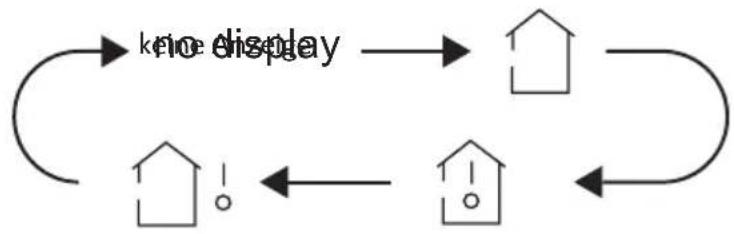
- When selecting by remote control or no display, the temperature indicator on indoor unit displays set temperature.
- When selecting by remote control, the temperature indicator on indoor unit displays indoor ambient temperature.
- When selecting by remote control, the temperature indicator on indoor unit displays outdoor ambient temperature.
Notes: Outdoor ambient temperature display may can't be selected for some models. When indoor unit receives signal, it displays indoor ambient temperature. Only for the model whose indoor unit have dual-8 display.
10 TIMER
- Timer off: At ON status, press this button once can set TIMER OFF. The character of HOUR and OFF will flash. Press + or - button within 5s to adjust the time of TIMER ON. After each pressing of "+" or "-" button, time will increase or decrease half an hour. When holding "+" or "-" button, 2s later, the time will change quickly until to reach your required time. After that, press the TIMER button to confirm it. The character of HOUR and FLASH will not flash any more. Cancel TIMER OFF: Press "TIMER" button again under TIMER OFF status.
- Timer on: At OFF status, press this button once can set TIMER ON. Please refer to TIMER off for detailed operation.
Time setting range: 0.5-24 hours. Time interval between two operations can't exceed 5s. Otherwise, remote controller will exit the setting status automatically.
11 TURBO
When pressing this button under cooling or heating mode, air conditioner will enter into quick cooling or quick heating mode. The character of „TURBO“ is displayed on remote controller. Press this button again to exit turbo function and the character of „TURBO“ will be disappeared on remote control.
12 SLEEP
Press this button under cooling, heating mode can start up sleep function. The icon will be displayed on remote controller. Press this button again to cancel sleep function. The icon on remote control will not be displayed any more.
13 LIGHT
Press this button can turn off the light for indoor unit's display: The icon on remote control will disappear. Press this button again to turn on the light for indoor unit's display. The icon on remote control will be displayed.
Key combinations
Child lock function
Pressing "+" and "-" buttons simultaneously can turn on or turn off the child lock function. When the child lock function is started up, the icon will be displayed on the remote control. If you operate the remote control the icon will flash three times while the remote will not send any signal.
Operation
- After putting through the power, press ON/OFF button on remote control to turn on the air conditioner.
- Press the "MODE" button to select your required mode: AUTO, COOL, DRY, FAN, HEAT.
- Press the "+" or "-" button to set your required temperature. (Temperature can't be adjusted under auto mode).
- Press the "FAN" button to set your required fan speed: auto, low, medium and high speed.
- Press the and buttons to select fan blowing angle.
signal sender battery
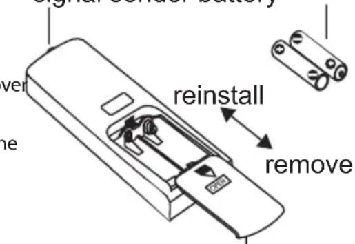
Replacement of batteries in remote control
- Press the back side of remote control and then push out the cove of the battery box along the arrow direction.
- Replace two 7# (AAA 1.5V) dry batteries, and make sure the position of ^ + ^ polar and ^ - ^ polar are correct.
- Reinstall the cover of battery box.
Note:
Cover of battery box
- During operation, point the remote control signal sender at the receiving window on indoor unit.
- The distance between signal sender and receiving window should be no more than 8m , and there should be no obstacles between them.
- Signal may be interfered easily in the room where there is a fluorescent lamp or wireless telephone; remote control should be close to indoor unit during operation.
Emergency operation
If remote controller is lost or damaged, please use auxiliary button to turn on or turn off the air conditioner. The operation in details are as below: conditioner. When the air conditioner is turned on, it will operate under auto mode.
Cleaning and Maintenance
Clean surface of indoor unit
- The filter could be cleaned every three months. If there is much dust in the operation environment, the cleaning frequency can be increased.
After removing the filter, do not touch the fins to avoid injury. - Do not use fire or hair dryers to dry the filter to avoid deformation or fire hazard.
Checking before use season
- Check whether air inlets and air outlets are blocked.
- Check whether air switch, plug and socket are in good condition.
- Check whether filter is clean.
- Check whether drainage pipe is damaged.
Checking after use-season
- Disconnect power supply.
- Clean filter and the panel of the indoor unit.
Open panel
Pull out the panel to a certain angle as shown in the fig.

3
Clean filter
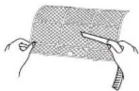
- Use dust catcher or water to clean the filter.
- When the filter is very dirty, use the water (below 45^ ) to clean it, and then put it in a shady and cool place to dry.
2
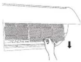
Remove filter
Remove the filter as indicated in the fig.
4
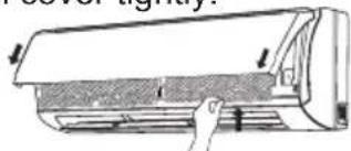
Install filter
Install the filter and then close the panel cover tightly.
Troubleshooting
| Phenomenon Check items | Solution | |
| Indoor unit cannot receive remote control signal or remote control has no action. | Whether it's interfered severely (such as static electricity, stable voltage). | Pull out the plug. Reinsert the plug after about 3min, and then turn on the unit again. |
| Whether remote controller is within the signal receiving range. | Signal receiving range is 8m. | |
| Whether there are obstacles. Remove obstacles. | ||
| Whether remote controller is pointing at the receiving window. | Select proper angle and point the remote controller at the receiving window on indoor unit. | |
| Is sensitivity of remote control low; fuzzy display and no display? | Check the batteries. If the power of batteries is too low, please replace them. | |
| No display when operating remote control. | Check whether remote control appears to be damaged. If yes, replace it. | |
| Indoor unit cannot receive remote control signal or remote control has no action. | Fluorescent lamp in room? | Take the remote control close to indoor unit. Turn off the fluorescent lamp and then try it again. |
| Air conditioner does not operate | Power failure? Wait until power recovery. | |
| Is plug loose? Reinsert the plug. | ||
| Air switch trips off or fuse is Wiring has malfunction | Ask a professional to replace air switch or fuse. | |
| Unit has restarted immediately after stopping operation. | Wait for 3min, and then turn on the unit again. | |
| Whether the function setting for remote control is correct. | Reset the function. | |
| Mist is emitted from indoor unit's air outlet. | Indoor temperature and humidity is high? | Because indoor air is cooled rapidly. After a while, indoor temperature and humidity will be decrease and mist will disappear. |
| No air emitted from indoor unit. | Is the air inlet or air outlet of indoor unit is blocked? | Eliminate obstacles. |
| Has the indoor temperature reached the set temperature (in heating mode)? | After reaching to set temperature, indoor unit will stop blowing out air. | |
| Has the heating mode been turned on just now? | In order to prevent blowing out cold air, indoor unit will be started after delaying for several minutes, which is a normal phenomenon. | |
| Set temperature cannot be adjusted. | Is the unit is operating under auto mode? | Temperature can't be adjusted under auto mode. Please switch the operation mode if you need to adjust the temperature. |
| Your required temperature exceeds the set temperature range? | Set temperature range: 16 °C~30 °C. | |
| Cooling (heating) effect is not good | Is the voltage is too low? | Wait until the voltage resumes normal. |
| Is the filter dirty? Clean the filter. | ||
| Set temperature is in proper range? | Adjust temperature to proper range. | |
| Door and window are open? Close | door and window. | |
| Odours are emitted. | Whether there is odour source, such as furniture and cigarette, etc. | Eliminate the odour source. Clean the filter. |
| Air conditioner does suddenly not operate normally. | Whether there is interference, such as thunder, wireless devices, etc. | Disconnect power, put back power, and then turn on the unit again. |
| Outdoor unit has vapour. | Is the heating mode is turned on? | During defrosting under heating mode, it may generate vapour, which is a normal phenomenon. |
| “Water flowing” noise. | Air conditioner is turned on or turned off just now? | The noise is the sound of refriger-ant flowing inside the unit, which is a normal phenomenon. |
| Cracking noise. | Air conditioner is turned on or turned off just now? | This is the sound of friction caused by expansion and/or contraction of panel or other parts due to the change of temperature. |
Error codes
When air conditioner status is abnormal, temperature indicator on indoor unit will blink to display corresponding error code. Please refer to below list for identification of error code.
| Error code Troubleshooting | |
| Heating indicator ON 10s OFF 0.5s | Means defrosting status. It's the normal phenomenon. |
| C5: Malfunction of connector jumper | Check if the connector jumper contacts properly. If the PCB is to be replaced, please take off the old for the new PCB. |
| F1:Malfunction of indoor ambient temperature sensor | Check if indoor room temperature sensor is connected properly. |
| F2:Malfunction of evaporator temperature sensor | Check if the evaporator temperature is connected properly. |
| H6:Indoor fan block Check | if the terminal of the indoor motor is connected properly. Replace the fan motor or the indoor board if disabled. |
| E5 Please contact qualified | professionals for service. |
| E8 Please contact qualified | professionals for service. |
| U8 Please contact qualified | professionals for service. |
| Defrosting or oil return mode | It is normal. The indicating lamp in heat mode will wink 0.5s and light 10s. |
Note: If there're other error codes, please contact qualified professionals for service.
When below phenomenon occurs, please turn off air conditioner and discon-nect power immediately, and then contact the dealer or qualified professionals for service:
Power cord is overheating or damaged.
There's abnormal sound during operation.
Air switch trips off frequently.
Air conditioner gives off burning smell.
- Indoor unit is leaking
-
Do not repair or refit the air conditioner by yourself.
-
If the air conditioner operates under abnormal conditions, it may cause malf-unction, electric shock or fire hazard.
Installation Instructions (for the Installer only)
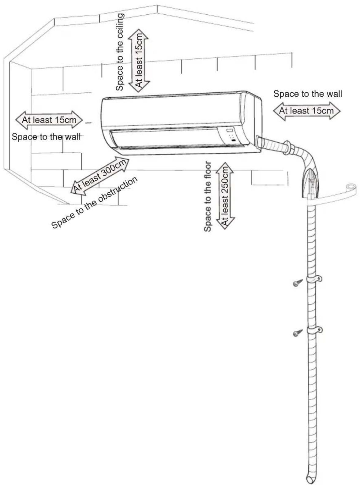
Installion dimension diagram
Tools for installation
- Level metre
- Screw driver
- Impact drill
- Drill head
Pipe expander - Torque wrench
-
Open-end wrench
Pipe cutter -
Leakage detector
Vacuum pump
Pressure meter
Universal meter - Inner hexagon spanner
- Measuring tape
Note: Please contact the local agent for installation. Do not use unqualified power cord.
Selection of installation location
Basic requirements
Installing the unit in the following places may cause malfunction. If it is unavoidable, please consult the local dealer.
- a place near strong heat sources vapours, flammable or explosive gas, or volatile objects spread in the air
- a place with high-frequency devices (such as welding machine, medical equipment).
- a place near a coastal area.
- places with oil or fumes in the air.
- places with sulphurated gas.
- other places with special circumstances.
- Please try your best to keep way from fluorescent lamp.
Indoor unit
- Avoid installing the indoor unit in a place where generated or leaked inflammable gas will stay.
- Avoid installing the indoor unit in a moist place or in a place where oil may be splashed on the unit.
- Select a location
where outlet air may reach each corner of the room.
where connection pipe can be led to outdoor conveniently.
where air inlet and outlet won't be blocked.
with least affection of outdoor air.
- Retain sufficient space for maintenance and installation.
-
Ensure the installation meets the requirement of installation dimension diagram.
-
Do not use the unit in the immediate surroundings of a laundry a bath a shower or a swimming pool.
Safety precautions
- Must follow the electric safety regulations when installing the unit.
- If the supply cord is damaged, it must be replaced by the manufacturer or its service agent or a similarly qualified person in order to avoid a hazard.
- According to the local safety regulations, use qualified power supply circuit and air switch.
- An air switch having a contact separation of at least 3mm in all poles should be fixed in fixed wiring.
- The appliance shall be installed in accordance with national wiring regulation.
- The air switch must have the functions of magnetic tripping and heat tripping in order to prevent short circuit or overload. Please install the air switch with suitable capacity according to the sheet below.
- Make sure the power supply matches with the requirement of air conditioner. Unstable power supply or incorrect wiring may result in electric shock, fire hazard or malfunction. Please install proper power supply cables before using the air conditioner.
- Properly connect the live wire, neutral wire and grounding wire of power socket.
- Be sure to cut off the power supply before proceeding any work related to electric safety.
- Do not put through the power before finishing installation.
Grounding requirement
- The air conditioner is first class electric appliance. It must be properly grounded with specialized grounding device by a professional. Please make sure it is always grounded effectively, otherwise it may cause electric shock.
- The yellow-green wire in air conditioner is grounding wire, which can't be used for other purposes.
- The grounding resistance should comply with national electric safety regulations.
Installation of indoor unit
Step 1: recommend the installation location to the client and then confirm it with the client.
Step 2: opening pipe hole
- Choose the position of piping hole according to the direction of outlet pipe.
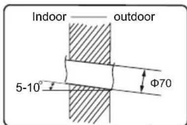
- Open a piping hole with the diameter of 70~mm on the selected outlet pipe position. In order to drain smoothly, slant the piping hole on the wall slightly downward to the outdoor side with the gradient of 5 - 10^ .
- Fix the wall-mounting frame on the wall with tapping screws (ST4.2X25TA) and then check if the frame is firmly installed by pulling the frame. If the plastic expansion particle is loose, please drill another fixing hole nearby.
Step 3: open piping hole
- Choose the position of piping hole according to the direction of outlet pipe. The
- position of piping hole should be a little lower than the wall-mounted frame, shown as below
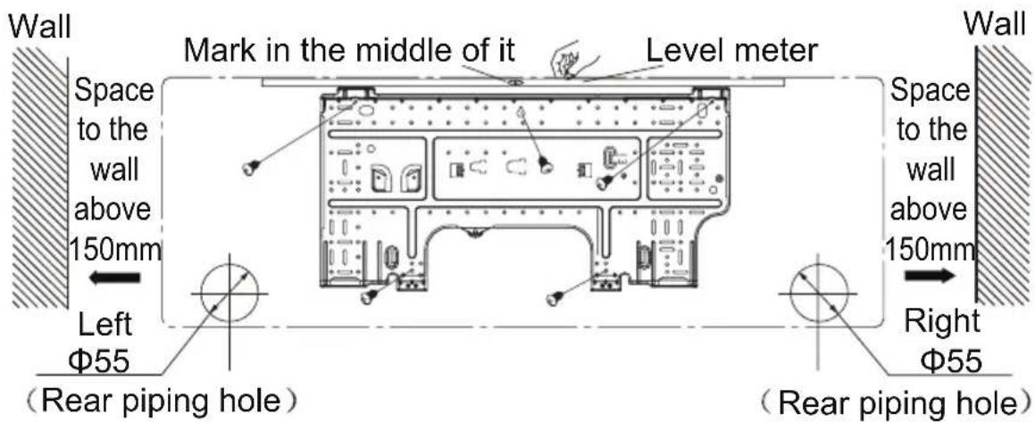
- Open a piping hole with the diameter of 55 / 70 on the selected outlet pipeposition. In order to drain smoothly, slant the piping hole on the wall slightly downward to the outdoor side with the gradient of 5 - 10^
Pay attention to dust prevention and take relevant safety measures when opening the hole.
The plastic expansion particles are not provided and should be bought locally.
Step 4:outlet pipe
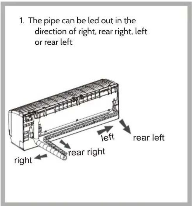
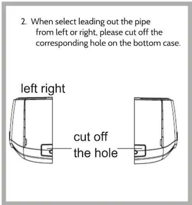
Step 5: connect the pipe of indoor unit
- Aim the pipe joint at the corresponding bellmouth.
- Pre-tighten the union nut with hand.
- Adjust the torque force by referring to the following sheet. Place the opened wrench on the pipe joint and place the torque wrench on the union nut. Tighten the union nut with torque wrench.
| Tightening torque (N·m) | |
| Φ 6.35 (1/4") | 15.7 (1.6kg.m) |
| Φ 9.52 (3/8") | 29.4 (3.0kg.m) |
| Φ 12.70 (1/2") | 49.0 (5.0kg.m) |
| Φ 15.88 (5/8") | 73.6 (7.5kg.m) |
- Wrap the indoor pipe and joint of connection pipe with insulating pipe, and then wrap it with tape.

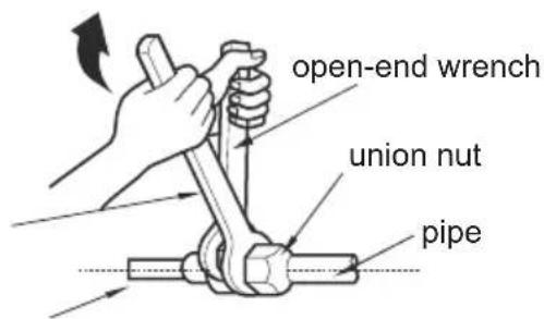
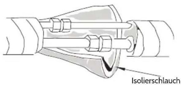
Step 6: install drain hose
-
Connect the drain hose to the outlet pipe of indoor unit.
-
Bind the joint with tape.
-
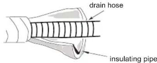
Add insulating pipe in the indoor drain hose in order to prevent condensation.
- The plastic expansion particles are not provided.

Step 7: connect wire of indoor unit
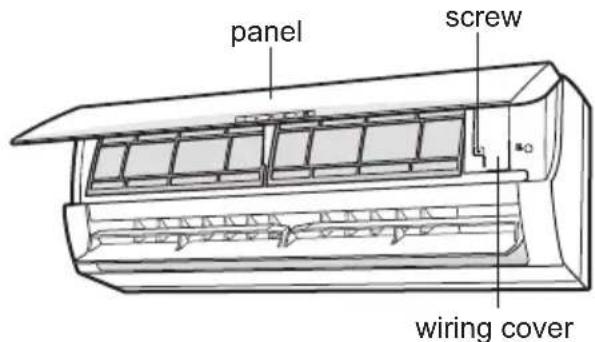
- Open the panel, remove the screw on the wiring cover and then take down the cover.
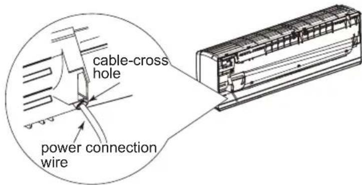
- Make the power connection wire go through the cable-cross hole at the back of indoor unit and then pull it out from the front side..
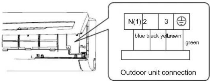
- Remove the wire clip; connect the power connection wire to the wiring terminal according to the color; tighten the screw and then fix the power connection wire with wire clip.
- Put wiring cover back and then tighten the screw.
- Close the panel.
Notes
- All wires of indoor unit and outdoor unit should be connected by a professional. for a new one. Avoid extending the wire by yourself. installation.
- For the air conditioner without plug, an circuit break must be installed in the line.
- The air switch should be all-pole parting and the contact parting distance should be more than 3mm .
Step 8: bind up pipe
- Bind up the connection pipe, power cord and drain hose with the band.
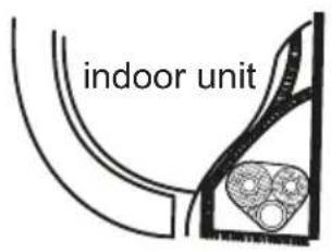
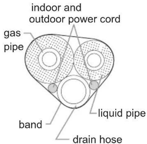
- Reserve a certain length of drain hose and power cord for installation when binding them. When binding to a certain degree, separate the indoor power and then separate the drain hose.
- Bind them evenly.
- The liquid pipe and gas pipe should be bound separately at the end.
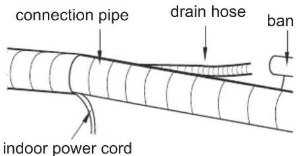
Notes:
- The power cord and control wire can't be crossed or winding.
- The drain hose should be bound at the bottom..
Step 9: hang the indoor unit
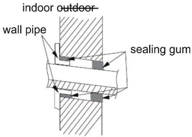
- Put the bound pipes in the wall pipe and then make them pass trough the wall hole.
- Hang the indoor unit on the wall-mounting frame.
- Stuff the gap between pipes and wall hole with sealing gum.
- Fix the wall pipe.
- Check if the indoor unit is installed firmly and closed to the wall
Do not bend the drain hose too excessively in order to prevent blocking.
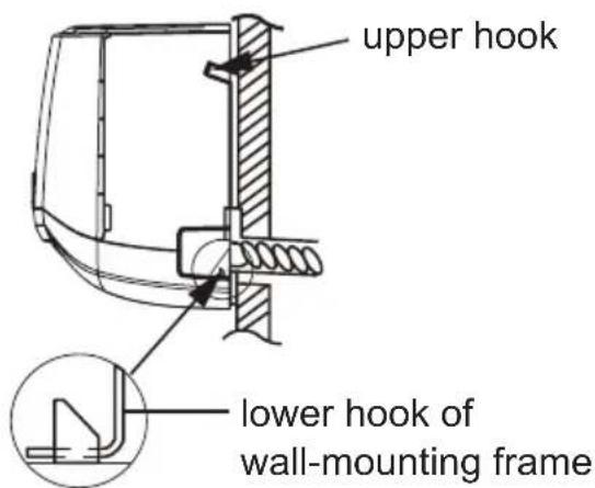
Check after installation
| Items to be checked Possible malfunction | |
| Has the unit been installed firmly? The unit may drop, shake or emit noise. | |
| Have you done the refrigerant leakage test? It may cause insufficient cooling (heating) capacity. | |
| Is heat insulation of pipeline sufficient? It may cause condensation and water dripping. | |
| Is water drained well? It may cause condensation and water dripping. | |
| Is the voltage of power supply according to the voltage marked on the nameplate? | It may cause malfunction or damage the parts. |
| Is electric wiring and pipeline installed correctly? It may cause malfunction or damage the parts. | |
| Is the unit grounded securely? It may cause electric leakage | |
| Does the power cord follow specification? It may cause malfunction or damage the parts. | |
| Is there any obstruction in air inlet and air outlet? It may cause insufficient cooling (heating). | |
| The dust and sundries caused during installation are removed? | It may cause malfunction or damage the parts. |
| The gas valve and liquid valve of connection pipe are open completely? | It may cause insufficient cooling (heating) capacity. |
Test operation
-
Preparation of test operation
-
The client approves the air conditioner installation.
-
Specify the important notes for air conditioner to the client.
-
Method of test operation
-
Put through the power, press ON/OFF button on the remote controller to start operation.
- Press MODE button to select AUTO, COOL, DRY, FAN and HEAT to check whether the operation is normal or not.
- If the ambient temperature is lower than 16^ , the air conditioner cannot start cooling.
Configuration of connection pipe
- Standard length of connection pipe: 5, 7.5, 8 m.
- Min. length of connection pipe is 3m
- Max. length of connection pipe and max. height difference.
| Cooling capacity M | Max length of pipe | Max. height difference |
| 5000 Btu/h (1465 W) | 15 m 5 | |
| 7000 Btu/h (2051 W) | 15 m 5 | |
| 9000 Btu/h (2637 W) | 15 m 5 | |
| 12000 Btu/h (3516 W) | 20 m 10 | |
| 180 Btu/h (5274 W) | 25 m 10 |
| Cooling capacity M | Max length of pipe | Max. height difference |
| Btu/h (1465 W) | 15 m 5 | |
| 7000 Btu/h (2051 W) | 15 m 5 | |
| 9000 Btu/h (2637 W) | 15 m 5 | |
| 12000 Btu/h (3516 W) | 20 m 10 | |
| 180 Btu/h (5274 W) | 25 m 10 |
- The additional refrigerant oil and refrigerant charging required after prolonging connection pipe.
After the length of connection pipe is prolonged for 10m at the basis of standard length, you should add 5 ml of refrigerant oil for each additional 5 m of connection pipe.
- The calculation method of additional refrigerant charging amount (on the basis of liquid pipe):
Additional refrigerant charging amount = prolonged length of liquid pipe × additional refrigerant charging amount per meter
- Basing on the length of standard pipe, add refrigerant according to the requirement as shown in the table. The additional refrigerant charging amount per meter is different according to the diameter of liquid pipe. See the following sheet:
| Diameter of connection pipe Outdoor unit throttle | |||
| Liquid pipe(mm) Gas pipe | (mm) Cooling only( g/m) | Cooling and heating | (g/m) |
| ø 6ø 9.52 orø 12 15 20 | |||
| ø 6 orø 9,52ø 16 orø 19 | 15 50 | ||
| ø 12ø 19 orø 22,2 30 120 | |||
| ø 16 | ø 25.4 or 31.8 60 | 120 | |
| ø 19 | - | 250 | 250 |
| ø 22,2 | - | 350 | 350 |
Pipe expanding method
Improper pipe expanding is the main cause of refrigerant leakage. Please expand the pipe according to the following steps:
-
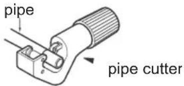
Cut the pipe.
-
Confirm the pipe length according to the distance of the indoor unit.
-
Cut the required pipe with pipe cutter.
-
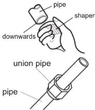
Remove the burrs
-
Remove the burrs with shaper and prevent the burrs from getting into the pipe.
-
Put on suitable insulating pipe.
-
Put on the union nut.
-
Remove the union nut on the indoor connection pipe and outdoor valve; install the union nut on the pipe.
-
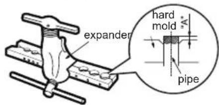
Expand the port
-
Expand the port with expander.
Step 1 is different depending on the diameter, please refer to the table below:
-
Inspection
-
Check the quality of expanding port. If there is any blemish, expand the port again according to the steps above.
smooth surface

improper expanding

leansing

damaged surface

crack uneven thickness
the length is equal
Disposal Considerations
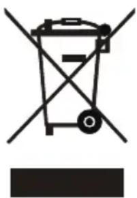
According to the European waste regulation 2002/96/EC this symbol on the product or on its packaging indicates that this product may not be treated as household waste. Instead it should be taken to the appropriate collection point for the recycling of electrical and electronic equipment. By ensuring this product is disposed of correctly, you will help prevent potential negative consequences for the environment and human health, which could otherwise be caused by inappropriate waste handling of this product. For more detailed information about recycling of this product, please contact your local council or your household waste disposal service.
Your product contains batteries covered by the European Directive. 2006/66/EC, which cannot be disposed of with normal household waste. Please check local rules on separate collection of batteries. The correct disposal of batteries helps prevent potentially negative consequences on the environment and human health.
Declaration of Conformity
CE
Producer: Chal-Tec GmbH, Wallstraße 16, 10179 Berlin. Germany
This product is conform to the following European Directives:
2004/108/EC (EMC)
2006/95/EC (LVD)
2011/65/EU (RoHS)
2012/206/EU (ErP)
Cher client,