
VPLFW41L - Projector SONY - Free user manual and instructions
Find the device manual for free VPLFW41L SONY in PDF.

User questions about VPLFW41L SONY
0 question about this device. Answer the ones you know or ask your own.
Ask a new question about this device
Download the instructions for your Projector in PDF format for free! Find your manual VPLFW41L - SONY and take your electronic device back in hand. On this page are published all the documents necessary for the use of your device. VPLFW41L by SONY.
USER MANUAL VPLFW41L SONY
Installation Manual for Dealers Pages 3, 10 to 13 and 42 to 70
This Installation Manual for Dealers explains how to install the projector. For example, it explains lens replacement, installation measurements when using the optional lens and hanging the projector from the ceiling.
Warning: This Installation Manual is for Dealers.
VPL-FE40/FE40L
VPL-FX40/FX40L
VPL-FX41/FX41L
VPL-FW41/FW41L

安全のたてに
Attaching the Projector Suspension Support PSS-610 56
Floor Installation for Twin Stacking 59
56Dimensions 67
59
Français
Table des matieres
Precautions. 14
Aperçu 15
Installation and Decke 50
- Check that the operating voltage of your unit is identical with the voltage of your local power supply. If voltage adaptation is required, consult with qualified Sony personnel.
- Should any liquid or solid object fall into the cabinet, unplug the unit and have it checked by qualified Sony personnel before operating it further.
- Unplug the unit from the wall outlet if it is not to be used for several days.
- To disconnect the cord, pull it out by the plug. Never pull the cord itself.
- The wall outlet should be near the unit and easily accessible.
- The unit is not disconnected from the AC power source (mains) as long as it is connected to the wall outlet, even if the unit itself has been turned off.
- Do not look into the lens while the lamp is on.
- Do not place your hand or objects near the ventilation holes — the air coming out is hot.
- Avoid using an extension cord with a low voltage limited since it may cause the short-circuit and physical incidents.
- Do not catch your finger between the unit and surface of the floor when moving the projector installed on the floor.
- Be careful not to catch your finger in the cooling fan.
- Do not carry the projector with the cabinet on and with its cover open.
Caution
Installation when setting the angle of projection to more than ± 20^
When you set the angle of projection to more than ± 20^ , place a metal tray measuring more than 60~cm × 30~cm at a distance of 30~cm to 50~cm directly below the exhaust vent. Also, take care that no material or water drops fall into the opening of the exhaust vent.
CAUTION
Danger of explosion if battery is incorrectly replaced. Replace only with the same or equivalent type recommended by the manufacturer.
When you dispose of the battery, you must obey the law in the relative area or country.
For kundene i Norge
Dette utstyret kan kobles til et ITstrømfordelingssystem.
On installation
- When the projector is mounted on the ceiling, the Sony PSS-610 Projector Suspension Support must be used for installation.
- Allow adequate air circulation to prevent internal heat build-up. Do not place the unit on surfaces (rugs, blankets, etc.) or near materials (curtains, draperies) that may block the ventilation holes. Leave space of more than 30cm (11^7 / 8 inches) between the wall and the projector. Be aware that room heat rises to the ceiling; check that the temperature near the installation location is not excessive.
- Install the projector on the floor or ceiling. Any other installation causes a mulfunction such as color irregularity or shortening lamp life.
- Do not install the unit in a location near heat sources such as radiators or air ducts, or in a place subject to direct sunlight, excessive dust or humidity, mechanical vibration or shock.
- To avoid moisture condensation, do not install the unit in a location where the temperature may rise rapidly.
- Be sure to secure the cabinet cover firmly when installing to the ceiling firmly.
Warning
For customers who purchase this unit
If customers perform the installation described in this manual, an accident may occur, causing serious injury. Never install it by yourself. For installation, be sure to consult with a Sony dealer.
For dealers
Please read this Installation Manual thoroughly for safe installation.
On illumination
- To obtain the best picture, the front of the screen should not be exposed to direct lighting or sunlight.
- Ceiling-mounted spot lighting is recommended. Use a cover over fluorescent lamps to avoid lowering the contrast ratio.
- Cover any windows that face the screen with opaque draperies.
- It is desirable to install the projector in a room where
floor and walls are not of light-reflecting material. If the floor and walls are of reflecting material, it is recommended that the carpet and wall paper be changed to a dark color.
On preventing internal heat build-up
The projector is equipped with ventilation holes (intake) at the bottom and ventilation holes (exhaust) at the rear. Do not block or place anything near these holes, or internal heat build-up may occur, causing picture degradation or damage to the projector.
On cleaning
- To keep the cabinet looking new, periodically clean it with a soft cloth. Stubborn stains may be removed with a cloth lightly dampened with a mild detergent solution. Never use strong solvents, such as thinner, benzene, or abrasive cleansers, since these will damage the cabinet.
- Avoid touching the lens. To remove dust on the lens, use a soft dry cloth. Do not use a damp cloth, detergent solution, or thinner.
- Clean the filter at regular intervals.
On repacking
- Save the original shipping carton and packing material; they will come in handy if you ever have to ship your unit. For maximum protection, repack your unit as it was originally packed at the factory.
Overview
This manual describes how to install the Sony Data Projection VPL-FE40/FE40L/FX40/FX40L/FX41/ FX41L/FW41/FW41L, how to replace the lens, and installation diagrams. When you replace the lens, also refer to the Operating Instructions.
Replacing the Lens
You can install the following types of optional lenses in the projector:
VPLL-1008 Fixed Short Focus Lens
VPLL-Z1014 Short Focus Zoom Lens
VPLL-Z1024 Middle Focus Zoom Lens
VPLL-Z1032 Long Focus Zoom Lens
Follow the steps below to replace each lens: VPL-FE40/FX40/FX41/FW41 (equipped with standard lens): steps 1 to 5 and, steps 7 to 9 VPL-FE40L/FX40L/FX41L/FW41L (lens optional): steps 1 to 4, and steps 6 to 9
For details on replacing the lens, also refer to the installation manual supplied with the lens.
1 Turn off the power and disconnect the power cable.
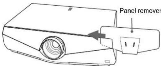
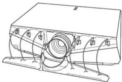
2 Remove the front panel following the steps below. ①Insert the panel remover from the right side of the front panel as the illustration. Then slide the panel remover toward left pinching the front panel.
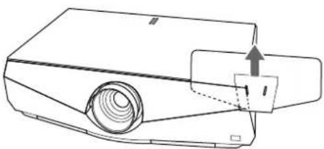
② Pinch the right side of the front panel firmly with the panel remover and slide it until it stops (position in which the edge of the front panel is seen from the hole of the panel remover). Then pull up the panel remover. The right side of the front panel is removed.
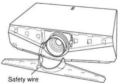
3 Remove the left half of the front panel in the same step, and pick up the front panel. The front panel is connected to the main unit with a wire for safety.
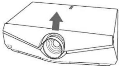
4 Move the lens fixing lever to the lens, then lift it up.
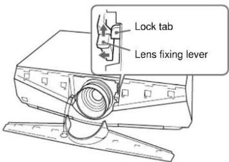
Note
Lift up the lens fixing lever correctly. Otherwise you cannot remove the lens.
5 Withdraw the lens straight forward.
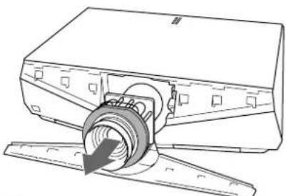
Note
Use both hands to withdraw the lens.
6 Remove the lens hole cover of VPL-FE40L/ FX40L/FX41L/FW41L.
7 Remove two lens caps and the lens connector cover from the replacement lens. Adjust the lens so that the motor section faces up as in illustration ,and check that the cushion around the lens is positioned as in illustration Then insert the lens straight in the direction of the arrow.
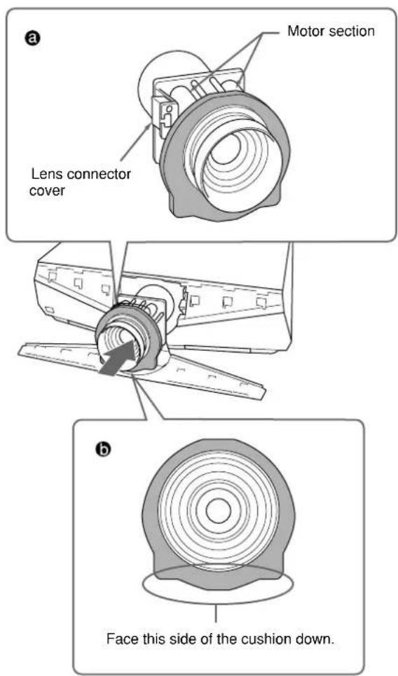
Notes
- If the cushion is not positioned as in illustration b, rotate it by hand. In this case, take care that the cushion does not come off the groove of the lens.
- Change the lens carefully so as not to damage the lens glass with the lever or other parts.
8 Move the lens fixing lever down to the bottom correctly.
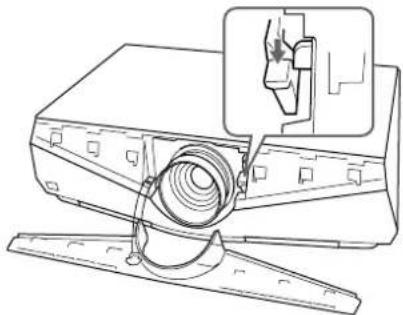
If the lens fixing lever does not move down, the lens may not be fully inserted. Insert it again and move the lens fixing lever down to the bottom correctly.
Note
If the lens does not go in fully, turn the lens slightly right and left slightly.
9 Insert the tab on the rear of the front panel and the plug-in part into the main unit, then hold down the panel so it locks with a click.
Notes
- Take care not to allow the safety wire to protrude.
- After fitting the left and right front panels, check that the top of the front panel does not lift up or protrude from the main unit.
Note on changing lenses
Do not touch the surface of the lens.
Note
When you use the VPLL-1008, do so in the range between +90^ and -90^ (when the lower parts of the lens is a plus) on the basis of installing the VPL-FE40/ FX40/FX41/FW41 horizontally on the floor.
For Dealer
The VPLL-1008 is the lens for rear projection (optical axis angle: 0 degree). When using the VPLL-1008, you should install the projector with the center of the lens aligned with the center of the screen in the horizontal/vertical direction. If you do not do so, a portion of the picture may be invisible.
Also, after installing the lens, we recommend to set "Lens Control" in the Installation menu to "Off".
Précautions
Sécurité
This section describes the examples for installing the projector on the desk, etc. A B
The alphabetical letters in the illustrations, charts and calculation methods indicate the following.
SS : screen size measured diagonally (inches/mm)
a : distance between the screen and the center of the lens
b : distance between the floor and the center of the lens
c : distance between the floor and the bottom of the adjusters of the projector
d : adjustment range of left or right side
x : distance between the floor and the center of the screen, free
N : minimum
M : m a x i m u m
The VPLL-1008 is the lens for rear projection (optical axis angle: 0 degree). When using the VPLL-1008, you should install the projector with the center of the lens aligned with the center of the screen in the horizontal/vertical direction. If you do not do so, a portion of the picture may be invisible.
Also, after installing the lens, we recommend to set "Lens Control" in the Installation menu to "Off".
Français
Distance between the front of the cabinet and the center of the lens
Center of the screen
Centre de l'écran
Ceiling Installation
This section describes the examples for installing the projector on the ceiling. C D
When installing the projector on the ceiling, use the PSS-610 Projection Suspension Support.
For ceiling installation, ask for qualified Sony personnel only.
The alphabetical letters in the illustrations, charts and calculation methods indicate the following.
SS : screen size measured diagonally (inches/mm)
a : distance between the screen and the center of the lens
a' : distance between the screen and the screw hole (on the lens side) for the ceiling bracket
b : distance between the ceiling and the center of the lens
c : distance between the ceiling and the surface of the Suspension Support
when using the PSS-610
using adjustment pipe (b) :
150/175/200 mm (6/7/7/8 inches)
using adjustment pipe (c):
250/275/300 mm (9^7 / 8 / 10^7 / 8 / 11^7 / 8 inches)
d : adjustment range of left or right side
x : distance between the ceiling and the center of the screen, free
N : minimum
M:maximum
Français
PSS-610 Projector Suspension Support (not supplied)
Distance between the front of the cabinet and the center of the lens
Projector/Lens/Center of the lens
Attaching the Projector Suspension Support PSS-610
For more details on the ceiling installation, refer to the Installation manual for Dealers of the PSS-610 Projection Suspension Support. The installation measurements are shown above when you install the projector on the ceiling using the PSS-610.
Top view E
Front view F
Side view
a : distance between the screen and the center of the lens
a': distance between the screen and the screw hole (on the lens side) for the ceiling bracket
1center of the screen
2front of the cabinet
upper ceiling mount bracket
4center of the unit and lens
5ceiling
the bottom surface of the mounting bracket
7 distance between the ceiling and the surface of the mounting bracket
when using the PSS-610
using adjustment pipe (b) :
150/175/200 mm (6/7/7/8 inches)
using adjustment pipe (c):
250/275/300 mm (9 7/8 / 10 7/8 / 11 7/8 inches)
8 center of the lens
Français
When using the standard lens equipped with the VPL-FE40/FX40/FX41/FW41
Floor Installation for Twin Stacking
Available screen size for stacking
80 to 600-inches (2032 to 15240mm ) screens are available for twin stack installation.
This section describes the examples for installing two projectors on the desk using twin-stacking. H
Note
For safety and maintenance purposes, install the projectors away from the wall. Leave a minimum space of 50~cm (19^3 / 4 inches) from both sides and the rear.
Note on stacking
1 Install the projector following the "a" value in the stacking example.
2 Use the zoom to align the pictures from the first and second projectors so that they fill the screen.
The alphabetical letters in the illustrations, charts and calculation methods indicate the following.
SS : screen size measured diagonally (inches/mm)
a : distance between the screen and the center of the lens
b : distance between the floor and the center of the lens of the 1st projector
b: distance between the floor and the center of the lens of the 2nd projector
c : distance between the floor and the adjusters of the 1st projector
c’ : distance between the floor and the adjusters of the 2st projector
x : distance between the floor and the center of the screen, free
N : minimum
M : max i m u m
Français
Ventilation holes (exhaust) /
There is no ventilation hole (intake) and no filter cover on this side on VPL-FX41/FW41.