
SLS1A - Loudspeaker SONY - Free user manual and instructions
Find the device manual for free SLS1A SONY in PDF.
| Product Type | Active line array loudspeaker |
| Brand | Sony |
| Model | SLS1A |
| Dimensions (W×H×D) | 384 mm × 92 mm × 110 mm (with grille) |
| Weight | 4 kg (with grille) |
| Power supply | 100-240 V AC, 50/60 Hz, consumption 87 W (standby 7 W) |
| Frequency range | 80 Hz - 20 kHz |
| Horizontal dispersion | 200° (average 1-4 kHz, -6 dB) |
| Vertical coverage angles | Software adjustable up to 40° (1 module) to 90° (6 modules) |
| Maximum sound pressure level (1 m) | 105 dB (peak 112 dB) for 1 module, up to 121 dB (peak 128 dB) for 6 modules |
| Amplification channels / Power | 10 W × 8 channels (6 ohms, 1 kHz, 1% THD) |
| Amplifier type | Class D |
| Audio inputs | Analog (3-pin terminal block), digital Dante (RJ-45, 1 or 8 channels) |
| Audio outputs | Dante (RJ-45), DC power cascade |
| Connectivity | Dante, Ethernet, Line-Array Speaker Manager app |
| Beam configuration | Via app or DIP switch (6 presets), compatible with EASE Focus 3 and FIRmaker 3D |
| Wall mounting | Mount included, horizontal or vertical installation, anti-detachment device |
| Exterior painting | Acrylic lacquer paint recommended, remove grille before painting |
| Maintenance | Clean with a soft cloth, do not disassemble or modify |
| Included accessories | Grille, power cord, cascade cord, Ethernet cable, brackets, screws, guides |
| Operating temperature | 0 °C to 40 °C |
| Repairability | Contact your Sony distributor in case of malfunction |
| Safety | Use a safety cable, secure firmly, do not obstruct the grille |
| General information | Included documentation: instruction manual, reference guide, online help guide |
Frequently Asked Questions - SLS1A SONY
User questions about SLS1A SONY
0 question about this device. Answer the ones you know or ask your own.
Ask a new question about this device
Download the instructions for your Loudspeaker in PDF format for free! Find your manual SLS1A - SONY and take your electronic device back in hand. On this page are published all the documents necessary for the use of your device. SLS1A by SONY.
USER MANUAL SLS1A SONY
Operating Instructions
Mode d'emploi
This operating instructions manual is provided for construction companies with expertise.
natural_image
Technical line drawing of a rectangular electronic device with a dotted patterned interior (no text or symbols)- 電源コード (1)
natural_image
Technical line drawing of a mechanical component with mounting holes and internal cavities (no text or symbols)https://www.afmg.eu/en
https://www.sony.jp/line-array-speaker/software/
natural_image
Technical line drawing of a mechanical assembly with no visible text or symbolsnatural_image
Technical line drawing of a mechanical device with mounting holes and a lever mechanism (no text or symbols)ご注意
ヒント
natural_image
Repeating pattern of rectangular blocks with circular motifs, no text or symbols presenthttps://www.sony.jp/line-array-speaker/software/
ヒント
Beamタブ
指向性制御設定を行います。
- Import Beam Data
https://www.afmg.eu/en
- Steering/Spread
締め付けトルク:2.0 N·m

natural_image
Technical diagram showing mechanical assembly with arrows indicating direction of movement (no text or symbols present)縦向きに設置する場合
natural_image
Technical line drawing showing a mechanical component with curved arrows indicating rotation or assembly (no text or symbols present)7 安全ワイヤーを壁に固定する。
ご注意
縦向きに設置する場合
natural_image
Technical line drawing of two mechanical components with circular and cross symbols indicating absence or prohibition (no text or labels)natural_image
Diagram of a battery pack with an upward arrow indicating positive movement (no text or symbols present)natural_image
Technical diagram of a mechanical component with labeled parts (no text or symbols present)natural_image
Diagram of a vertical structure with a ladder and mounting bracket, showing an upward arrow (no text or symbols)natural_image
Simple line drawing of a mechanical or architectural component with two circular features and a numbered label (1), no text or symbols present.natural_image
Diagram of a vertical panel with a ladder and circular components, showing an upward force arrow (no text or symbols)スピーカー本体を塗装する
natural_image
Diagram of a vertical structural component with a diagonal arrow indicating force or direction (no text or symbols present)その他
主な仕様
Parts and Controls ....5
Connection and Installation
Connecting with Devices....7
Using the Line-Array Speaker Manager
Application for Setup....15
Using the DIP Switch for Setup.... 16
Wall Mounting....17
Outer Painting....19
Additional Information
Specifications....22
Features
This powered line-array speaker (hereinafter referred to as speaker) is a compact speaker designed with the intention to use in combination with a large display, and provides flexible creation of sound fields, high sound quality, and flexible installation. The main features of the speaker are as follows:
- Fine beam control allows creation of sound field large enough for individual audience areas with a uniform sound pressure.
- The speaker contains magnetic fluid speaker units featuring Sony's proprietary flat and square diaphragm that are arrayed in narrow pitch at equal intervals. It is capable of playing high sound quality contents as well as amplifying audio.
- The speaker supports the Dante® digital audio network interface, as well as the analog input interface, and can be connected with Dante compatible products.
Joining multiple speakers together
Up to 6 speakers can be joined together in accordance with the size of the facility or room where the speakers are installed.
The speaker is capable of supplying power to the adjoining speakers as well. Power can be supplied to up to 3 speakers, including the one connected to an AC outlet by the power cord.
System and beam control setup with the Line-Array Speaker Manager application
Use the Line-Array Speaker Manager application to do the following:
- Placement setup
- Input source setup
- Beam control setup
- Equalizer setup
• Network information viewing - Software update
etc.
Support for EASE® Focus 3 and FIRmaker® 3D
Beam control data exported from the sound simulation software from AFMG® Technologies GmbH can be imported into the Line-Array Speaker Manager application, and then forwarded to the speaker for advanced sound field setup.
Built-in DIP switch
Allows you to select one of the preset beam control settings of the speaker with ease.
About Manuals
Individual manuals available for the speaker provide the following information:
Operating Instructions (this manual)
Provides descriptions on how to connect, install, and configure the speakers.
Reference Guide
Provides important precautions and handling information about the speaker to prevent accidents.
Help Guide


https://rd1.sony.net/help/ha/lsm/h_zz/
Provides descriptions on how to use the Line-Array Speaker Manager application.
Unpacking
- Speaker (1) (with the speaker grille attached) The speaker grille must be removed before painting the speaker enclosure.
natural_image
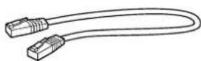
Technical line drawing of a rectangular electronic component with a dotted patterned inner section (no text or symbols)• Power cord (1) The shape of the AC power plug varies depending on region of your residency.
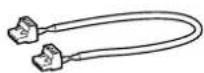
• Power cascade cable (Euro type terminal block (Pitch 5.08 mm, 4-pin, Black/Green)) (1)
- Ethernet cable for audio signal cascade (RJ-45) (1)
• 3-pin Euro type terminal block header (1)
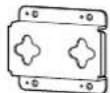
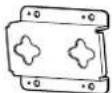
- Speaker bracket (no slant) (2) Speaker bracket (10-degree slant) (2)


- Speaker joint bracket (no slant) (1) Speaker joint bracket (10-degree slant) (1)
• Wall mounting bracket (1)
natural_image
Technical line drawing of a mechanical component with mounting holes and internal cavities (no text or symbols)• Metal joint fitting for wall mounting brackets (1)
- Detachment stopper (2)

• Metal joint fitting for attaching a safety wire (2)

- Cable clamp (2)
- Spacer pad A (2)

- Spacer pad B (1)
- 4×10 screw with washer (9)

- Shoulder screw (2)

- Operating Instructions (this manual) (1)
• Reference Guide (1)
- Warranty card (1)
Parts and Controls
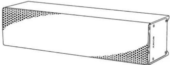
Front
Illustrated below is the front of the speaker with the speaker grille removed.
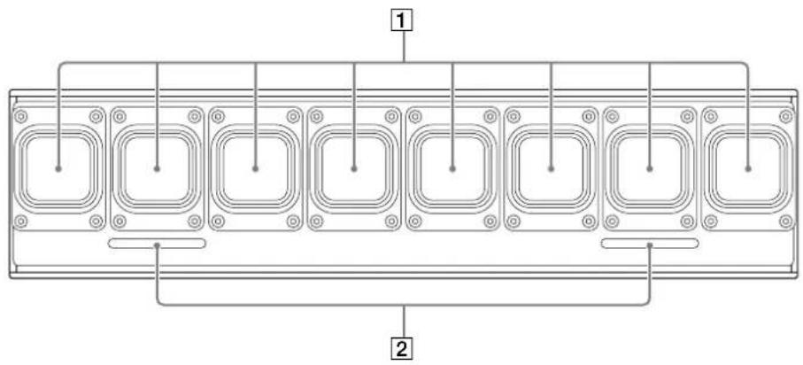
1 Speaker units
2 Bass reflex vents
Rear
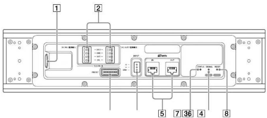
① AC inlet
② Power supply terminals for adjoining speakers (DC IN/DC OUT)
Provided for power supply connection with the adjoining speakers.
3 DIP switch
Provided for changing the number of Dante input channels (1 channel/8 channels) and/or making beam control setup for 1-channel input.

Set to the upper position

: Set to the lower position
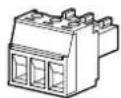
4 Analog input (INPUT) terminal
Provided for connecting an analog audio device using the 3-pin Euro type terminal block header. At the time of purchase, the analog input source is selected. You can change the input source with the Line-Array Speaker Manager application.
⑤ Dante input and output terminals/indicators (Dante IN/Dante OUT)
Provided for connecting a Dante compatible digital device using an Ethernet cable.
Lit in green: Indicates that a network connection is established.
Lit in orange: Indicates that a 1-Gbps or faster communication is in progress.
6 STATUS indicator
Lit (green): Indicates that the speaker is powered.
Lit (red): Indicates that the speaker is on standby.
Flashing (green):
Indicates that the recognition process is in progress.
Flashing (blue):
Indicates that an update is being applied to the speaker.
Flashing (red):
The protection function of the speaker is active. Unplug the power cord from the AC outlet, and then plug it back in to turn on the power. If the speaker remains in the same state after the power recycle, contact your Sony dealer.
Flashing (sequence from green, blue, and to red): Indicates that the speaker is being reset.
7 SIGNAL indicator
Lit (green):
Indicates that input signals are at an appropriate level.
Lit (yellow):
Indicates that Dynamic Range Compression (DRC) is active.
Lit(red):
Indicates that input signals are clipped. Decrease the signal level.
Unlit:
Indicates that the speaker is receiving no input signals.
8 RESET button
Provided for restoring the default state of the speaker. Use a long thin object, such as a hair pin, to push the button all the way in.
Dimensions
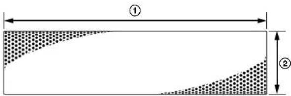
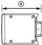
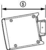
① Width: Approx. 384 mm (15 ^1 /8 in)
② Height: Approx. 92 mm (3 ^5 /8 in)
③ Depth: Approx. 110 mm (4 ^8 /8 in)
(with the speaker bracket unattached)
④ Depth: Approx. 114 mm (4/2 in)
(with the speaker bracket (no slant) attached)
⑤ Depth: Approx. 122 mm (47/8 in)
(with the speaker bracket (10-degree slant)
attached)
Connection and Installation
Connecting with Devices
System Configuration and Setup Flow
The following three approaches are available for audio setup. Choose one of the approaches in accordance with the size of installation facility or the devices to connect for installation.
Approach 1: Using the Line-Array Speaker Manager application for setup with performing a sound simulation in advance
Approach 2: Using the Line-Array Speaker Manager application for setup without performing a sound simulation Approach 3: Using the DIP switch for setup
Approach 1: Using the Line-Array Speaker Manager application for setup with performing a sound simulation in advance
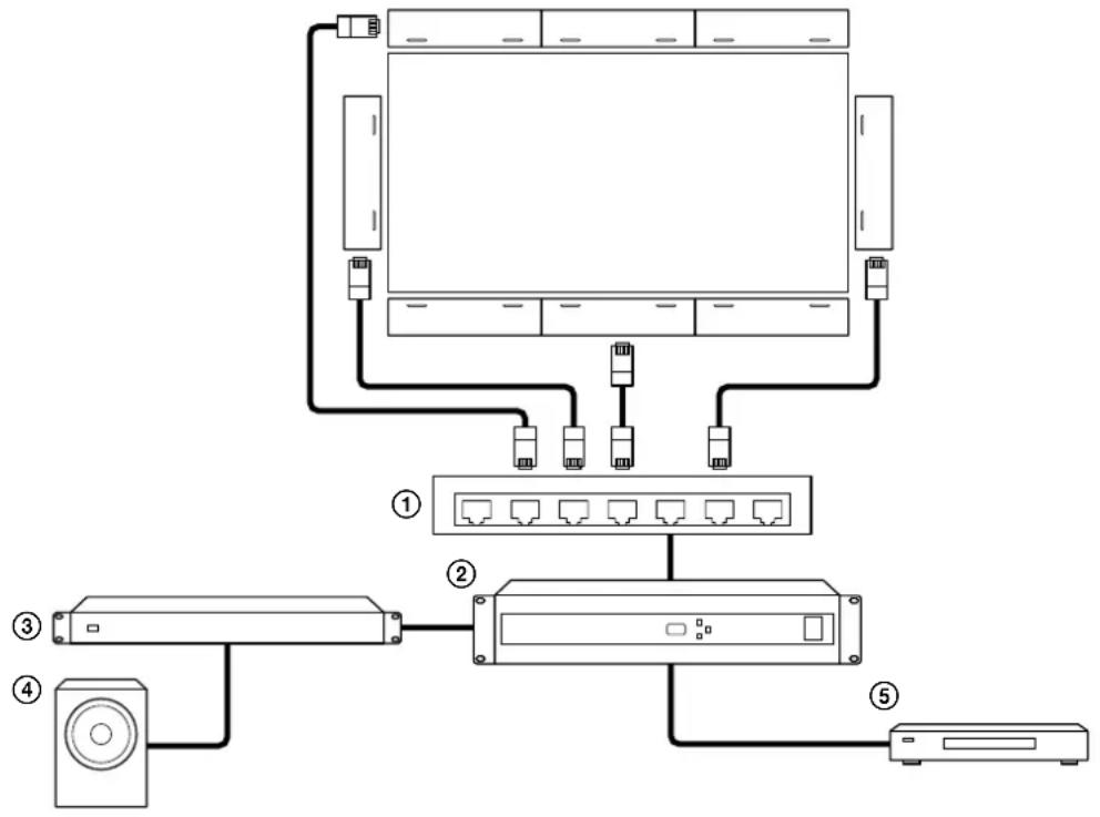
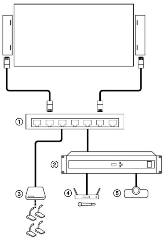
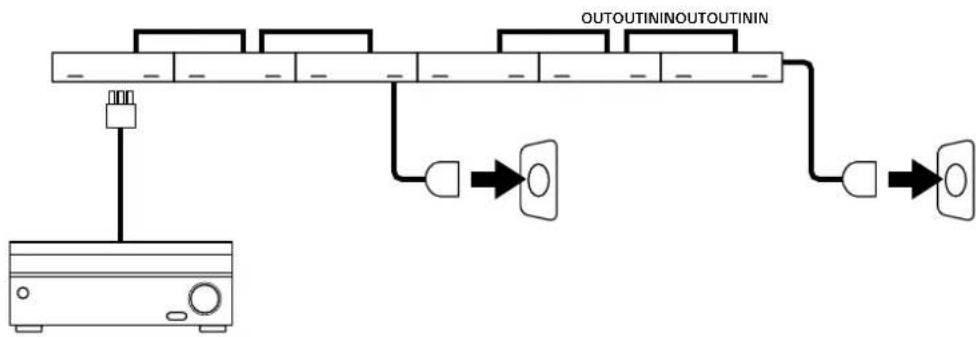
The following shows a connection example in a large facility and the speakers are located on the top, bottom, left and right of the large screen display.
Connect the speakers with Dante compatible audio devices using Ethernet cables. Via a network switch ①), connect the speakers to a digital signal processor (②) that has, among others, a power amplifier (③), a subwoofer (④), and a video player (⑤) connected.
flowchart
graph TD
    A["Monitor"] --> B["Switch ①"]
    A --> C["Switch ②"]
    A --> D["Switch ③"]
    A --> E["Switch ④"]
    A --> F["Switch ⑤"]
Configuration
1 Perform a sound simulation with EASE Focus 3 and FIRmaker 3D.
- EASE Focus 3 and FIRmaker 3D can be downloaded from the website of AFMG Technologies GmbH at: https://www.afmg.eu/en
- EASE Focus 3 data for the speaker can be downloaded from the website at: https://pro.sony/products/professional-speakers/SLS-1A
2 Join the speakers together (page 11).
3 Connect audio devices to the speakers, and then the speakers to AC outlets with the power cords.
4 Mount the speakers on a wall (page 17).
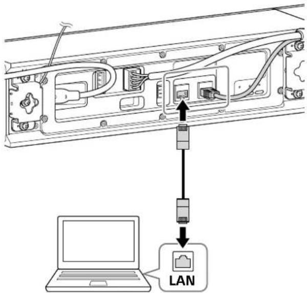
5 Connect a computer to one of the speakers using an Ethernet cable and make setup of the speaker, such as speaker placement, with the Line-Array Speaker Manager application (page 15).
Approach 2: Using the Line-Array Speaker Manager application for setup without performing a sound simulation
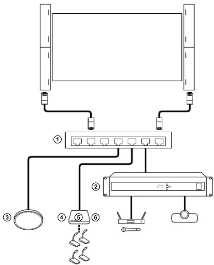
The following shows a connection example for using the speakers in a large conference room or classroom. Connect the speakers with Dante compatible audio devices using Ethernet cables. Via a network switch ①), connect the speakers with such devices as follows:
- Beamforming microphone (③)
• Conference microphone system (④) - Digital signal processor (②) that has, among others, a wireless microphone (⑤) and a video conference system (⑥) connected
flowchart
graph TD
    A["Server"] --> B["Switch"]
    B --> C["Device 1"]
    B --> D["Device 2"]
    B --> E["Device 3"]
    B --> F["Device 4"]
    B --> G["Device 5"]
    B --> H["Device 6"]
Configuration
1 Join the speakers together (page 11).
2 Connect audio devices to the speakers, and then the speakers to AC outlets with the power cords.
3 Mount the speakers on a wall (page 17).
4 Connect a computer to one of the speakers using an Ethernet cable and make setup of the speaker, such as speaker placement and beam control, as well as equalizer setup with the Line-Array Speaker Manager application (page 15).
Approach 3: Using the DIP switch for setup
The following shows a connection example for using the speakers in a medium size conference room with easy setup. Connect the speakers with Dante compatible audio devices using Ethernet cables. Via a network switch (①), connect the speakers with such devices as follows (To use Dante devices, you need to specify the input source, in advance, with the Line-Array Speaker Manager application (page 15).):
• Conference microphone system (③)
- Digital signal processor (②) that has, among others, a wireless microphone (④) and a video conference system (⑤) connected
flowchart
graph TD
    A["Server"] --> B["Router"]
    B --> C["Sensor"]
    C --> D["Network Switch"]
    D --> E["Sensor"]
    E --> F["Sensor"]
    style A fill:#f9f,stroke:#333
    style B fill:#ccf,stroke:#333
    style C fill:#cfc,stroke:#333
    style D fill:#fcc,stroke:#333
    style E fill:#cff,stroke:#333
    style F fill:#ffc,stroke:#333
Configuration
1 Select one of the preset beam control settings with the DIP switch (page 16).
2 Connect audio devices to the speakers, and then the speakers to AC outlets with the power cords.
3 Mount the speakers on a wall (page 17).
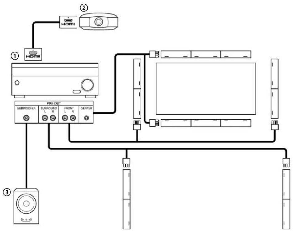
Approach 4: Using the speakers in combination with an AV receiver or a projector at home
Connect the speakers with analog audio devices using the 3-pin Euro type terminal block headers.
Connect the speakers with an AV receiver (①) or equivalent that has a home projector (②) or a subwoofer (③) connected.
You can place the speakers in the center, front, and rear, and then distribute audio input from the AV receiver to the speakers.
flowchart
graph TD
    A["①"] --> B["PRE OUT"]
    C["②"] --> B
    D["③"] --> E["Speaker"]
    B --> F["Subwoofer"]
    B --> G["Surround L R"]
    B --> H["Front L R"]
    B --> I["Center"]
    F --> J["Resistor"]
    G --> K["Resistor"]
    H --> L["Resistor"]
    I --> M["Resistor"]
Configuration
1 Perform a sound simulation with EASE Focus 3 and FIRmaker 3D.
- You can also set up the beam control by using the Line-Array Speaker Manager application without performing a sound simulation.
- EASE Focus 3 and FIRmaker 3D can be downloaded from the website of AFMG Technologies GmbH at: https://www.afmg.eu/en
- EASE Focus 3 data for the speaker can be downloaded from the website at: https://pro.sony/products/professional-speakers/SLS-1A
2 Join the speakers together (page 11).
3 Connect the speakers with an AV receiver that has a built-in pre out terminals.
4 Connect the speakers to AC outlets with the power cords.
5 Mount the speakers on a wall (page 17).
6 Set up the speakers with the Line-Array Speaker Manager application (page 15). In addition, make appropriate settings, as needed, on the AV receiver.
Joining Multiple Speakers Together
This section describes the procedure to join multiple speakers together.
Note
- When joining the speakers with the attached speaker grille facing down, take a shock-absorbing measure, for example placing the speakers on their packaging materials (Styrofoam packing materials), in advance. The shape of the packaging materials may differ from the illustration.
natural_image
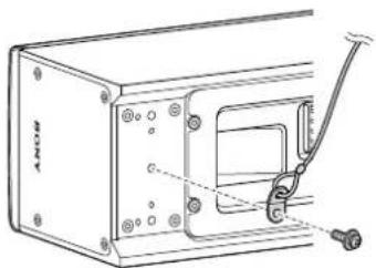
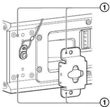
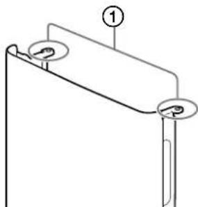
Technical line drawing of a mechanical component with internal channels and mounting brackets (no text or symbols)1 Attach the metal joint fitting for attaching a safety wire and a safety wire (commercially available) to either end of the rear surface of the speaker with a 4×10 screw with washer.
Tightening torque: 2.0 N·m
natural_image
Technical line drawing of a mechanical device with mounting holes and a lever mechanism (no text or symbols)Note
- Depending on the region of your residency, it may be required by law to employ, at the time of installation, multiple measures to protect the speaker from falling off. When multiple measures are not required, however, it is still recommended that a safety wire be used for a measure to enhance safety.
Check an installation site, an installation procedure, and tools for compliance with the building standards and regulations before installation.
For details, follow the instructions provided by the manufacturer of the safety wire.
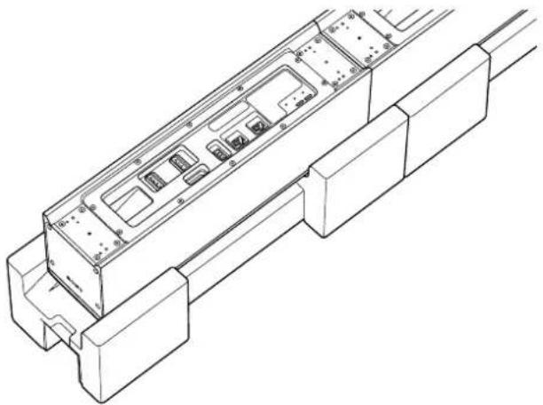
2 Attach the speaker bracket to the rear surface of the speaker with a 4×10 screw with washer.
Using the dowels and the dowel holes as reference points for positioning, align the position of the speaker bracket for attachment (①).
To the joint section of the first and second speakers, attach the speaker joint bracket with 4×10 screws with washers.
Tightening torque: 2.0 N·m
When using only one speaker, attach the speaker bracket to either end of the speaker.
Note
- When attaching the speaker joint bracket, put a linear object, such as a ruler, against the adjoining speakers to keep them aligned straight.
Hint
- For bundling cables, attach the cable clamp (2) together with the speaker bracket.
- Pull out the safety wire through a corner gap between the speaker bracket and the speaker.
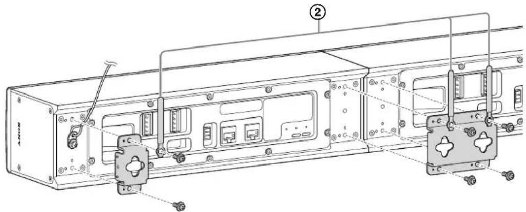
3 Connect cables.
- Plug the power cord (①) into the AC inlet.
- Connect one end of the power cascade cable (②) to the power supply terminal (DC OUT) for adjoining speakers on the first speaker, and then the other end to the power supply terminal (DC IN) for adjoining speakers on the adjoining (second) speaker.
- To connect the joined speakers, connect the Dante output terminal (Dante OUT) on one speaker and the Dante input terminal (Dante IN) on the other with the Ethernet cable (supplied) (③).
- To connect a device, such as a Dante compatible digital device or a network switch, to the speaker, connect the device to the Dante input terminal (Dante IN) on the speaker with an Ethernet cable (commercially available) (4).
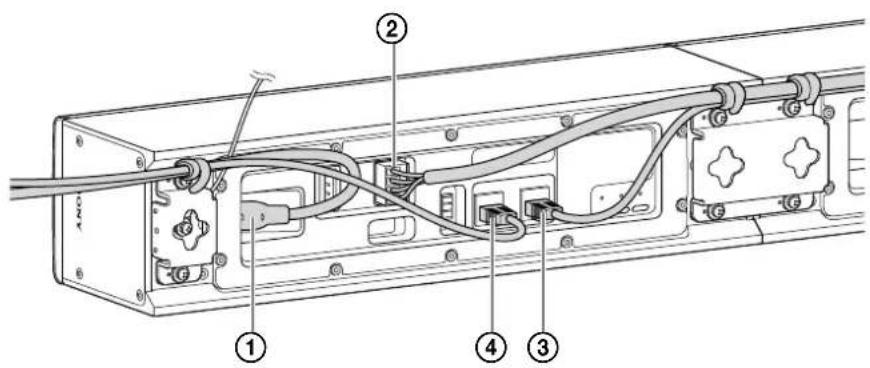
Hint
- The connector (header) at either end of the power cascade cable is colored in black or green.
Plug the connector into the power supply terminal for adjoining speakers (DC OUT: black/DC IN: green) in the same color.
• To prevent cables from sticking out of the speaker, bundle them together with the cable clamp. - To connect with an analog audio device, connect the analog audio device to the analog input terminal using the 3-pin Euro type terminal block header.
- When using an Ethernet cable other than the supplied one for connection, choose a cable of CAT5e or higher class.
4 Repeat steps 1 through 3 to join another speaker.
When the power cascade cable is not long enough for connection
When the power cascade cable is not long enough for connection, alter a cable (commercially available) as illustrated below:
- Use a 16 gauge cable for alteration.
- For the US customers, it is required to use a cable that meets the National Electrical Code (NEC) Class 2 or Class 3 requirements for alteration.
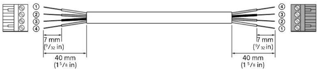
①: White SEL
②: Green DET
③: Black GND
④: Red 24 V
④: Red 24 V
③: Black GND
②: Green DET
①: White SEL
Wiring examples with an analog audio device
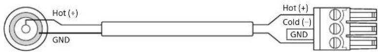
For connection with an analog audio device using the 3-pin Euro type terminal block header and an analog audio cable, see the following examples for wiring:
Balanced wiring (example with the XLR cable*)
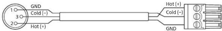
* Assignments to the pins 1, 2, and 3 of the XLR terminal vary depending on the analog audio device.
Unbalanced wiring (example with the RCA cable)
To join 6 speakers together
1 As illustrated below, have 2 sets of 3 speakers, which are joined together by the speaker joint brackets, ready at hand.

flowchart
graph LR
    A["Input Box 1"] --> B["Output Box 1"]
    C["Input Box 2"] --> D["Output Box 2"]
    E["Input Box 3"] --> F["Output Box 3"]
    G["Input Box 4"] --> H["Output Box 4"]
2 Plug the power cord into the AC inlet on the speaker.
Power can be supplied to up to 3 adjoining speakers through a single power cord. Connect the left and right pairs of the 3 adjoining speakers using 2 power cascade cables and connect all of the 6 speakers together using Ethernet cables.
flowchart
graph TD
    A["Power Supply Unit"] --> B["Switch"]
    B --> C["Output Terminal 1"]
    C --> D["Logic Gate"]
    D --> E["Output Terminal 2"]
    E --> F["Logic Gate"]
    F --> G["Output Terminal 3"]
    G --> H["Output Terminal 4"]
    H --> I["Output Terminal 5"]
    I --> J["Output Terminal 6"]
    J --> K["Output Terminal 7"]
    K --> L["Output Terminal 8"]
    L --> M["Output Terminal 9"]
    M --> N["Output Terminal 10"]
    N --> O["Output Terminal 11"]
    O --> P["Output Terminal 12"]
    P --> Q["Output Terminal 13"]
    Q --> R["Output Terminal 14"]
    R --> S["Output Terminal 15"]
    S --> T["Output Terminal 16"]
    T --> U["Output Terminal 17"]
    U --> V["Output Terminal 18"]
    V --> W["Output Terminal 19"]
    W --> X["Output Terminal 20"]
    X --> Y["Output Terminal 21"]
    Y --> Z["Output Terminal 22"]
    Z --> AA["Output Terminal 23"]
    AA --> AB["Output Terminal 24"]
    AB --> AC["Output Terminal 25"]
    AC --> AD["Output Terminal 26"]
    AD --> AE["Output Terminal 27"]
    AE --> AF["Output Terminal 28"]
    AF --> AG["Output Terminal 29"]
    AG --> AH["Output Terminal 30"]
3 Join 6 wall mounting brackets together as illustrated below, and then mount the speakers on a wall.
For details, see "Wall Mounting" (page 17).

natural_image
Repeating pattern of interlocking rectangular blocks with circular motifs (no text or symbols)Using the Line-Array Speaker Manager Application for Setup
Make setup of the speaker with the Line-Array Speaker Manager application. For detailed instructions, refer to the Help Guide (https://rd1.sony.net/help/ha/lsm/h_zz/).
1 Join the speakers together, connect audio devices, and connect the speakers to AC outlets (page 7).
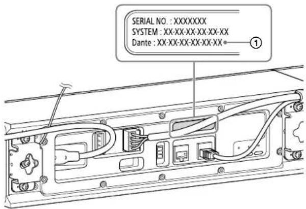
2 View the MAC address (①) of the speaker.
3 Install the Line-Array Speaker Manager application on a computer.
The Line-Array Speaker Manager application can be downloaded from the website at: https://pro.sony/products/professional-speakers/SLS-1A
4 Connect the computer to the same network as the speaker, using an Ethernet cable.
Hint
- The computer and the speaker may not necessarily be connected directly. When a network switch and a router are used, the computer and the speaker can be connected via them as well.
5 Start the Line-Array Speaker Manager application.
If the "Device Detection" window opens, make sure that the speaker and other devices connected with the computer are detected, and then click [OK].
Placement tab
Specify the placement of the speaker.
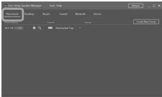
View the MAC address of the speaker (displayed as "SLS-1A-MAC Address").
You can change the placement setup or the name of the speaker.
6 Make system setup.
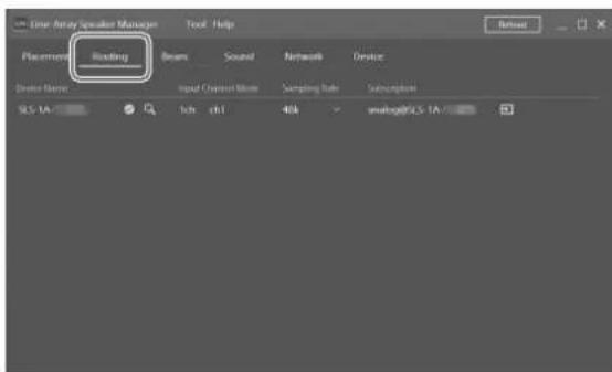
Routing tab
You can view or change the input source.
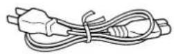
Beam tab
You can make beam control setup.
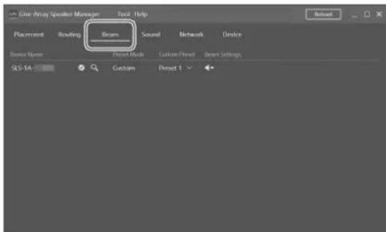
- Import Beam Data
You can import sound simulation data from EASE Focus 3 and FIRmaker 3D.
EASE Focus 3 and FIRmaker 3D can be downloaded from the website of AFMG Technologies GmbH at: https://www.afmg.eu/en
- Steering/Spread Adjust the beam steering angle (between -40 degrees and +40 degrees) and the opening angle (between 0 degree and 90 degrees).
Sound tab
Make setup of the equalizer and others.
Network tab
You can view the MAC address or IP address of the Dante device or the speaker.
Device tab
You can view the connection state, apply software updates to the speaker, or restart the speaker.
Using the DIP Switch for Setup
Instead of the Line-Array Speaker Manager application, you use the DIP switch on the rear of the speaker to make beam control setup of the speaker.
Changing the Number of Dante Input Channels (1 Channel/8 Channels)
To select 1-channel input, set the left-most slider of the DIP switch to the lower position.
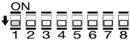
To select 8-channel input, set the left-most slider of the DIP switch to the upper position.
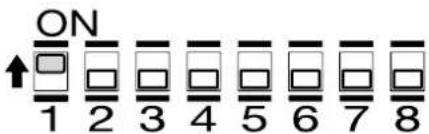
Note
- While 8-channel input is selected, no beam control is applied to the speaker.
• After you change the number of Dante input channels, turn off the power to the speaker and then turn it back on.
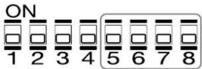
Changing the Beam Control Setup
Using the 4 sliders to the right of the DIP switch, you can select one of the 6 preset beam control settings.
Note
- Before making beam control setup with the Line-Array Speaker Manager application, set the sliders of switches 5, 6, 7, and 8 of the DIP switch to the lower positions.
| Preset | For horizontal placement | For vertical placement | DIP switch configuration |
| 1 | 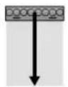 | ||
| 2 | 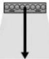 | ||
| 3 | 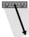 | ||
| 4 | 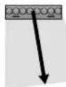 | ||
| 5 | 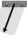 | ||
| 6 | 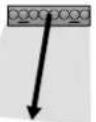 |
Wall Mounting
- Before mounting the speakers on a wall, follow the steps in "Joining Multiple Speakers Together" to have them ready for wall mounting. (page 11)
- Mount the speakers securely on a wall while giving adequate attention to safety matters.
Sony assumes no liability for accidents and/or damage you may suffer as a result of inadequate mounting, insufficient mounting strength, improper use, natural disasters, etc.
- You can paint the speaker grille and/or the speaker enclosure as well. (page 19)
1 Choose a mounting location on a wall.
2 Attach the wall mounting bracket on the wall with wood screws (commercially available) or equivalents.
Hint
- Use a level to attach the wall mounting bracket so that the bracket comes horizontal to the earth.
- The hole indicated by "a" in the following figure is located at the middle point along the longer edge of the wall mounting bracket. Use this hole as a reference for attachment.
- For wall mounting, use screws with the diameter of 6 mm - 8 mm (1/4 in - 11/32 in) or equivalent and flat washers with the outside diameter of 18 mm (23/32 in).
- When wiring cables, do it along the cutout (①) side of the wall mount bracket.
For horizontal installation
Use the above figure as a reference for attachment.
For vertical installation
The orientation of the wall mounting bracket is not relevant.
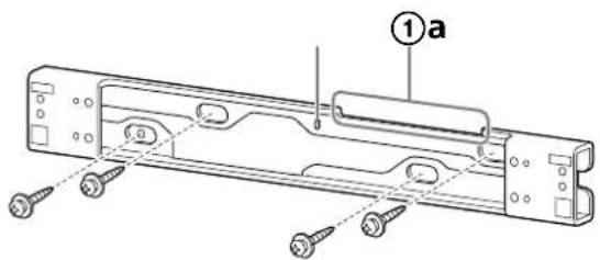
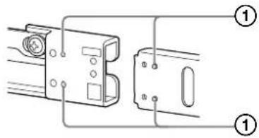
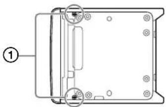
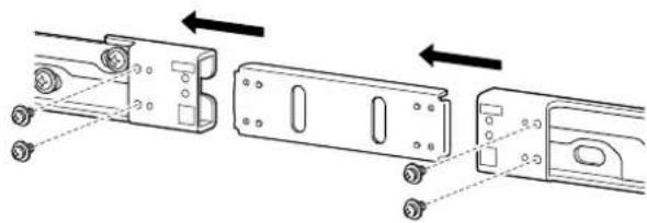
3 For installing multiple speakers that are joined together, use the metal joint fitting for wall mounting brackets to join the wall mounting brackets together.
Align the metal joint fitting with the wall mounting bracket using the dowels and dowel holes on them as reference points for positioning (①), and then secure them together with 4×10 screws with washers.
Tightening torque: 2.0 N·m
natural_image
Technical diagram showing three mechanical components with arrows indicating assembly or alignment (no text or symbols present)Follow the instructions in step 2 and attach the joined wall mounting brackets to the wall.
4 Fasten the shoulder screws to the wall mounting bracket and adhere the spacer pads.
Tightening torque: 2.0 N·m
For horizontal installation
Shoulder screws: Secure each to the location indicated by "H" (①).
Spacer pads: Adhere the square ones to the two locations at the left and right ends of the wall mounting bracket.
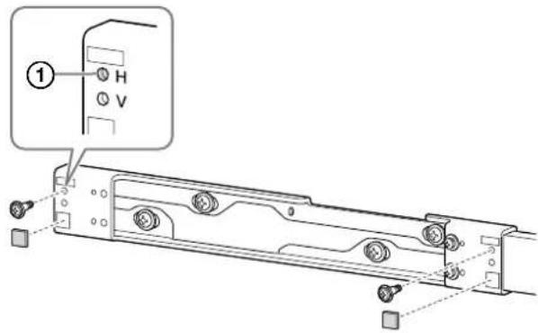
For vertical installation
Shoulder screws: Secure each to the location indicated by "V" (②).
Spacer pads: Adhere the square ones to the two locations at the top and bottom ends of the wall mounting bracket and the rectangle one to the location at the top end.
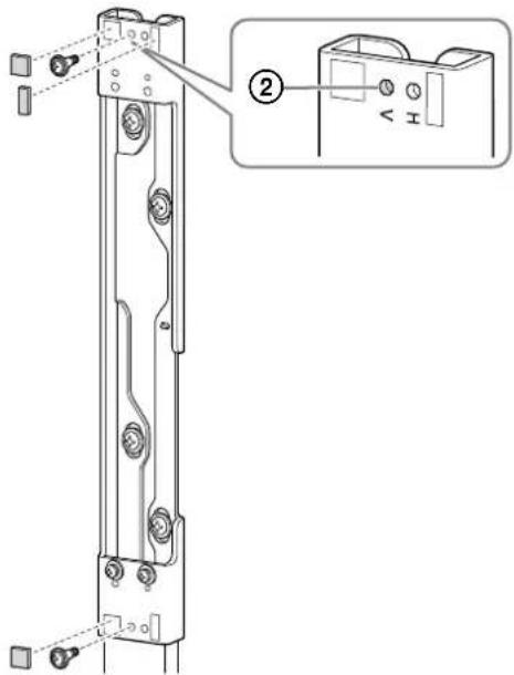
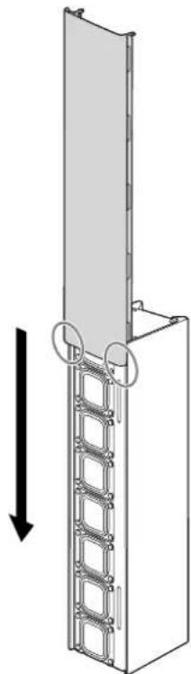
5 Hook the speaker bracket over the shoulder screws that are fastened to the wall mounting bracket.
Place the speaker so that its side with the bass reflex vents comes closer to the display or screen.
natural_image
Technical line drawing of a mechanical component with curved arrows indicating rotation or assembly (no text or symbols)6 Attach the detachment stopper to either end of the wall mounting bracket.
Align the detachment stopper with the speaker bracket using the dowels and dowel holes on them as reference points for positioning (①), and then secure them together a 4×10 screw with washer.
Tightening torque: 2.0 N·m
7 Secure the safety wire to the wall.
Note
- Use screws (commercially available) adequate to the wall material and strength. Depending on the wall material, use of an inadequate screw may damage the wall.
- Secure the speaker horizontally or vertically on a re-enforced wall.
- Request your dealer or a construction company to do secure mounting work with thorough consideration for safety.
- Sony assumes no liability for any accident or damage arising from improper mounting, insufficient mounting strength, improper use, natural disasters, etc.
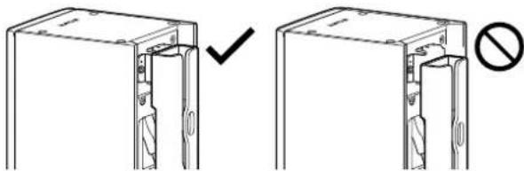
8 Confirm that wall mounting is complete.
Make sure of the following:
- None of the cables is twisted or pinched.
Warning
- Improper wiring of cables, including the power cord, may cause a short circuit, resulting in an electrical shock or a fire. For your safety, make sure that wall mounting is complete.
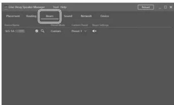
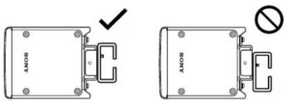
Note
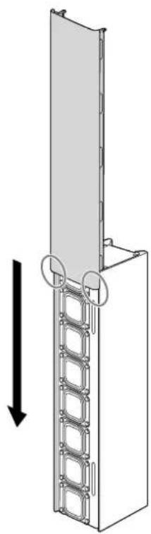
- Secure the speaker as illustrated below:
Horizontal installation
Vertical installation

natural_image
Technical line drawing showing two views of a mechanical component with a checkmark and no symbol (no text or labels)- For horizontal installation, secure the speaker by sliding it downward.
The speaker is not secured before it is slid down.
Make sure that the speaker is securely hooked over the shoulder screws. - For vertical installation, secure the speaker by sliding it downward while pressing it against the wall.
The speaker is not secured before it is slid down.
Make sure that the speaker is securely hooked over the shoulder screws.
Outer Painting
For outer painting of the speaker, it is recommended to use acrylic lacquer paint.
Warning
Except for the purpose of outer painting, do not attempt to disassemble or modify the speaker to avoid the risk of electric shocks, fires, injuries, or malfunctions.
Caution
While painting, be sure to allow adequate ventilation. When removing and attaching the speaker grille, be sure to avoid harming yourself.
Note
- While using a volatile solvent, watch out for fire to avoid the risk of fires and accidents.
- Sony assumes no guarantee regarding the damage caused by painting.
Painting the Speaker Grille
Remove the speaker grille from the speaker before painting.
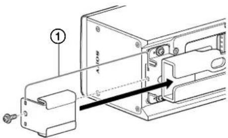
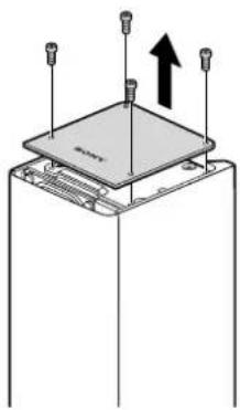
1 Remove the 4 screws securing the outer lid to the right end of the speaker, and then remove the lid.
natural_image
Diagram of a mechanical assembly with three pins and an upward arrow indicating motion (no text or symbols)2 Remove the 2 screws (①) securing the speaker grille.
3 As illustrated below, remove the speaker grille by sliding it out in the direction of the arrow.
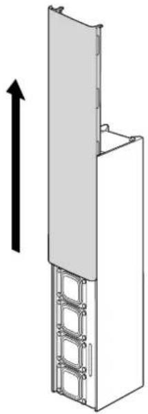
natural_image
Diagram of a vertical structure with a sloped top and metal frame, showing an upward arrow (no text or symbols)4 Wipe clean the speaker grille before painting.
Do not file the speaker grille.
5 Spray the paint over the speaker grille.
Note
- Prevent the speaker grille from being clogged by the paint to avoid the risk of poor sound quality.
- Be sure to let the paint completely dry.
- Mask the screw fastening sections on the speaker grille (①) to prevent them from being sprayed over.
To paint the speaker enclosure, proceed to "Painting the Speaker Enclosure" (page 21).
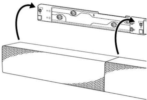
6 Attach the outer lid and the speaker grille, which you removed in steps 1 through 3, back into position, and then secure them with the screws.
When attaching the speaker grille, align its end with the speaker end, and then slide in the speaker grille along the speaker enclosure.
natural_image
Diagram of a vertical panel structure with a roller stack and directional arrow (no text or symbols)Painting the Speaker Enclosure
1 Before painting, follow the instructions in steps 1 through 3 in "Painting the Speaker Grille" (page 19) to remove the outer lid and the speaker grille, and then wipe clean the speaker enclosure.
Do not file the speaker enclosure.
2 Spray the paint over the speaker enclosure.
Note
- To prevent the speaker units and the connection terminals from being exposed to the paint, cover them with a masking material before painting.
- While painting, keep the speaker units untouched.
- Be sure to let the paint completely dry.
3 Attach the outer lid and the speaker grille, which you removed in steps 1 through 3 in "Painting the Speaker Grille" (page 19), back into position, and then secure them with the screws.
When attaching the speaker grille, align its end with the speaker end, and then slide in the speaker grille along the speaker enclosure.
natural_image
Diagram of a vertical panel structure with a double-headed arrow indicating downward motion (no text or symbols present)Additional Information
Specifications
| System | ||||||
| Module (1 module) (2 modules) | 3 modules | 4 modules | 5 modules | (6 modules) | ||
| Frequency Range* Depends on the frequency response measured in an anechoic chamber. | 80 Hz - 20 kHz | |||||
| Horizontal Dispersion* 1 - 4 kHz average, -6 dB For vertical installation (Vertical Dispersion for horizontal installation) | 200 degrees | |||||
| Vertical Opening Angles* For vertical installation (Horizontal Opening Angles for horizontal installation) | SoftwareAdjustable:Max40 degrees | SoftwareAdjustable:Max50 degrees | SoftwareAdjustable:Max60 degrees | SoftwareAdjustable:Max70 degrees | SoftwareAdjustable:Max80 degrees | SoftwareAdjustable:Max90 degrees |
| Vertical Beam Steering Angles* For vertical installation (Horizontal Beam Steering Angles for horizontal installation) | 20 degrees | 20 degrees | 30 degrees | 40 degrees | 40 degrees | |
| Maximum Sound Pressure Level (1 m)* The value for Module 1 is calculated based on the actual value measured without beam control in an anechoic chamber.The values for Modules 2 to 6 are calculated based on the Module 1 value. | 105 dB(peak 112 dB) | 111 dB(peak 118 dB) | 115 dB(peak 122 dB) | 117 dB(peak 124 dB) | 119 dB(peak 126 dB) | 121 dB(peak 128 dB) |
| Peak Sound Pressure Level (30 m)* 15 dB signal loss per 30 m is assumed. | 97 dB 103 dB | 107 dB 109 dB | 111 dB 113 dB | |||
| Typical Usable Throw Distance* Typical Maximum Usable Throw Distance includes considerations for reverberation and speech intelligibility. | 4 m 8 m | 12 m 16 m | 20 m | 25 m | ||
| Low-frequency Beam Control Limit | 1.25 kHz 630 | Hz 400 Hz 315 | Hz 250 Hz 200 | Hz | ||
| Enclosure type | Bass reflex type | |||||
| Driver | Flat and Square speaker unit, 35 mm × 35 mm (17/16 in × 17/16 in) Full range × 8 | |||||
| Magnetic shielding | No | |||||
| Dust and water resistant | No | |||||
| Amplifier Channels / Rated Power | Power Output (rated)10 W × 8 channels (at 6 ohms, 1 kHz, 1% THD) | |||||
| Amplifier type | Class-D | |||||
| Protection circuit | Speaker processing: Clipping limitAmplifier: Short circuit protection/Overheat protection/Over voltage protection/Under voltage protection/DC protectionPower unit: Overload protection/Overheat protection | |||||
| Electric performance | ||||||
| Power (AC) Voltage | UniversalAC 100 V - 240 V, 50 Hz/60 Hz | |||||
| Power (AC) Connector | IEC60320-C7 | |||||
| Power Consumption | 87 W/Standby 7 W (Dante IN or Dante OUT: 1 port), 8 W (Dante IN and Dante OUT: 2 ports) | |||||
| Input/Output | ||||||
| Analog Audio Input | Euro type terminal block (Pitch 3.81 mm, 3-pin, Green) | |||||
| Analog Audio Maximum Input Level (4 stages) | Balance connection: +8.2 dBu (2 Vrms)/+12 dBu/+18 dBu/+24 dBuUnbalance connection: +8.2 dBu (2 Vrms)/+12 dBu/+18 dBu | |||||
| Input Sensitivity (4 stages) | Balance connection: +8.2 dBu (2 Vrms)/+12 dBu/+18 dBu/+24 dBuUnbalance connection: +8.2 dBu (2 Vrms)/+12 dBu/+18 dBu | |||||
| Input Impedance | Balance connection: 94 kΩ / Unbalance connection: 47 kΩ | |||||
| Digital Audio Inputs | 1-channel of Dante digital audio network (RJ-45)*8-channel of Dante digital audio network (RJ-45) is possible | |||||
| Digital Audio Outputs | 1-channel of Dante digital audio network (RJ-45)*8-channel of Dante digital audio network (RJ-45) is possible | |||||
| Power (DC) Input/Output | Euro type terminal block (Pitch 5.08 mm, 4-pin, Black/Green) | |||||
| DIP Switch | Select preset beam setting and Dante input channel (1ch/8ch) | |||||
| Integrated DSP | ||||||
| A/D and D/A Converters | 24-bit, 96 kHz | |||||
| FIR Filter Support | 1 024 tap @ 96 kHz | |||||
| Audio Latency | 13 ms | |||||
| Physical specifications | |
| Enclosure | Cabinet: Extruded aluminum (powder coated)Side/Back panel: Plastic |
| Grille | Punching metal steel plate (Painted) |
| Indicators | Status, Signal, LAN |
| Operating Temperature Range (Ambient) | 0 °C - 40 °C (32 °F - 104 °F) |
| Cooling System | Cooling is passive only |
| Environmental | Indoor only |
| Install | The installation angle can be adjusted either to 0 degree or to 10 degrees in the horizontal direction by the supplied wall mounting bracket and speaker brackets. |
| Dimensions (w×h×d)(approx.) | 384 mm × 92 mm × 100 mm (15 1/8 in × 3 5/8 in × 4 in) (without speaker grille)384 mm × 92 mm × 110 mm (15 1/8 in × 3 5/8 in × 4 3/8 in) (with speaker grille) |
| Mass (approx.) | 4 kg (8 lb 14 oz) (with speaker grille) |
| Included Accessories | Speaker grille (attached to the speaker) (1), Power cord (1),Power cascade cable (Euro type terminal block) (1),Ethernet cable for audio signal cascade (RJ-45) (1),3-pin Euro type terminal block header (1), Speaker bracket (no slant) (2),Speaker bracket (10-degree slant) (2), Speaker joint bracket (no slant) (1),Speaker joint bracket (10-degree slant) (1), Wall mounting bracket (1),Metal joint fitting for wall mounting brackets (1), Detachment stopper (2),Metal joint fitting for attaching a safety wire (2), Cable clamp (2), Spacer pad A (2),Spacer pad B (1), 4×10 screw with washer (9), Shoulder screw (2),Operating Instructions (this manual) (1), Reference Guide (1), Warranty card (1) |
Trademarks
- Dante® is registered trademarks of Audinate Pty Ltd.
- EASE ^ , FIRmaker ^ and AFMG ^ are registered trademarks of AFMG Technologies GmbH.
- All other trademarks and registered trademarks are trademarks or registered trademarks of their respective holders. In this manual, ^™ and ^® marks are not specified.
Licenses
- This product contains software that Sony uses under a licensing agreement with the owner of its copyright. We are obligated to announce the contents of the agreement to customers under requirement by the owner of copyright for the software. Please access the following URL and read the contents of the license.
https://rd1.sony.net/help/ha/sl/22la/

- The software included in this product contains copyrighted software that is licensed under the GPL/LGPL and other licenses which may require access to source code. You may find a copy of the relevant source code as required under the GPL/LGPL (and other licenses) at the following URL. You may obtain the source code as required by the GPL/LGPL on a physical medium from us for a period of three years after our last shipment of this product by applying through the form at the following URL.
This offer is valid to anyone in receipt of this information.
https://oss.sony.net/Products/Linux/
Please note that Sony cannot answer or respond to any inquiries regarding the content of this source code.
- Disclaimer regarding services offered by third parties
Network services, content and the (operating system and) software of this product may be subject to individual terms and conditions and changed, interrupted or discontinued at any time and may require fees, registration and credit card information.
Table des matières
Raccordement et installation
natural_image
Technical line drawing of a rectangular electronic component with a dotted patterned inner section (no text or symbols)natural_image
Technical line drawing of a mechanical component with mounting holes and internal channels (no text or symbols)Raccordement et installation
natural_image
Technical line drawing of a mechanical assembly with no visible text or symbolsnatural_image
Technical line drawing of a mechanical enclosure with mounting holes and a cable (no text or symbols)Remarque
Conseil
natural_image
Repeating pattern of rectangular blocks with curved and straight lines, no text or symbols presentConseil
Onglet Beam
natural_image
Technical diagram showing three mechanical assembly steps with arrows indicating motion direction (no text or symbols)Installation verticale
natural_image
Technical line drawing of a mechanical component with rotation arrows indicating assembly (no text or symbols)natural_image
Technical line drawing showing two views of a mechanical component with a checkmark and no symbol (no text or labels)natural_image
Diagram of a device with three sensors and an upward arrow indicating motion (no text or symbols)natural_image
Diagram of a device rear panel with labeled ports and connectors (no text or symbols present)natural_image
Diagram of a vertical structure with a horizontal panel and metal frame, showing an upward arrow (no text or symbols)natural_image
Pure technical line drawing of a mechanical component with no text or symbolsnatural_image
Diagram of a vertical ladder structure with a wall-mounted frame and two circular components, showing an upward force arrow (no text or symbols)natural_image
Diagram of a vertical panel structure with a horizontal arrow indicating direction (no text or symbols present)natural_image
Technical line drawing of a rectangular electronic component with a dotted patterned inner section (no text or symbols)natural_image
Technical line drawing of a mechanical component with mounting holes and internal cavities (no text or symbols)natural_image
Technical line drawing of a mechanical assembly with no visible text or symbolsSugerencia
natural_image
Repeating pattern of rectangular blocks with curved and straight lines, no text or symbols presentSugerencia
Pestaña Beam
Par de apriete: 2,0 N·m
natural_image
Technical diagram showing mechanical assembly with arrows indicating movement or transformation (no text or symbols present)natural_image
Technical line drawing of a mechanical component with rotation arrows indicating assembly (no text or symbols)natural_image
Technical diagram showing two views of a mechanical component with a checkmark and no symbol indicating absence or prohibition (no text or labels present)natural_image
Diagram of a mechanical assembly with three vertical pins and an upward arrow indicating motion (no text or symbols)natural_image
3D diagram of a vertical structure with a horizontal panel and ladder, showing an upward arrow (no text or symbols)4 Limpie la rejilla del altavoz antes de pintarla. No lije la rejilla del altavoz.
natural_image
Diagram of a vertical ladder structure with a wall-mounted panel, showing an upward force arrow (no text or symbols)natural_image
Diagram of a vertical panel structure with metal brackets and a downward arrow indicating rotation (no text or symbols)natural_image
Technical line drawing of a rectangular enclosure with dotted patterned interior (no text or symbols)natural_image
Technical line drawing of a mechanical housing component (no text or symbols)flowchart
graph TD
    A["Server"] --> B["Switch"]
    B --> C["Network Switch"]
    C --> D["Hardware Module"]
    D --> E["Monitor"]
    C --> F["Wireless Headset"]
    C --> G["Wireless Headset"]
    C --> H["Wireless Headset"]
    C --> I["Wireless Headset"]
    C --> J["Wireless Headset"]
    C --> K["Wireless Headset"]
    C --> L["Wireless Headset"]
    C --> M["Wireless Headset"]
    C --> N["Wireless Headset"]
    C --> O["Wireless Headset"]
    C --> P["Wireless Headset"]
    C --> Q["Wireless Headset"]
    C --> R["Wireless Headset"]
    C --> S["Wireless Headset"]
    C --> T["Wireless Headset"]
    C --> U["Wireless Headset"]
    C --> V["Wireless Headset"]
    C --> W["Wireless Headset"]
    C --> X["Wireless Headset"]
    C --> Y["Wireless Headset"]
    C --> Z["Wireless Headset"]
    C --> AA["Wireless Headset"]
    C --> AB["Wireless Headset"]
    C --> AC["Wireless Headset"]
    C --> AD["Wireless Headset"]
    C --> AE["Wireless Headset"]
    C --> AF["Wireless Headset"]
    C --> AG["Wireless Headset"]
    C --> AH["Wireless Headset"]
    C --> AI["Wireless Headset"]
    C --> AJ["Wireless Headset"]
    C --> AK["Wireless Headset"]
    C --> AL["Wireless Headset"]
    C --> AM["Wireless Headset"]
    C --> AN["Wireless Headset"]
    C --> AO["Wireless Headset"]
    C --> AP["Wireless Headset"]
    C --> AQ["Wireless Headset"]
    C --> AR["Wireless Headset"]
    C --> AS["Wireless Headset"]
    C --> AT["Wireless Headset"]
    C --> AU["Wireless Headset"]
    C --> AV["Wireless Headset"]
    C --> AW["Wireless Headset"]
    C --> AX["Wireless Headset"]
    C --> AY["Wireless Headset"]
    C --> AZ["Wireless Headset"]
    C --> BA["Wireless Headset"]
    C --> BB["Wireless Headset"]
    C --> BC["Wireless Headset"]
    C --> BD["Wireless Headset"]
    C --> BE["Wireless Headset"]
    C --> BF["Wireless Headset"]
    C --> BG["Wireless Headset"]
    C --> BH["Wireless Headset"]
    C --> BI["Wireless Headset"]
    C --> BJ["Wireless Headset"]
    C --> BK["Wireless Headset"]
    C --> BL["Wireless Headset"]
    C --> BM["Wireless Headset"]
    C --> BN["Wireless Headset"]
    C --> BO["Wireless Headset"]
    C --> BP["Wireless Headset"]
    C --> BQ["Wireless Headset"]
Konfiguration
natural_image
Technical line drawing of a mechanical component with internal channels and mounting brackets (no text or symbols)natural_image
Technical line drawing of a mechanical device with mounting holes and a lever mechanism (no text or symbols)Hinweis
Tipp
natural_image
Repeating pattern of rectangular blocks with curved and straight lines, no text or symbols presenthttps://pro.sony/products/professional-speakers/SLS-1A
Tipp
Beam-Registerkarte
natural_image
Technical diagram showing three mechanical components with alignment arrows indicating assembly or movement (no text or symbols present)natural_image
Technical line drawing of a mechanical component with rotation arrows indicating assembly (no text or symbols)Vertikale Installation
natural_image
Diagram showing two views of a door frame with a checkmark and a prohibition symbol (no text or labels)natural_image
Diagram of a mechanical assembly with three pins and an upward arrow, no text or symbols presentnatural_image
Diagram of a device rear panel with mounting holes and internal components (no text or symbols)3
natural_image
Diagram of a vertical structure with a ladder and a sloped top, showing an upward arrow (no text or symbols)4
natural_image
Diagram of a vertical panel structure with a ladder and circular components, showing an upward force arrow (no text or symbols)natural_image
Diagram of a vertical ladder structure with an arrow indicating downward motion (no text or symbols)natural_image
Technical line drawing of a rectangular enclosure with dotted patterned walls and mounting holes (no text or symbols)natural_image
Technical line drawing of a mechanical component with mounting holes and internal cavities (no text or symbols)natural_image
Technical line drawing of a mechanical assembly with no visible text or symbolsSuggerimento
natural_image
Repeating pattern of rectangular blocks with curved and straight lines, no text or symbols presentSuggerimento
Scheda Beam
natural_image
Technical diagram showing three mechanical assembly steps with arrows indicating direction (no text or symbols present)natural_image
Technical line drawing of a mechanical component with rotation arrows indicating assembly (no text or symbols)natural_image
Technical line drawing showing two views of a door or cabinet with a checkmark and no text labels (no readable text or symbols)natural_image
Diagram of a mechanical assembly with three bolts and an upward arrow indicating motion (no text or symbols)natural_image
Diagram of a vertical structure with a ladder and a top panel, showing an upward arrow (no text or symbols)natural_image
Pure technical line drawing of a mechanical component with no text or symbolsnatural_image
Diagram of a vertical ladder structure with a horizontal panel, showing an upward force arrow (no text or symbols)natural_image
Diagram of a vertical panel structure with a diagonal arrow indicating direction (no text or symbols present)- ご注意
- ヒント
- Beamタブ
- 縦向きに設置する場合
- スピーカー本体を塗装する
- その他
- Connection and Installation
- Additional Information
- Features
- Joining multiple speakers together
- System and beam control setup with the Line-Array Speaker Manager application
- Support for EASE® Focus 3 and FIRmaker® 3D
- Built-in DIP switch
- About Manuals
- Unpacking
- Parts and Controls
- Front
- Rear
- SIGNAL indicator
- RESET button
- Connecting with Devices
- System Configuration and Setup Flow
- Approach 1: Using the Line-Array Speaker Manager application for setup with performing a sound simulation in advance
- Configuration
- Approach 2: Using the Line-Array Speaker Manager application for setup without performing a sound simulation
- Approach 3: Using the DIP switch for setup
- Approach 4: Using the speakers in combination with an AV receiver or a projector at home
- Note
- Attach the speaker bracket to the rear surface of the speaker with a 4×10 screw with washer.
- Hint
- Connect cables.
- Repeat steps 1 through 3 to join another speaker.
- When the power cascade cable is not long enough for connection
- Wiring examples with an analog audio device
- To join 6 speakers together
- Using the Line-Array Speaker Manager Application for Setup
- Placement tab
- Routing tab
- Beam tab
- Sound tab
- Network tab
- Device tab
- Using the DIP Switch for Setup
- Changing the Number of Dante Input Channels (1 Channel/8 Channels)
- Changing the Beam Control Setup
- Wall Mounting
- For horizontal installation
- For vertical installation
- Hook the speaker bracket over the shoulder screws that are fastened to the wall mounting bracket.
- Attach the detachment stopper to either end of the wall mounting bracket.
- Secure the safety wire to the wall.
- Confirm that wall mounting is complete.
- Warning
- Outer Painting
- Caution
- Painting the Speaker Grille
- Remove the 4 screws securing the outer lid to the right end of the speaker, and then remove the lid.
- Remove the 2 screws (①) securing the speaker grille.
- Painting the Speaker Enclosure
- Trademarks
- Licenses
- Table des matières
- Raccordement et installation
- Remarque
- Conseil
- Onglet Beam
- Installation verticale
- Sugerencia
- Pestaña Beam
- Konfiguration
- Hinweis
- Tipp
- Beam-Registerkarte
- 3
- 4
- Suggerimento
- Scheda Beam
Brand : SONY
Model : SLS1A
Category : Loudspeaker