METRAOHM 413 - Measuring equipment Gossen Metrawatt - Free user manual and instructions
Find the device manual for free METRAOHM 413 Gossen Metrawatt in PDF.

| Product Type | Low-Value Resistance Measuring Instrument |
| Brand | Gossen Metrawatt |
| Model | METRAOHM 413 |
| Measuring Ranges | 10 Ω (Lo-Ω), 100 Ω, 2000 Ω, 20 kΩ, 200 kΩ, 2000 kΩ |
| Resolution | 0.01 Ω (10 Ω range), 0.1 Ω (100 Ω), 1 Ω (2000 Ω), 0.01 kΩ (20 kΩ), 0.1 kΩ (200 kΩ), 1 kΩ (2000 kΩ) |
| Accuracy | ±(1.5% of reading + 4 digits) at 20 °C |
| Measurement Current | 200 mA (Lo-Ω), 20 mA (100 Ω), 1 μA to 20 mA (other ranges) |
| Open Circuit Voltage | >4 V |
| Power Supply | 9 V block battery (IEC 6LR61 / 6LF22 / 6LP3146) |
| Battery Indicator | Three-stage multi-level indicator |
| Dimensions (H × W × D) | 60 × 230 × 40 mm |
| Weight | Approx. 180 g |
| Protection Category | IP65 |
| Operating Temperature | -10 °C to +50 °C |
| Overvoltage Protection | CAT III 300 V / CAT II 600 V per EN/IEC 61010-1 |
| Display | Double-spaced LCD, 3½-digit, with backlighting |
| Safety Features | External voltage warning (acoustic + red LED) for 15 V to 400 V; auto-off |
| Standards | EN/IEC 61557-1+4, EN/IEC 61010, DIN EN 61326 |
| Housing Material | Impact-proof ABS with unbreakable display cover |
| Accessories Included | Measuring line (with safety cap) and 9 V battery |
| Applications | Protective conductor connections, grounding, equipotential bonding, screening, lightning arresters |
| Maintenance | Clean with isopropyl alcohol or soapy water; avoid acetone or solvents |
| Warranty | 2 years limited (excluding battery, improper use, etc.) |
Frequently Asked Questions - METRAOHM 413 Gossen Metrawatt
User questions about METRAOHM 413 Gossen Metrawatt
0 question about this device. Answer the ones you know or ask your own.
Ask a new question about this device
Download the instructions for your Measuring equipment in PDF format for free! Find your manual METRAOHM 413 - Gossen Metrawatt and take your electronic device back in hand. On this page are published all the documents necessary for the use of your device. METRAOHM 413 by Gossen Metrawatt.
USER MANUAL METRAOHM 413 Gossen Metrawatt
Operating Instructions
10/8.15
Mode d'emploi
METRAOHM 413
Niederohmmessgerät
Low-Value Resistance Measuring Instrument
Operating Instructions
10/8.15
3-348-776-02
METRAOHM 413
Low-Value Resistance Measuring Instrument
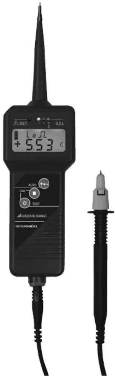
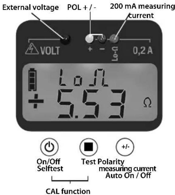
BEDs +/- for indication of polarity
ED for Lo- -mode, measurement current 200 mA
BED Volt warning of external voltage
Push-button polarity change,
retrieve measurement value,
operating mode
Push-button mea
ing, zero balancing.
Push-buttonOn/Offselves-test,zerobalancing
9ocket for measuring line
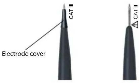
1Measuring line
19afety cap with snap lock
12est electrode of measuring line
Symbols on the device

Attention! Observe user instructions!

Exmarking:
Approved for Ex areas in accordance with ATEX
This device has to be disposed of according to the applicable regulations and laws (for Europe:WEEE 2012/19/EU).
Please contact service@gossenmetrawatt.com, in regard to the return of old devices.
1. Applications
The METRAOHM 413 is a digital displaying measuring instrument for the detection of low impedance from 10m up to 2000k
The METRAOHM 413 may only be used for power systems with an operating voltage of maximum 400V .
You can quickly and reliably inspect extensive protective conductor connections, grounding installations and equipotential bonding conductors as well as screening equipment and lightning arresters with the METRAOHM 413. A measurement current of 200mA and the automatic registration of values assure reliable measurement results. By use of any measurement lines resistance is measured between reference earth (e.g. equipotential bonding strip) and other test points.
1.1 Intended use
This device is intended for use in applications as described in the operating instructions only. Thus, it is imperative to observe the notes on safety and the technical data in conjunction with the ambient conditions.
Any other form of usage is not permitted and can lead to accidents or destruction of the unit.
Any misuse will result in the forfeiture of all guarantee and warranty claims.
2. Safety
You have selected a measuring instrument which provides a high level of safety. It meets requirements in accordance with EN/IEC 61557-1+4 (VDE 0413 part 1+4) and EN/IEC 61010.
In order to assure safe and proper use, it is imperative that you read these operating instructions thoroughly and completely before placing your instrument into service. All points included in these operating instructions must be followed carefully when using the instrument.
Please observe the following safety precautions:
The METRAOHM 413 may only be used for power systems with an operating voltage of maximum 400V
In conformity with standard DIN EN 61010-031, measurements in environments according to measurement category III may only be performed with the safety cap applied to the test probe of the measurement cable.
Measurements may only be taken at voltage-free system components.
Use the contact-protected plug (IP 2x with shrouded contacts) for the socket of the METRAOHM 413, when you test at measuring points where voltages may occur.
If the instrument comes into contact with a voltage of over 15V in its switched-on condition, an acoustic, as well as an optical warning, is generated (see 4.5). No measurements may be made at this conductor until it is made voltage-free.
The measuring instrument may only be dismantled by authorised personnel.
Before using the device check the housing and connecting line for visible damage. If damage is visible the earth resistance tester may not be placed into operation. In case of strong dirt contamination, the METRAOHM 413 must be cleaned before use.
The instrument has to be stored in a clean and dry environment.
3. Putting into operation
3.1 Battery
We have already inserted a 9 V battery IEC 6LR61 or IEC 6LF22. Your device is ready for operation. Before initial start-up, or after a lengthy period of storage, observe the instructions in section 5.
3.2 Testing correct display and function (self-test) Step 1 - Test of the display
Test electrodes must not come into contact with each other during self-test.
Press and hold button. All display segments light up, 4 LEDs flash as well as a buzzer sound can be heard. Release button ^+ Rdy" is indicated on the display.
The indication ^+ Rdy" signalizes readiness for measurement.
Note: When the display shows the error message "FUSE Err" after self test step 1 the fuse is defect (see section 7). If an empty battery symbol occurs on the display during the standby indication "+"Rdy", the battery needs to be exchanged (see section 5.).
Switch off the tester by pressing button
Step 2 - Checking the line / function
Connect the test lines with the socket and short-circuit them with the test electrode.
Press button and then the button at the same time. The zero balance will be performed. The display shows "CAL". After expiration of time the value "0,00 ... 0,04 Ω" is indicated on the display.
Through this, the overall functions have been tested.
Attention!
If one of the displays fails during the self-test - even if only partial failure occurs - (step 1) or if the instrument does not indicate a function standby (step 2), the earth resistance tester may not be placed into operation!
4. Measuring and testing
4.1 General information
Pushbutton functions:

ch-on/-off, self-test (3.)
balance (4.3)

suring (4.4)
balance (4.3)

rity reversal (4.4.1)
matic mode (4.4.2)

up measured values (4.4.2).
4.2 Measurement setup
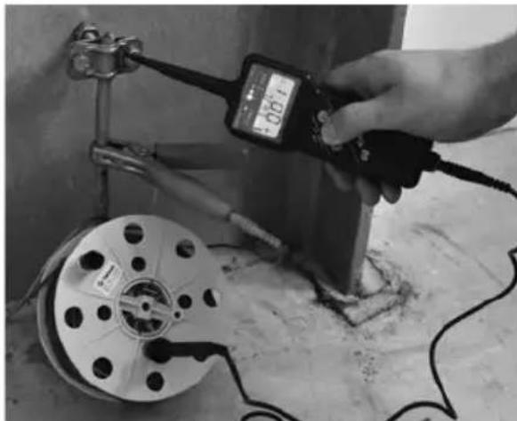
Any measurement line (up to approx. 3.5 can be used between the reference earth (e.g. equipotential bonding conductor) and the METRAOHM 413, which can be adjusted as described in section 4.3. Measurement locations at distances over 100m can be reached. In environments with strong field influences the circuit line should be reeled off completely, so that inductive influences can be avoided.
Fix the measuring line to the reference earth while ensuring good electrical conductivity (remove any corrosion).
Connect the free end of measuring line to the lower socket of METRAOHM 413. When using the uncoiling reel, the included short measuring line must be plugged into the socket of the reel.
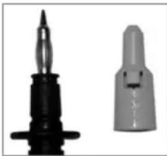
Only with mounted safety cap on the test electrode of the measuring line tests in CAT III enviroments are permitted in accordance with EN 61010-031.
The safety cap can be dismounted (e.g. for 4mm sockets) by lifting the snap lock with a sharp object.
4.3 Zero balancing
The METRAOHM 413 must be calibrated together with the entire measurement line before each measurement test series (see measurement setup 4.2). To take temperature changes into account, zero balancing is also necessary if the same measurement line is used again after a period of time. Balancing occurs automatically for all measuring ranges of 1 A ... 200mA
For balancing the device has to be switched off.
Contact the test electrode of the METRAOHM 413 to the reference earth and ensure safe contact
Press button and then the button at the same time. The zero balance will be performed.
The display shows "CAL". After expiration of time the value "0.00 ... 0.04 Ω" is indicated on the display.
Attention!
Maintain contact as long as "CAL" is displayed and the time expires.
If the message "Err" appears, zero balancing has failed and must be repeated. This error occurs if the test probe slips during balancing or if the measurement line is too high-resistive (>3.5) .
For test purposes we recommend that the first measurement always be made directly at the reference earth (see section 4.4). The result should be < 0.04 for both polaritys.
Note: Long coiled measuring lines may cause faulty measurments by their inductance. Resistance of the measurement line remains in storage until a new zero balance is performed. This value also remains in storage if the measuring instrument is switched off, or if the battery is replaced.
4.4 Measuring
Attention!
Measuring point must be free of voltage!
Button may only be pressed after establishing contact to the measuring point if there is an absence of voltage (see 4.5). Otherwise the device may be damaged.
If necessary, clean the measurement point from corrosion or paint.
Switch on the device with button (+) ( + Rdy and the green LED signalize that the device is ready for measurement).
Place the test electrode onto the measuring point vertically if possible and assure safe contact. If the red LED flashes and you hear an acoustic warning signal, an external voltage is present!
The test must be interrupted (see 4.5).
Short warning signals can be caused by inductive voltages or static charging which have no influence on the measurement.
Note: Direction of current flow is indicated in the display as "+" or "-". The displayed sign refers to the test probe.
4.4.1 Standard measurements 0 - 2 MΩ
Tests with 200mA in accordance with EN/IEC 61557-4 can only be performed for resistance < 10 and must be performed with manual polarity change.
Press button shortly to start the measurement. With measurement values < 10 the METRAOHM 413 automatically switches to Lo- mode and continues measuring with a measurement current of 200mA (tests comply with EN/IEC 61557-4).
The display shows the symbol Lo - ^ and the right LED briefly signalizes the 200 mA measurement current.
If the measurement value is out of measurement range (>1999k) the symbol "OL" (Overflow) appears on the display. The measurment result is displayed for approx. 3 s, after this the display changes to ^ + Rdy^
Change of polarity:
After measurement with positive polarity (see above): press button +I ("-Rdy" and green LED display readiness for measurement with different polarity). Perform measurements with negative polarity in the same way.
Large deviations between values are an indication for application of galvanic voltage. Repeat both measurements. If the results deviate from each other in a similar way than before, an average value between the "+" and "-" may be assumed.
4.4.2 Automatic measurement 0 - 10 Ω
Tests with automatic mode comply with EN/IEC 61557-4.
Automatic measurement is suitable only for resistance measurements till 10 Ω. They are performed with a measurement current of 200 mA
Hold button +/- pressed until POL +/- LEDs light up quickly and "AuTo" appears on the display. Automatic mode is now ready.
Shortly press button to start automatic measurement.
The pole changing is carried out automatically.
After measuring press button+ to switch between the measured resistance value with ^+ polarity and - polarity.
The device stores both measurement values until a new measurement is performed. To perform further measurements shortly press button
To get back to standard measurement press button (+/-) until POL +/- LEDs light up quickly and "AuTo" disappears from the display.
Error:
If the device does not display any measurement values an evaluation could be caused by following error:
The test probe slips
Heavily fluctuating impedances
Values outside of the measurement range
You have to repeat measuring. If repeated measurements do not provide clear results you need to perform a number of standard measurements with both polarities (see 4.4.1) and you must evaluate the measurement values on your own.
4.5 External voltage
If the METRAOHM 413 is switched on and comes into contact with a voltage (15 to 400V ) you hear an acoustic warning and the red LED flashes. For informational purposes the voltage value is displayed on the LCD.
In this case, measurement must not be performed.
Attention!
Button may only be pressed after establishing contact to the measuring point if there is an absence of voltage. Otherwise the device may be damaged.
Semiconductors protect the METRAOHM 413 up to 400V . With voltages >400V a fuse reacts that may only be exchanged by the manufacturer. The fuse is checked automatically during self-tests (see 3.2).
5. Battery
5.1 Battery indication
The latest battery status is symbolised by a three-stage battery indicator on the display.
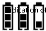
Replace the battery soon - few measurements possible (Battery symbol flashing: no further measurements admissible!)
Attention!
When the empty battery symbol flashes, then no more measurements can be performed and the battery has to be replaced immediately.
5.2 Battery change
The battery may only be replaced outside of Ex areas.
For replacing the battery the rear cover needs to be unscrewed.
You may only insert the following types of batteries: 9 V-block IEC 6LR61 / 6LF22 / 6LP314 (alkaline-manganese)
The connectors, jacks and contacts have to be kept clean.
Regularly make sure that the battery does not leak. In case it does you have to remove the electrolyte completely and insert a new battery.
In case of a longer storage period the METRAOHM 413 needs to be kept without battery at a dry and clean place with temperatures between -10^ and +70^
Note: Included in the scope of delivery is one battery. This battery is not to be re-charged. Attempting to recharge it may cause risk to personal safety and damage to the equipment. The battery may not be opened.
Depleted batteries have to be disposed of professionally. Please, return batteries to a local retailer or municipal recycling depot. Return is free of charge and required by law.
6. Maintenance
6.1 General information
The METRAOHM 413 is completely maintenance-free except for its energy source (see 5.) Nevertheless, in order to assure safe operation observe the following information: The METRAOHM 413 always has to be kept in a dry and clean condition. The plastic housing can be cleaned with a cloth dampened with isopropyl (alcohol) or soapy water. Do not use cleansing material that contains aceton or similar solvents.
6.2 Repeated inspection
We recommend a repeated inspection period no later than 6 years. Depending on operation conditions and frequency, a shorter inspection interval may be recommendable.
If the METRAOHM 413 is used as an inspection equipment, please note special repeat inspection time-limits. The serial number with the date of manufacturing (WWYYNN=Week Year Number) is imprinted on the backside of the device. Repeat inspection are offered by the manufacturer and indicated by the inspection plate.
7. Repair
Repair is only allowed by the manufacturer or explicitly authorised repair shops. In case of damage on the device or failure of the function test according to section 3.2 or for detailed inspection/calibration, please contact: www.gmci-service.com or send the device and a description of failure back to the manufacturer (address see page 1).
7.1 Cause of failure
The following failures can be determined by the user himself:
Broken fuse: LCD indication *FUSE Err" during self test (see 3.2)
At 230V socket the indicated voltage is only 110V When the measuring line is not connected and the push-button is pressed "OL" is not indicated. In these cases a damage by external voltage may be present. The tester may not be placed into operation and has to be sent for repair.
8. Limited warranty and limitation of liability
By continuous quality checks and production controls, state-of-the-art electronics and high quality materials we guarantee that the tester will be free from defects in material and workmanship for two years.
This warranty does not cover batteries, improper handling, improper use, opening the housing, improper storage or damage from accidents. No other warranties such as fitness for a particular purpose will be given. We are not liable for any indirect, incidental or consequential damage or loss arising from any cause whatsoever.
9. Technical data
Line tester and resistance measuring device METAROHM 413 in accordance with EN/IEC 61010-1 and EN/IEC 61557-4 (VDE 0413 part 4)
Measuring ranges
10Ω (Lo-Ω) resolution 0.01Ω
100,2000Ωresolution 0.1...1Ω
20,200,2000kΩresolution 0.01...1 kΩ
Accuracy
1.5% + / - 4 digit at 20^
Measurement current
10Ω (Lo-Ω)-range: 200 mA
100Ω-range: 20 mA
further range: 1 μA ... 20 mA
Open circuit voltage >4V
Adjustment of measuring line zero balance (CAL) up to 3.5
Digital display doublespaced LCD display, 3 1/2-digit, overflow display through OL screen backlighting
Voltage indication red LED and acoustic warning signal and indication of the value in Volt
External voltage detection 400 V
Overvoltage protection
CAT III 300 V / CAT II 600 V
in accordance with EN/IEC 61010-1
Operating temperature METRAOHM 413: -10°C ... +50°C
EMC requirement DIN-EN 61326
Power supply 9 V block IEC 6LR61 / 6LF22 / 6LP3146 alkaline-manganese multi-stage battery indicator automatic switch-off
Housing made of impact-proof ABS with unbreakable display cover
Protection category
IP 65, device usable in precipitation
Dimensions / Weight 60 × 230 × 40 ~mm / 180 ~g
10. Accessories
Measuring line and battery are included in the scope of delivery of the METRAOHM 413.
Quick user guide METRAOHM 413
This is a brief instruction. Observe the entire operating instruction of the METRAOHM 413 and follow all instruction contained therein.
Standard measurment up to 2 MΩ
Tests with 200mA according to EN/IEC 61557-4 only at resistance < 10 polarity change has to be performed manual.
Attention! First switch on the METRAOHM 413 and afterwards contact the measuring point with the test electrode. Button may not be pressed thereby, otherwise the METRAOHM 413 may be damaged by external voltages.
1. Measurement setup:
Connect the insulated 4 mm-connector of the measuring line to the socket of the METRAOHM 413.
Contact the reference earth with the test electrode of the measuring line (e.g. by clamp).
2. Zero balancing:
The tester has to be switched off for zero balancing.
Contact the test electrode of the METRAOHM 413 with the reference earth and ensure safe contact.
Press button and then button at the same time. Zero balancing will be performed.
3. Standard measurment:
Press button shortly to start the measurement.
4. Change of polarity:
Press button+1, the polarity is indicated by the green LEDs as well as the "+" or -Rdy" indication.
Automatic measurement up to 10 Ω
Tests with 200mA and automatic polarity change according to EN/IEC 61557-4.

Attention!
First switch on the METRAOHM 413 and afterwards contact the measuring point with the test electrode. Button may not be pressed thereby, otherwise the METRAOHM 413 can be damaged by external voltages.
1. Measurement setup:
Connect the insulated 4mm -connector of the the measuring line to the socket of the METRAOHM 413.
Contact the reference earth with the test electrode of the measuring line (e.g. by clamp).
2. Zero balancing:
The tester has to be switched off for zero balancing.
Contact the test electrode of the METRAOHM 413 to the reference earth and ensure safe contact.
Press button and then the button at the same time. The zero balance will be performed.
3. Select automatic measurement:
Hold button + / - pressed until POL + / - LEDs light up quickly and "AuTo" appears on the display.
4. Automatic measurement:
Shortly press button to start automatic measurement. The pole changing is carried out automatically.
5. Querying of stored measured values + / - :
Press button+ to switch between the measured resistance value with ^+ polarity and -polarity.
External voltage warning
Acoustic warning and red LED for interference voltage from 15V to 400V (voltage is displayed in V)
Continuity signal
An acoustic signal sounds for 2 seconds during measurement for resistance values < 2
11. Repair and Replacement Parts Service Calibration Center
and Rental Instrument Service
Repair is only allowed by the manufacturer or explicitly authorized repair shops.
In case of damage on the device or failure of the function test according to section 3.2 or for detailed inspection/calibration, please contact:
www.gmci-service.com
or send the device and a description of failure back to the following adress:
GMC-I Service GmbH
Service Center
90471 Numberg, Germany
Phone +49 911 817718-0
Fax +49 911 817718-253
E-Mail service@gossenmetrawatt.com
www.gmci-service.com
This address is only valid in Germany.
Please contact our representatives or subsidiaries for service in other countries.
12. Product Support
If required, please contact: