SecuLife HIT MD - Multimeter Gossen Metrawatt - Free user manual and instructions
Find the device manual for free SecuLife HIT MD Gossen Metrawatt in PDF.

| Product Type | Professional Digital Multimeter |
| Model | SecuLife HIT MD |
| Brand | Gossen Metrawatt |
| Dimensions (approx.) | 200 x 100 x 60 mm |
| Weight (approx.) | 500 g |
| Power Supply | 9V battery (PP3) or rechargeable battery option |
| Display | Digital LCD, 4-digit, with backlight |
| Measurement Functions | AC/DC voltage, AC/DC current, resistance, continuity, capacitance, frequency, temperature, diode test |
| True RMS | True RMS measurement for AC signals |
| Safety Rating | CAT III 600V, CAT IV 300V |
| Overvoltage Protection | Up to 600V |
| Data Hold | Yes |
| Auto Range | Yes |
| Min/Max Recording | Yes |
| Relative Mode | Yes |
| Auto Power Off | Yes, adjustable |
| Accessories Included | Test leads, temperature probe, carrying case, battery |
| Care and Cleaning | Wipe with dry cloth, avoid liquids; store in dry place |
| Safety Instructions | Observe maximum input ratings, use appropriate CAT rating, inspect leads before use |
| Spare Parts / Repairability | Replaceable fuse, battery; service by qualified personnel |
| General Information | Manual includes safety notes, specifications, and operating instructions |
Frequently Asked Questions - SecuLife HIT MD Gossen Metrawatt
User questions about SecuLife HIT MD Gossen Metrawatt
0 question about this device. Answer the ones you know or ask your own.
Ask a new question about this device
Download the instructions for your Multimeter in PDF format for free! Find your manual SecuLife HIT MD - Gossen Metrawatt and take your electronic device back in hand. On this page are published all the documents necessary for the use of your device. SecuLife HIT MD by Gossen Metrawatt.
USER MANUAL SecuLife HIT MD Gossen Metrawatt
Operating Instructions

GOSSEN METRAWATT
SECULIFE HITAM HITMD
METRAHIT X-TRA OUTDOOR TECH PRO BASE
TRMS Digital Multimeter
3-349-352-03
13/5.17
natural_image
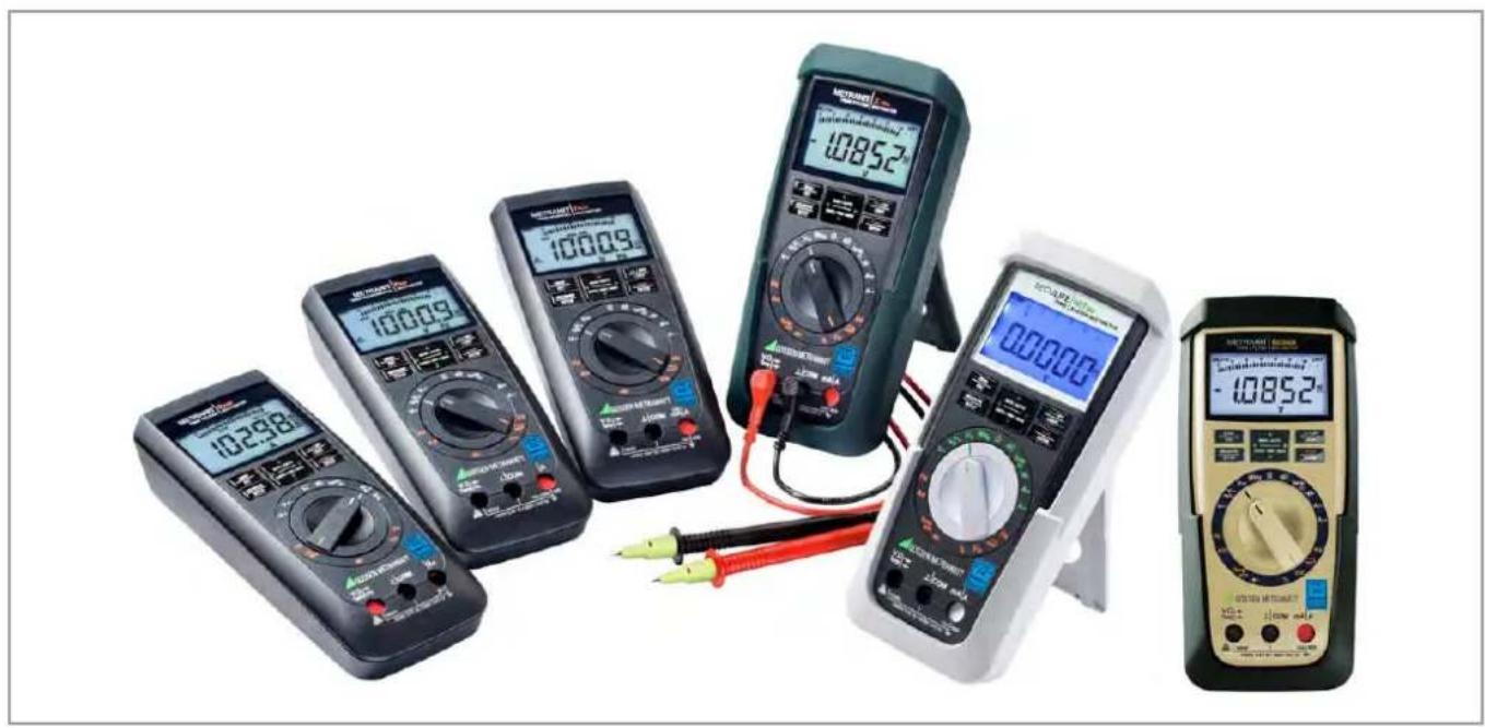
Product display of six different multimeters and analog meters, including digital and analog models with visible measurement ranges (no text or symbols on devices themselves)Standard Equipment Contact Persons
Standard Equipment
1 multimeter
1 measurement cable set
2 batteries
1 abbreviated operating instructions
– Detailed operating instructions for download from our website at www.gossenmetrawatt.com
1 DAkkS calibration certificate
| Function SECULIFE | HITAM/HITMD | METRAHIT X-TRA/ OUTDOOR | METRAHIT TECH | METRAHIT PRO | METRA HIT BASE |
| M687A/M687B | M240A/M2400 | M243A M242A | M241A | ||
| V AC / Hz TRMS (Ri ≥ 9 MΩ) | & 1kHz\F | & i 1kHz\A | & i kHz\Ie | & i kHz\B | r • I |
| V AC TRMS (Ri = 1 MΩ) | & 1kHz\F | & i 1kHz\IF | & i kHz\E | & i kHz\B | r — I |
| V AC+DC TRMS (Ri ≥ 9 MΩ) | • | • | • | • | • |
| V DC (≥ 9 MΩ) | • | • | • | • | • |
| ... 1 MHz 5 V AC ∥ | • | • | — | — | — |
| Duty cycle as % | • | • | — | — | — |
| Hz (V AC) | ... 100 kHz | ... 100 kHz | ... 100 kHz | ... 100 kHz | ... 100 kHz |
| Bandwidth V AC | 15 Hz ... 20 kHz | 15 Hz ... 20 kHz | 15 Hz ... 10 kHz | 15 Hz ... 10 kHz | 15 Hz ... 1 kHz |
| A AC / Hz TRMS | 100 μA1/10/100 mA1 A / 10 (16)A | 100 μA1/10/100 mA1 A / 10 (16)A | 10/100 mA1 A / 10 (16)A | 1 A / 10 (16)A | — |
| A AC+DC TRMS | — | ||||
| A DC | — | ||||
| Fuse | 10 A/1000 V | 10 A/1000 V | 10 A/1000 V | 10 A/1000 V | — |
| Transformation factor >C | — | — | • | — | • |
| A AC >C / Hz TRMS | — | — | mVAmA/A | — | mVARi = 1 MΩ |
| A AC+DC >C TRMS | — | — | mVAmA/A | — | mVARi = 1 MΩ |
| Function SECULIFE | HITAM/HITMD | METRAHIT X-TRA/ OUTDOOR | METRAHIT TECH | METRAHIT PRO | METRA HIT B ASE |
| M687A/M687B | M240A/M2400 | M243A M242A M241A | |||
| ADC ≥slant C | — | — | mV/A mA/A | — | mV/A RI = 1 M |
| Hz (A AC) | ... 30 kHz | ... 30 kHz | ... 30 kHz | ... 30 kHz | ... 30 kHz |
| Resistance | ● | ● | ● | ● | ● |
| Continuity [IMAGE] | ● | ● | ● | ● | ● |
| Dlode ... 5,1 V ➤I | ● | ● | ● | ● | ● |
| Temperature TC (K) | ● | ● | ● | ● | ● |
| Temperature RTD | ● | ● | — | — | — |
| Capacitance —II— | ● | ● | ● | — | — |
| MIN/MAX/data hold | ● | ● | ● | ● | ● |
| 4 MBit _4 memory1) | ● | ● | — | — | — |
| IR Interface | ● | ● | — | — | — |
| Power pack adapter socket | ● | ● | — | — | — |
| Protection | IP65 | X-TRA: IP52 OUTDOOR: IP65 | IP52 | IP52 | IP52 |
| Antimicrobial properties | ● / — | — | — | — | — |
| Measuring category | 600 V CAT III 300 V CAT IV | 1000 V CAT III 600 V CAT IV | 1000 V CAT III 600 V CAT IV | 1000 V CAT III 600 V CAT IV | 1000 V CAT III 600 V CAT IV |
| Rubber holster | ● | ● | — | — | — |
| Measurement cable set | KS17-2AMB/KS17-2 | KS17-2 KS17-2 KS17-2 | KS17-2 | KS17-2 | |
| DAkkS callbr. certificate | ● | ● | ● | ● | ● |
| Hygiene Expertise | — / ● | — | — | — | — |
1) For 15,400 measured values, sampling rate adjustable from 0.1 second to 9 hours
Accessories (sensors, plug inserts, adapters, consumable materials)
The accessories available for your instrument are checked for compliance with currently valid safety regulations at regular intervals, and are expanded as required for new applications. Currently up-to-date accessories which are suitable for your measuring instrument are listed at the following web address along with photo, order number, description and, depending upon the scope of the respective accessory, data sheet and operating instructions: www.gossenmetrawatt.com
See also chapter 10 on page 66.
Product Support
Technical Queries
(use, operation, software registration)
If required please contact:
Product Support Hotline
Phone: +49 911 8602-0
Fax: +49 911 8602-709
e-mail support@gossenmetrawatt.com
Software Enabling for METRAwin 10
Standard Equipment Contact Persons
Recalibration Service
We calibrate and recalibrate all instruments supplied by GMC-I Messtechnik GmbH, as well as other manufacturers, at our service center, for example after one year within the framework of your test equipment monitoring program, as well as prior to use etc.
Repair and Replacement Parts Service
Calibration Laboratory\* and Rental Instrument Service
If required please contact:
GMC-I Service GmbH
Service Center
Thomas-Mann-Str. 20
90471 Nürnberg, Germany
Phone: +49 911 817718-0
Fax: +49 911 817718-253
e-mail: service@gossenmetrawatt.com
www.gmci-service.com
This address is only valid in Germany. Please contact our representatives or subsidiaries for service in other countries.
DAkkS Calibration laboratory for measured electrical quantities, D-K-15080-01-01, accredited in accordance with DIN EN ISO/IEC 17025
Accredited quantities: direct voltage, direct current value, direct current resistance, alternating voltage, alternating current value, AC active power, AC apparent power, DC power, capacitance, frequency, temperature
Competent Partner
GMC-I Messtechnik GmbH is certified in accordance with DIN EN ISO 9001.
Our DAkkS calibration laboratory is accredited by the Deutsche Akkreditierungsstelle GmbH (National accreditation body for the Federal Republic of Germany) in accordance with DIN EN ISO/IEC 17025 under registration number D-K-15080-01-01.
We offer a complete range of expertise in the field of metrology: from test reports and factory calibration certificates, right on up to DAkkS calibration certificates.
Our spectrum of offerings is rounded out with free test equipment management.
As a full service calibration laboratory, we can calibrate instruments from other manufacturers as well.
Contact Persons
Table of Contents
Contents Page Contents Page
1 Safety Features and Precautions 8
1.1 Use for Intended Purpose ....10
1.2 Meanings of Danger Symbols ....10
1.3 Meanings of Acoustic Warning Signals 10
2 Operating Overview – Connections, Keys, Rotary Switch, Symbols . 12
3 Initial Start-Up 16
3.1 Inserting Batteries or Rechargeable Batteries 16
3.2 Activation ......16
3.3 Setting the Operating Parameters ......16
3.4 Switching the Instrument Off 17
4 Control Functions ...... 18
4.1 Selecting Measuring Functions and Measuring Ranges .....18
4.1.1 Automatic Range Selection 18
4.1.2 Manual Measuring Range Selection ....18
4.1.3 Quick Measurements .... 19
4.2 Zero Offset / Relative Measurements .....19
4.3 Display (LCD) 20
4.3.1 Digital Display 20
4.3.2 Analog Display 20
4.4 Measured Value Storage: DATA (auto-hold / compare) .....21
4.4.1 Saving Minimum and Maximum Values - MIN/MAX Function .....22
4.5 Measurement Data Recording (METRA HIT X-TRA/OUTDOOR and SECULIFE HIT AM/MD only) 23
5 Measurements 26
5.1 Voltage Measurement 26
5.1.1 Direct and Pulsating Voltage Measurement, V DC and V (DC+AC) .....27
5.1.2 Alternating Voltage Measurement with 1 M _W Load Resistance and Frequency Measurement with Selectable Low-Pass Filter (METRAHIT X-TRA/OUTDOOR/TECH/PRO/SECULIFEHITAM/MD only) .....28
5.1.3 Alternating Voltage and Frequency Measurement V AC and Hz with Selectable Low-Pass Filter (METRAHIT X-TRA/OUTDOOR/TECH/PRO/SECULIFEHITAM/MD only) .....30
5.1.4 Frequency and Duty Cycle Measurements (METRAHIT X-TRA/OUTDOOR/SECULIFEHITAM/MD only) 32
5.2 Resistance Measurement, Ω 33
5.3 Continuity Test ....34
5.4 Diode Testing with a Constant Current of 1 mA .....35
5.5 Temperature Measurement 36
5.5.1 Measurement with Thermocouples, Temp TC 36
5.5.2 Measurement with Resistance Thermometers (METRAHIT X-TRA/OUTDOOR/SECULIFEHITAM/MD only) ....37
5.6 Capacitance Measurement (METRAHIT X-TRA/OUTDOOR/SECULIFEHITAM/MD and METRAHIT TECH only) 38
5.7 Current Measurement 39
5.7.1 Direct and Pulsating Current Measurement, Direct Connection, A DC and A (DC+AC) (METRAHIT X-TRA/OUTDOOR/TECH/PRO only) 40
5.7.2 Alternating Current and Frequency Measurement, Direct Connection, A AC and Hz (METRAHIT X-TRA/OUTDOOR/TECH/PRO/SECULIFEHITAM/MD only) .....41
5.7.3 Direct and Pulsating Current Measurement with Clip-On Current Sensor, A DC and A (DC+AC) (METRAHIT TECH and METRAHIT BASE only) ..... 42
Contents Page Contents Page
5.7.4 Alternating Current Measurement with Clip-On Current Sensor, A AC and Hz (METRAHIT TECH and METRAHIT BASE only) ..... 43
5.7.5 Direct, Pulsating and Current Measurement with Clip-On Current Transformer A DC, A (DC+AC), A AC and Hz (METRAHIT TECH only). 44
6 Device and Measuring Parameters ....46
6.1 Paths to the Various Parameters 47
6.2 List of All Parameters 47
6.3 Querying Parameters – InFo Menu (as moving letters) 48
6.4 Entering Parameters - SETUP Menu 48
6.5 Default Settings 50
7 Interface Operation (METRAHIT X-TRA/OUTDOOR/SECULIFEHIT AM/MD only) 52
7.1 Activating the Interface 52
7.2 Configuring Interface Parameters 53
8 Technical Data ....54
9 Maintenance and Calibration 62
9.1 Displays – Error Messages 62
9.2 Batteries 62
9.3 Fuse (METRAHIT X-TRA/OUTDOOR, METRAHIT TECH, METRAHIT PRO and SECULIFEHITAM/MD only) 63
9.4 Housing Maintenance 64
9.5 Return and Environmentally Sound Disposal 64
9.6 Recalibration 65
9.7 Manufacturer's Guarantee 65
10 Accessories ....66
10.1 General 66
10.2 Technical Data for Measurement Cables 66
10.3 NA X-TRA Power Pack (not included) 66
10.4 Interface Accessories for METRAHIT X-TRA/OUTDOOR and SECULIFEHITAM/MD (not included) 67
11 Index 68
Safety Precautions
1 Safety Features and Precautions
You have selected an instrument which provides you with a high level of safety.
This instrument fulfills the requirements of applicable EU guidelines and national regulations. We confirm this with the CE marking. The relevant declaration of conformity can be obtained from GMC-I Messtechnik GmbH.
The TRMS digital multimeter has been manufactured and tested in accordance with the following safety regulations: IEC 61010-1:2010/DIN EN 61010-1:2011/VDE 0411-1:2011.
When used for its intended purpose (see page 10), safety of the operator, as well as that of the instrument, is assured. Their safety is however not guaranteed, if the instrument is used improperly or handled carelessly.
In order to maintain flawless technical safety conditions, and to assure safe use, it is imperative that you read the operating instructions thoroughly and carefully before placing your instrument into service, and that you follow all instructions contained therein.
The multimeter is equipped with an automatic socket blocking mechanism for your safety, and in order to safeguard your instrument. This mechanism is linked to the rotary switch and only allows access to those jacks which are actually required for the selected function. It also prevents the user from turning the rotary switch to impermissible functions after the measurement cables have already been plugged in.
Measuring Categories and their Significance per IEC 61010-1
| CAT Definition | |
| I | Measurements in electrical circuitswhich are not directly connected to the mains:for example electrical systems in motor vehicles and aircraft, batteries etc. |
| II | Measurements in electrical circuitswhich are electrically connected to the low-voltage mains:with plugs, e.g. at home, in the office or laboratory etc. |
| III | Measurements in building installations:stationary power consumers, distributor terminals, devices connected permanently to the distributor |
| IV | Measurements at power sources for low-voltage installations:meters, mains terminals, primary overvoltage protection devices |
The measuring category and the maximum rated voltage which are printed on the device apply to your measuring instrument, for example 1000 V CAT III.
For the application of measuring cables see page 66.
Observe the following safety precautions:
- The multimeter may not be used in potentially explosive atmospheres.
- The multimeter may only be operated by persons who are capable of recognizing contact hazards and taking the appropriate safety precautions. Contact hazards according to standard exist anywhere, where voltages of greater than 33 V RMS or 70 V DC may occur. Avoid working alone when taking measurements which involve contact hazards. Be certain that a second person is present.
- Maximum allowable voltage between the voltage measuring terminals, and between all connections and earth is 1000 V for measuring category III, or 600 V for measuring category IV. Exception SECULIFE HITAM/HITMD: 600 V CAT III and 300 V CAT IV.
- Be prepared for the occurrence of unexpected voltages at devices under test (e.g. defective devices). For example, capacitors may be dangerously charged.
- Make certain that the measurement cables are in flawless condition, e.g. no damage to insulation, no interruptions in cables or plugs etc.
- No measurements may be made with this instrument in electrical circuits with corona discharge (high-voltage).
- Special care is required when measurements are made in HF electrical circuits. Dangerous pulsating voltages may be present.
- Measurements under moist ambient conditions are not permitted.
- Be absolutely certain that the measuring ranges are not overloaded beyond their allowable capacities. Limit values are included in chapter 8, "Technical Data", in the table entitled "Measuring Functions and Measuring Ranges" in the "Overload Capacity" column.
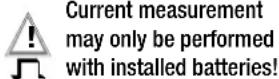
- The multimeter may only be operated with installed batteries or rechargeable batteries. Dangerous currents and voltages are otherwise not indicated, and the instrument may be damaged.
- The instrument may not be operated if the fuse cover or the battery compartment lid has been removed, or if its housing is open.
- The input for the current measuring range is equipped with a fuse link (exception: METRAHIT BASE). Maximum permissible voltage for the measuring circuit (= rated voltage of the fuse) is 1000 V AC/DC. Use specified fuses only (see page 59)! The fuse must have a breaking capacity of at least 30 kA.
Opening of Equipment / Repair
The equipment may be opened only by authorized service personnel to ensure the safe and correct operation of the equipment and to keep the warranty valid.
Even original spare parts may be installed only by authorized service personnel.
In case the equipment was opened by unauthorized personnel, no warranty regarding personal safety, measurement accuracy, conformity with applicable safety measures or any consequential damage is granted by the manufacturer.
Repair and Parts Replacement
When the instrument is opened, voltage conducting parts may be exposed. The instrument must be disconnected from the measuring circuit before the performance of repairs or the replacement of parts. If repair of a live open instrument is required, it may only be carried out by trained personnel who are familiar with the dangers involved.
Defects and Extraordinary Strains
If it may be assumed that the instrument can no longer be operated safely, it must be removed from service and secured against unintentional use.
Safe operation can no longer be relied upon:
- If the device demonstrates visible damage
- If the instrument no longer functions, or if malfunctioning occurs
- After long periods of storage under unfavorable conditions, e.g. humidity, dust or extreme temperature (see “Ambient Conditions” on page 60)
Safety Precautions
1.1 Use for Intended Purpose
- The respective multimeter is a portable device which can be held in the hand during the performance of measurements.
- Only those types of measurements described in chapter 5 may be performed with the measuring instrument.
- The measuring instrument, including measurement cables and plug-on test probes, may only be utilized within the specified measuring category (see page 59 and the table on page 8 regarding significance).
- Overload limits may not be exceeded. See technical data on page 54 for overload values and overload limits.
- Measurements may only be performed under the specified ambient conditions. See page 60 regarding operating temperature range and relative humidity.
- The measuring instrument may only be used in accordance with the specified degree of protection (IP code) (see page 60).
1.2 Meanings of Danger Symbols

Warning concerning a point of danger (attention: observe documentation!)

Warning concerning dangerous voltage at the measurement input: U > 55 V AC or U > 70 V DC
1.3 Meanings of Acoustic Warning Signals

Voltage warning: >1000V (intermittent acoustic signal)

Current warning: > 10 A (intermittent acoustic signal)
Current warning: > 16 A (continuous acoustic signal)
Safety Precautions
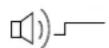
2 Operating Overview – Connections, Keys, Rotary Switch, Symbols
* METRAHIT BASE: Current measurement by means of clip-on current sensor with voltage output only
1 Display (LCD) (see page 13 for significance of symbols)
2 MAN / AUTO shift key for manual/automatic measuring range selection
△ Increase parameter values
Operating mode menu: Select individual menu entries against direction of flow
3 ON / OFF | LIGHT key for switching device and display illumination on and off
4 FUNC | ENTER multifunction key
Operating mode menu: Acknowledge entry (ENTER)
5 ▷ Increase measuring range or move decimal point to the right (MAN function)
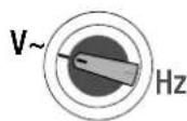
6 Rotary switch for measuring functions, (see page 15 for significance of symbols)
7 DAkkS calibration mark
8 Connector socket for ground
9 Connector socket for current measurement with automatic blocking
10 Connector socket for voltage, resistance, temperature, diode and capacitance measurement (METRAHIT X-TRA/OUTDOOR, METRAHIT TECH and SECULIFEHIT AM/MD only) with automatic blocking
11 DATA / MIN / MAX
Key for freezing, comparing and deleting measured value, and for Min/Max
Decrease values
Operating mode menu: Select individual menu entries in direction of flow
12 MEASURE I SETUP
Key for switching back and forth between measuring and menu function
13 ZERO | ESC
Key for zero balancing
Operating mode menu: Exit current menu level and
return to a higher level,
exit parameters configuration
without saving data
14 △ Decrease measuring range or move decimal point to the left (MAN function)
15 Connector for power pack (METRAHIT X-TRA/OUTDOOR & HITAM/MD only)
16 Infrared interface (METRAHIT X-TRA/OUTDOOR & SECULIFEHITAM/MD only)
Symbols Used in the Digital Display 1 Battery level indicator
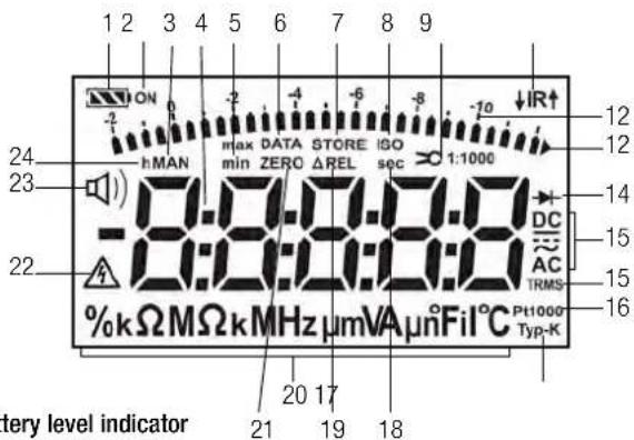
Battery level indicator

Battery full

Battery OK

Battery weak

Battery (almost) dead, U < 1.8 V
Interface indicator

METRAHIT X-TRA/OUTDOOR and SECULIFEHITAM/MD:
Active data transmission ↓ to / ↑ from multimeter

IR interface in stand-by mode (ready to receive starting commands)
2 ON: continuous operation (automatic shutdown deactivated)
3 MAN: manual measuring range selection is active
4 Digital display with decimal point and polarity display
5 max/min: Min/Max value storage
6 DATA: display memory, "freeze" measured value
7 STORE: memory mode active, with METRAHIT X-TRA/OUTDOOR and SECULIFEHIT AM/MD only
8 ISO: no function here
9 Transformation factor (current clip factor), with METRAHIT BASE and METRAHIT TECH only
10 IR: infrared interface display, with METRAHIT X-TRA/OUTDOOR and SECULIFE HITAM/MD only
11 Scale for analog display
12 Pointer for analog display (bar graph - pointer) depending upon setting in SEE menu for the R.0 SP parameter Triangle appears: indicates overranging
13 Diode measurement selected
14 Selected type of current
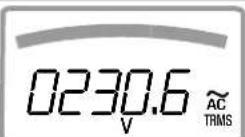
15 TRMS measurement
16 Pt100(0): selected platinum resistance thermometer with automatic recognition of Pt100/Pt1000, with METRAHIT X-TRA/OUTDOOR and SECULIFEHITAM/MD only
17 Type K: temperature measurement with type K (NiCr-Ni) thermocouple
18 sec (seconds): unit of time
19 ΔREL: relative measurement with reference to offset
20 Unit of measure
21 ZERO: zero balancing active
22 Warning regarding dangerous voltage: U > 55 V AC or U > 70 V DC
23 Continuity test with acoustic signal is active
24 h (hours): unit of time
Symbols of Rotary Switch Positions
| Switch | FUNC | Display Measuring Function | METRAHIT X-TRA OUTDOOR SECULIFEHIT AM/MD | METRAHIT TECH | METRAHIT PRO | METRAHIT BASE | |
| V~ | 0/4 | V~ AC TRMS | Alternating voltage, TRMS AC, full bandwidth | ● | ● | ● | ● |
| Hz (V) | 1 | Hz ~ AC | Voltage frequency, full bandwidth | ● | ● | ● | ● |
| V~ 1kHz\ | 2 | V Fil ~ AC TRMS | Alternating voltage, TRMS AC, with low-pass (1 kHz) | ● | ● | ● | — |
| Hz (V) 1kHz\ | 3 | Hz Fil ~ AC | Voltage frequency, with low-pass (1 kHz) | ● | ● | ● | — |
| V~ 1 MΩ | 0/4 | V~ AC TRMS | Alternating voltage, TRMS AC, full bandwidth, input 1 MΩ | ● | ● | ● | — |
| V~ 1kHz\ | 1 | V Fil ~ AC TRMS | Alternating voltage, TRMS AC, up to 1 kHz, input 1 MΩ | ● | ● | ● | — |
| Hz (V) 1kHz\ | 2 | Hz Fil ~ AC | Voltage frequency, up to 1 kHz, input 1 MΩ | ● | ● | ● | — |
| Hz (V) 1 MΩ | 3 | Hz ~ AC | Voltage frequency, full bandwidth, input 1 MΩ | ● | ● | ● | — |
| V== | 0/2 | V== DC | Direct voltage | ● | ● | ● | ● |
| V≈ | 1 | V≈ DC AC TRMS | Pulsating voltage, TRMS ( V_ACDC = _AC + V_DC ) | ● | ● | ● | ● |
| MHz | 0/2 | MHz | (High) frequency @ 5 V~ | ● | — | — | — |
| % | 1 | % | Duty cycle @ 5 V~ | ● | — | — | — |
| Ω | — | Ω | (Direct current) resistance | ● | ● | ● | ● |
| 0/2 | Continuity testing Ω with acoustic signal | ● | ● | ● | ● | ||
| 1 | Diode voltage | ● | ● | ● | ● | ||
| Temp TC | 0/2 | °C Typ-K | Temperature thermocouple Type K | ● | ● | ● | ● |
| Temp RTD | 1 | °C Pt100/1000 | Temperature with resistance thermometer Pt100/Pt1000 | ● | — | — | — |
| — | nF | Capacitance | ● | ● | — | — | |
| A== | 0/2 | A== DC | Direct current value | ● | ● | ● | — |
| A≈ | 1 | A≈ DC AC TRMS | Pulsating current value, TRMS AC DC | ● | ● | ● | — |
| A~ | 0/2 | A~ AC TRMS | Alternating current value, TRMS AC | ● | ● | ● | — |
| Hz (A) | 1 | Hz ~ AC | Current frequency | ● | ● | ● | — |
| × A== | 0/2 A | =DC Direct current value with AC DC clip-on current sensor 1 V:1/10/100/1000 A | — | ● | — | ● | |
| × A ≈ | 1 A | DC AC TRMS × | Pulsating current value, TRMS, with AC DC clip-on current sensor, see above | — | ● | — | |
| × A ~ | 0/2 A~ AC TRMS × | Alternating current strength, IRMS, with clip-on current sensor, see above | — | ● | — | ||
| Hz (×CA) | 1 | Hz ~ AC × | Current frequency | — | ● | — | |
Operating Overview – Connections, Keys, Rotary Switch, Symbols
User Interface Symbols in the Following Chapters
▷ ... ▷ Scroll through main menu
∇ ... ∇ Scroll through sub-menu
◀ ▷ Select decimal point
△▽ Increase/decrease value
b, NESub-menu/parameter (7-segment font)
InFoMain menu (7-segment font, boldface)
Symbols on the Device

Warning concerning a point of danger (attention: observe documentation!)

Ground
CAT III / IV Measuring category III or IV device, see also "Measuring Categories and their Significance per IEC 61010-1" on page 8

Continuous, doubled or reinforced insulation

Indicates EC conformity

Position of the infrared interface, window on the top of the instrument (METRAHIT X-TRA/OUTDOOR and SECULIFEHITAM/MD only)
Position of the power pack connector socket, see also chapter 3.1 (METRAHIT X-TRA/OUTDOOR and SECULIFEHITAM/MD only)

Fuse for current measuring ranges, see chapter 9.3 (not METRAHIT BASE)

The device may not be disposed of with the trash. Further information regarding the WEEE mark can be accessed on the Internet at www.gossenmetrawatt.com under the search term WEEE (see also chapter 9.5).
Calibration seal (blue seal):
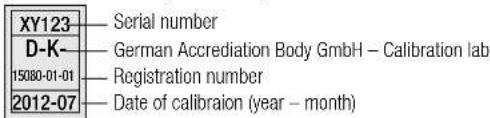
see also "Recalibration" on page 65.
Initial Start-Up – Setup
3 Initial Start-Up
3.1 Inserting Batteries or Rechargeable Batteries
Be certain to refer to chapter 9.2 regarding correct battery installation.
Momentary battery voltage can be queried in the Info menu (see chapter 6.3).

Attention!
Disconnect the instrument from the measuring circuit before opening the battery compartment lid in order to replace the batteries.
Operation with the Power Pack
(accessory for METRAHIT X-TRA and SECULIFE HITAM/MD, not included, see chapter 10.3)
Installed batteries are disconnected electronically if the NA X-TRA power pack is used, and need not be removed from the instrument.
If rechargeable batteries are used, they must be recharged externally.
If the external power supply is switched off, the device is automatically switched to battery operation without interruption.
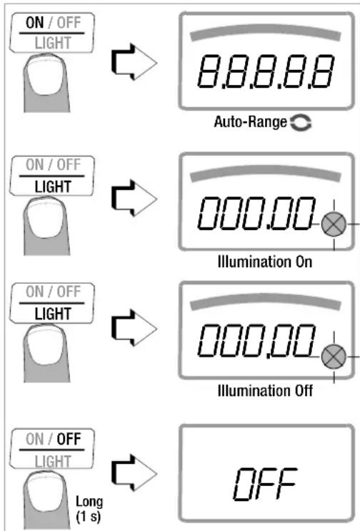
3.2 Activation
Switching the Instrument On Manually
→ Press the ON / OFF | LIGHT key until the display appears.
Power-up is acknowledged with a brief acoustic signal. As long as the key is held depressed, all of the segments at the liquid crystal display (LCD) are illuminated.
The LCD is depicted on page 13.
The instrument is ready for use as soon as the key is released.
Display Illumination
After the instrument has been switched on, background illumination can be activated by briefly pressing the ON / OFF | LIGHT key. Illumination is switched back off by once again pressing the same key, or automatically after approximately 1 minute.
Switching the Instrument On via PC (METRAHIT X-TRA/OUTDOOR/AM/MD only)
The multimeter is switched on after transmission of a data block from the PC, assuming the ",rStb" has been set to ",ron" (see chapter 6.4).
However, we recommend using the power saving mode: ", roFF".

Note
Electrical discharge and high frequency interference may cause incorrect displays to appear, and may disable the measuring sequence.
Disconnect the device from the measuring circuit. Switch the instrument off and back on again in order to reset. If the problem persists, briefly dislodge the battery from the connector contacts (see also chapter 9.2).
3.3 Setting the Operating Parameters
Setting Time and Date
See the “E, NE” and “DRE” parameter in chapter 6.4.
Display Modes for the Analog Display
Selection can be made from two different display modes (see "R.d, 5P" parameter in chapter 6.4).
Display Modes for the Digital Display
Selection can be made from two different display modes (see "0.d, 5P" parameter in chapter 6.4).
3.4 Switching the Instrument Off
Switching the Instrument Off Manually
Press the ON / OFF | LIGHT key until OFF appears at the display. Shutdown is acknowledged with a brief acoustic signal.
Automatic Shutdown
The instrument is switched off automatically if the measured value remains unchanged for a long period of time (maximum measured value fluctuation of approx. 0.8% of the measuring range per minute, or 1 °C or 1 °F per minute), and if none of the keys or the rotary switch have been activated before a selected period of time in minutes has elapsed (see "RPFF" parameter on page 49.)
Shutdown is acknowledged with a brief acoustic signal.
Exceptions include:
Transmission and memory mode operation, continuous operation and whenever a dangerous voltage is applied to the input (U > 55 V AC or U > 70 V DC).
Disabling Automatic Shutdown
The instrument can be set to continuous operation.
Simultaneously press the this end.
ON / OFF and keys to LIGHT
FUNC ENTER
The “Continuous On” function is indicated at by means of the ON display to the right of the battery symbol.
The “Continuous On” setting can only be cancelled by changing the respective parameter, and not by switching the instrument off (see “RPoff” on page 49).
4 Control Functions
4.1 Selecting Measuring Functions and Measuring Ranges
The rotary switch is linked to the automatic socket blocking mechanism, which only allows access to two connector jacks for each function. Be certain to remove the appropriate plug from its respective jack before switching to and from the "A" functions. The socket blocking mechanism prevents the user from inadvertently turning the selector switch to impermissible functions after the measurement cables have been plugged in to the instrument.
4.1.1 Automatic Range Selection
The multimeter is equipped with auto-ranging for all measuring functions, except for temperature measurement, diode and continuity testing, and the MHz measuring function. Auto-ranging is active as soon as the instrument is switched on. The instrument automatically selects the measuring range which allows for highest possible resolution of the applied quantity. When the instrument is switched to frequency measurement, the previously selected voltage measuring range remains active.
The Auto-Ranging Function
The multimeter is switched automatically to the next higher range at ±(1999d+1d1200d) , and to the next lower range at ±(1100d-1d990d) .
Exception, capacitance measurement:
The multimeter is switched automatically to the next higher range at ±(199d+1d20d) , and to the next lower range at ±(10d-1d099d) .
4.1.2 Manual Measuring Range Selection
Auto-ranging can be deactivated and measuring ranges can be selected manually in accordance with the following table by pressing the MAN / AUTO button.
The desired measuring range can then be selected with the ◀ or ▷ scroll key.
The instrument is automatically returned to range selection when the MAN / AUTO key is pressed, the rotary switch is activated or the instrument is switched off and back on again.
Overview: Auto-Ranging and Manual Range Selection
| Function Display | ||
| MAN / AUTO | Manual mode active: utilized measuring range is fixed | MAN |
| ◀ or ▷ | Range switching sequence for: V: 100 mV* ↔1 V ↔ 10 V ↔ 100 V ↔ 1000 V Hz: 100 Hz ↔ 1 kHz ↔ 10 kHz ↔ 100 kHz Ω: 100 Ω ↔1 kΩ ↔ 10 kΩ ↔ 100 kΩ ↔1 MΩ ↔ 10 MΩ ↔40 MΩ A: METRAHIT X- TRA/OUTDOOR and SECULIFE HITAM/MD: 100 μA ↔ 1 mA ↔ 10 mA ↔ 100 mA ↔ 1 A ↔ 10 A (16 A) METRAHIT TECH: 10 mA ↔ 100 mA ↔ 1 A ↔ 10 A (16 A) METRAHIT PRO: 1A ↔ 10 A (16 A) A R: METRAHIT BASE and METRAHIT TECH: see chapter 5.7.3 ff F: METRAHIT X- TRA/OUTDOOR, SECULIFE HITAM/MD and METRAHIT TECH: 10 nF ↔ 100 nF ↔ 1 μF ↔ 10 μF ↔ 100 μF ↔ 1000 μF | MAN |
| MAN / AUTO | Return to automatic measuring range selection — |
* Via manual measuring range selection only
4.1.3 Quick Measurements
Measurements performed using a suitable fixed measuring range are executed more quickly than those which utilize automatic range selection. Quick measurement is made possible with the following two functions:
- Manual measuring range selection, i.e. selection of the measuring range with the best resolution (see chapter 4.1.2).
or - With the DATA function (see chapter 4.4). In this way, the appropriate measuring range is selected automatically after the first measurement and the second measurement is executed more quickly.
The selected measuring range remains active for the subsequent series of measurements with these two functions.
4.2 Zero Offset / Relative Measurements
Depending upon deviation from the zero point, zero balancing or a reference value for relative measurements can be stored to memory:
| Deviation from zero– With short-circuited measurement cables for V, Ω, A– With open input for capacitance unit of measure F | Display |
| 0 to 200 digits ZERO ΔREL | |
| >200 to 5000 digits ΔREL |
The applicable reference or correction value is deducted individually for the respective measuring function as an offset from all subsequent measurements, and remains in memory until deleted, or until the multimeter is switched off.
Zero balancing and reference value adjustment can be used for auto-ranging, as well as for manual measuring range selection.
Zero Balancing
Plug the measurement cables into the instrument and connect the free ends to each other, except for capacitance measurement in which case the ends of the cables are not connected to each other.
Briefly press the ZERO | ESC key.
The instrument acknowledges zero balancing with an acoustic signal, and the "ZERO REL" symbol appears at the LCD. The value measured at the moment the key is pressed serves as a reference value.
Zero balancing can be cleared by once again pressing the ZERO | ESC key.

Note
As a result of TRMS measurement, the multimeter displays a residual value of 1 to 30 digits with short-circuited measurement cables as the zero point for V AC / I AC or V(AC+DC) / I (AC+DC) measurements (non-linearity of the TRMS converter). This has no influence on specified accuracy above 2% of the measuring range (or 3% in the mV range).
Setting the Reference Value
- Plug the measuring cables into the instrument and measure a reference value (max. 5000 digits).
Control Functions
Briefly press the ZERO | ESC key.
The instrument acknowledges storage of the reference value with an acoustic signal, and the "ZERO ΔREL" or the "ΔREL" symbol appears at the LCD. The value measured at the moment the key is pressed serves as a reference value.
The reference value can be cleared by once again pressing the ZERO | ESC key.
Notes Regarding Relative Measurement
- Relative measurement effects the digital display only. The analog display continues to read out the original measured value.
- In the case of relative measurement, / F or AC quantities may also appear as negative values.
4.3 Display (LCD)
4.3.1 Digital Display
Measured Value, Unit of Measure, Type of Current, Polarity
The measured value with decimal and plus or minus sign appears at the digital display. The selected unit of measure and type of current are displayed as well. A minus sign appears to the left of the value during measurement of zero-frequency quantities, if the plus pole of the measured quantity is applied to the “⊥” input. The “D.d SP” parameter can be used to determine whether leading zeros will be appear or be suppressed at the measured value display (see chapter 6.4).
Overranging
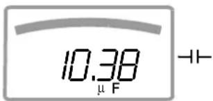
If the upper range limit of 12,000 digits is exceeded “DL” (overload) appears at the display.
Exceptions: "OL" appears as of 1200 digits for capacitance measurement, and as of 5100 digits for diode testing.
4.3.2 Analog Display
Measured Value, Polarity
The analog display demonstrates the dynamic performance of a moving-coil mechanism. This display is especially advantageous for observing measured value fluctuation, and for balancing procedures.
Two different display modes can be selected in the "SET" menu with the help of the "R.d SP" parameter (see chapter 6.4):
- Bar graph - Pointer: The current measured value is tracked in real-time.
The analog scale displays a negative range of 2 scale divisions for the measurement of zero-frequency quantities, allowing for precise observation of measured value fluctuation around zero. If the measured value exceeds the negative range of 2 scale divisions, polarity is reversed at the analog display.
Scaling of the analog scale is automatic. This is very helpful for manual measuring range selection.
Overranging
Overranging in the positive range is displayed by means of the right triangle symbol.
Refresh Rate
In the bar graph and pointer modes, the analog display is refreshed 40 times per second.
4.4 Measured Value Storage: DATA (auto-hold / compare)
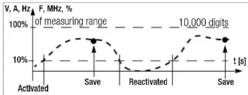
An individual measured value can be automatically “frozen” with the DATA function (auto-hold). This is useful, for example, when contacting the measuring points with the test probes requires your full attention. After the measuring signal has been applied and the measured value has settled in in accordance with the “condition” listed in the table below, the measured value is frozen at the digital display and an acoustic signal is generated. The test probes can now be removed from the measuring points, and the measured value can be read from the digital display. If the measuring signal falls below the value specified in the table, the function is reactivated for storage of the next value.
Measured Value Comparison (DATA Compare)
If the currently frozen value deviates from the first saved value by less than 100 digits, the acoustic signal is generated twice. If deviation is greater than 100 digits, only a brief acoustic signal is generated.

Note
The DATA function has no effect on the analog display, at which the current measured value continues to appear. However, when the digital display if “frozen”, the decimal point is fixed as well (fixed measuring range, symbol: MAN). The selected measuring range should not be manually changed as long as the DATA function is active.
The DATA function is deactivated by pressing and holding the DATA/MIN/MAX key (for approx. 1 second), when the measuring function is changed or when the instrument is switched off and back on again.
line
| t [s] | F, MHz, % | | ------------ | --------- | | Activated | 10% | | Save | 100% | | Reactivated | 10% | | Save | 100% || DATA Function | Press DATA / Min/Max | Condition Response from Instrument | ||||
| Measuring Function | Measuring Signal | Display | Acoustic | |||
| MV Digital | DATA | |||||
| Activate Brief blinks Once | ||||||
| Save (stabilized measured value) | V, A, F, Hz, MHz, % | >10% of R | Is dis-played | Static | Once Twice 2) | |
| Ω ➕ | ≠OL | |||||
| Reactivate 1) | V, A, F, Hz, MHz, % | <10% of R | Stored MV | Blinks | ||
| Ω ➕ | =OL | |||||
| Change to Min/Max | Brief See table in chapter 4.4.1 | |||||
| Exit Long | Is cleared | Is cleared | Twice | |||
1) Reactivation results from falling short of specified measured value limits.
^2) Two acoustic signals are generated the first time a measured value is saved as a reference value. For subsequent data hold, two acoustic signals are only generated if the currently frozen value deviates from the first saved value by less than 100 digits.
Key: MV = measured value, R = measuring range
Control Functions
Example
The voltage measuring range is set manually to 10 V.
The first measured value is 5 V, which is stored to memory because it is greater than 10% of the measuring range (= 1 V), and is thus reliably above the background noise level. As soon as the measured values drops to less than 10% of the measuring range, i.e. amounts to less than 1 V which corresponds to removal of the test probes from the measuring point, the instrument is ready to store a new value.
4.4.1 Saving Minimum and Maximum Values - MIN/MAX Function
Minimum and maximum measured values applied to the measuring instrument's input after the Min/Max function has been activated can be "frozen" at the display. The most important use of this function is the determination of minimum and maximum values during long-term measured value observation.
The Min/Max function can be activated in all measuring functions.
The Min/Max function has no effect on the analog display, at which the momentary measured value continues to appear.
Apply the measured quantity to the instrument and set the measuring range with the MAN / AUTO key before activating the Min/Max function.
The Min/Max function is deactivated by pressing and holding the DATA/MIN/MAX key (for approx. 1 second), when the measuring function is changed or when the instrument is switched off and back on again.

Note
As opposed to the DATA function, the Min/Max function can also be used for temperature measurement.
| Min/Max Function | Press DATA / Min/Max | Min. and Max. Measured Values | Response from Instrument | ||
| Display | Acoustic Signal | ||||
| Measured Value Digital | Max. Min. | ||||
| 1 Activate and save | 2 x brief are saved | Momentary measured value | Max and min. | 2 x | |
| 2 Save and display | Brief | Storage continues in background, new min. and max. values are displayed. | Saved min. value | Min. 1 | x |
| Brief | Saved max. value | Max. 1 | x | ||
| 3 Return to 1 | Brief | Same as 1, stored values are not deleted | Same as 1 | Same as 1 | 1 x |
| Stop Long Are deleted | Momentary measured value | Is deleted | 2 x | ||
4.5 Measurement Data Recording (METRAHIT X-TRA/OUTDOOR and SECULIFEHIT AM/MD only)
The METRAHIT X-TRA/OUTDOOR/SECULIFEHITAM/MD is capable of recording measurement data using an adjustable sampling rate for long periods of time in the form of measurement series. Data are stored to a battery backed memory module, and are retained even after the multimeter is switched off. The system acquires measured values relative to real-time.
Stored measured values can subsequently be read out with the help of METRAwin 10 software. The only prerequisite is a PC which is connected by means of an interface cable to the USB X-TRA bi-directional interface adapter, which is in turn plugged onto the METRAHIT X-TRA/OUTDOOR or SECULIFEHITAM/MD. See also chapter 7.
Memory Parameters Overview (METRAHIT X-TRA/OUTDOOR or SECULIFEHITAM/MD only)
| Parameter Page: header | |
| CLEAR | 24: Clear Memory |
| ENPTY | 24: Clear Memory – appears after CLEAR |
| OCCUP | 24: Querying Memory Occupancy |
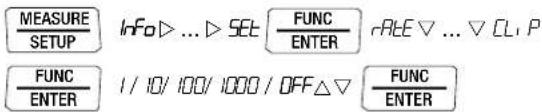
| rAtE | 48: rAtE – set the sampling rate (HIT X-TRA/OUTDOOR/HITAM/MD only) |
| StArt | 23: Starting Recording via Menu Functions |
| StoP | 24: Ending Recording |
The STORE Menu Function
First set the sampling rate for memory mode operation (see rALE parameter in chapter 6.4), and then start memory mode operation.
First select the desired measuring function and an appropriate measuring range.
Check the battery charge level before starting long-term measurement recordings (see chapter 6.3).
Connect the NA X-TRA power pack if required.
Starting Recording via Menu Functions
Switch to the "SET" mode by pressing MEASURE I SETUP and select the "StorE" menu.
$$ \boxed {\frac {\text { MEASURE }}{\text { SETUP }}} \quad \text { Info } > \dots > \text { StorE } \boxed {\frac {\text { FUNC }}{\text { ENTER }}} 0 0 0. 0 \% > \text { Start } \boxed {\frac {\text { FUNC }}{\text { ENTER }}} $$
Memory mode operation is started by pressing FUNC | ENTER. STORE appears underneath the analog display and indicates that memory mode operation has been activated. "StoP" appears at the digital display.
Press MEASURE | SETUP in order to return to the measuring function.
Control Functions
During Recording
STORE is displayed underneath the analog display during memory mode operation, and memory occupancy can be controlled:
$$ S t o P \triangleright 000.3\% $$
The following message appears as soon as memory is full: “00.0%”. In order to be able to observe measured values during recording, switch to the measuring function by pressing MEASURE | SETUP. The display is returned to the memory menu after once again pressing MEASURE | SETUP.
A new memory block is created when another measuring function is selected with the rotary switch or the FUNC I ENTER key. Data storage then continues automatically.
Ending Recording
“Sto” appears at the display after pressing MEASURE | SETUP.

569-7
Acknowledge the "ScoP" display by pressing FUNC | ENTER. STORE is cleared from the display, indicating that recording has been ended.
Press MEASURE I SETUP in order to return to the measuring function.
→Memory mode operation can also be exited by switching the multimeter off.
Querying Memory Occupancy
Memory occupancy can be queried during recording with the help of the “Info” menu (see also chapter 6.3).
Memory occupancy range: 000.1% to 099.9%.

Memory occupancy can be queried before recording is started via the "Store" menu.

Clear Memory
This function deletes all measured values from memory! This function cannot be executed during memory mode operation.


Control Functions
5 Measurements
5.1 Voltage Measurement
Notes Regarding Voltage Measurement
- The multimeter may only be operated with installed batteries or rechargeable batteries. Dangerous voltages are otherwise not indicated, and the instrument may be damaged.
- The multimeter may only be operated by persons who are capable of recognizing contact hazards and taking the appropriate safety precautions. Contact hazards exist anywhere, where voltages of greater than 33 V RMS may occur. The test probes may only be only gripped up to the finger guard. Do not touch the metallic test probes under any circumstances.
- Avoid working alone when taking measurements which involve contact hazards. Be certain that a second person is present.
- Maximum permissible voltage between the connector sockets, (9 and 10) and ground (8) is 1000 V for measuring category III, and 600 V for measuring category IV. Exception SECULIFE HITAM/HITMD: 600 V CAT III and 300 V CAT IV.
- Be prepared for the occurrence of unexpected voltages at devices under test (e.g. defective devices). For example, capacitors may be dangerously charged.
- No measurements may be made with this instrument in electrical circuits with corona discharge (high-voltage).
-
Special care is required when measurements are made in HF electrical circuits. Dangerous pulsating voltages may be present.
-
Be aware of the fact that dangerous voltage spikes are not displayed during measurement with the low-pass filter. We recommend measuring voltage without the low-pass filter first, in order to be able to detect any dangerous voltages.
- Be absolutely certain that the measuring ranges are not overloaded beyond their allowable capacities. Limit values are included in chapter 8, “Technical Data”, in the table entitled “Measuring Functions and Measuring Ranges” in the “Overload Capacity” column.
Scope of Functions, Voltage Measurement
| Function | METRAHIT X-TRA OUTDOOR/ SECULIFEHIT AM/MD | METRAHIT TECH | METRAHIT PRO | METRAHIT BASE |
| V AC / Hz TRMS (Ri ≥ 9 MΩ) | • | • | • | • |
| V AC / LP filter 1 kHz ^1) (Ri = 1 MΩ ^2) ) TRMS | • | • | • | — |
| V AC+DC TRMS (Ri ≥ 9 MΩ) | • | • | • | • |
| V DC (Ri ≥ 9 MΩ) | • | • | • | • |
| MHz at 5 V AC | • — | — | — | |
| Duty cycle as % | • — | — | — | |
| Freq. response, V AC | 20 kHz 10 kHz 10 kHz 1 kHz | |||
^1) A 1 kHz low-pass filter can be used in this case, in order to filter out high frequency pulses of greater than 1 kHz, for example when performing measurements at pulsed motor drives.
^2) Input resistance of approx. 1 MΩ. Erroneous displays resulting from capacitive coupling during voltage measurement in power supply systems are reduced to a minimum in this way.
5.1.1 Direct and Pulsating Voltage Measurement, V DC and V (DC+AC)

Note
Only to observe for METRAHIT TECH: Set the CL, P parameter to OFF in the current clip setup menu. Otherwise all measured values are displayed in amperes, and are corrected by the amount resulting from the selected transformation ratio for an interconnected clip-on current sensor.
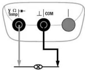
In accordance with the voltage to be measured, turn the rotary switch to V or V.
Connect the measurement cables as shown.
The “⊥” connector jack should be grounded.

Note
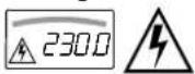
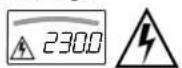
An intermittent acoustic signal warns the operator if the measured value exceeds the upper range limit in the 1000 V range.
Make sure that a current measuring range ("A") has not been activated when the multimeter is connected for voltage measurement! If the fuse's blowing limits are exceeded as a result of operator error, both the operator and the instrument are in danger! With the rotary switch in the V position, the multimeter is always set to the 1 V measuring range immediately after it is switched on. As soon a the MAN / AUTO key is pressed, and assuming the measured value is less than 90 mV, the multimeter is switched to the mV measuring range.
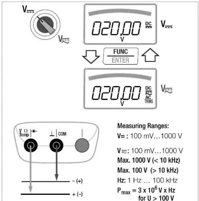
Measuring Ranges:
$$ \mathrm{V} =: 1 0 0 \mathrm{mV} \dots 1 0 0 0 \mathrm{V} $$
$$ V \approx : 1 0 0 \mathrm{mV} \dots 1 0 0 0 \mathrm{V} $$
$$ \text { Max. } 1 0 0 0 \mathrm{V} (< 1 0 \mathrm{kHz}) $$
$$ \text { Max. } 1 0 0 \mathrm{V} (> 1 0 \mathrm{kHz}) $$
$$ \mathrm{Hz}: 1 \mathrm{Hz} \dots 1 0 0 \mathrm{kHz} $$
$$ \begin{array}{c} P _ {\max} = 3 \times 1 0 ^ {6} \mathrm{V} \times \mathrm{Hz} \ \text { for U } > 1 0 0 \mathrm{V} \end{array} $$
Warnings regarding dangerous voltage:
$$
5 5 \mathrm{VAC} \text { or } > 7 0 \mathrm{VDC:} $$
$$
1 0 0 0 \mathrm{V}: \square) \text { - } \text { - } $$
V/Hz, Ω, Temperature, and A/Hz Measurements
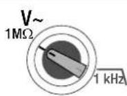
5.1.2 Alternating Voltage Measurement with 1 MΩ Load Resistance and Frequency Measurement with Selectable Low-Pass Filter (METRAHIT X-TRA/OUTDOOR/TECH/PRO/SECULIFEHITAM/MD only)
The measuring instrument includes a V_1M switch position for electricians with an input resistance of approximately 1 MΩ. Erroneous displays resulting from capacitive coupling during voltage measurement in power supply systems are reduced to a minimum in this way.

Note
METRAHIT TECH: see note in chapter 5.1.1.
In accordance with the voltage to be measured, turn the rotary switch to V_1M or 1 kHz
Connect the measurement cables as shown.
The “⊥” connector jack should be grounded.
Voltage Measurement

Note
An intermittent acoustic signal warns the operator if the measured value exceeds the upper range limit in the 1000 V range.
Make sure that a current measuring range ("A") has not been activated when the multimeter is connected for voltage measurement! If the fuse's blowing limits are exceeded as a result of operator error, both the operator and the instrument are in danger!
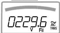
- You can switch back and forth between voltage measurement with and without low-pass filter.
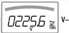
Press the FUNC I ENTER multifunction key repeatedly until unit of measure V or V/Fil appears at the display.
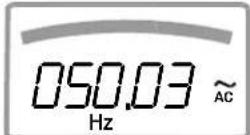
Frequency Measurement
- Apply the measured quantity is the same way as for voltage measurement.
→Manually select the measuring range for the voltage amplitude. When the instrument is switched to frequency measurement, the previously selected voltage measuring range remains active.
You can switch back and forth between frequency measurement with and without low-pass filter. Press the FUNC I ENTER multifunction key repeatedly until unit of measure Hz or Hz/Fil appears at the display. Lowest measurable frequencies and maximum allowable voltages are included in chapter 8, "Technical Data".
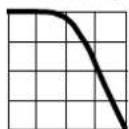
Measurement with Low-Pass Filter

Attention!
Be aware of the fact that dangerous voltage spikes are not displayed during this type of measurement (see also "Voltage Comparator". We recommend measuring voltage without the low-pass filter first, in order to be able to detect any dangerous voltages.
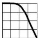
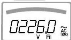
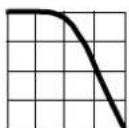
A 1 kHz low-pass filter can be activated if required, in order to filter out high frequency pulses of greater than 1 kHz, for example when performing measurements at pulsed motor drives, i.e. undesired voltages of greater than 1 kHz can be suppressed. The active low-pass filter is indicated by the Fil display. The multimeter is automatically switched to manual measuring range selection.
flowchart
graph TD
    A["Temp Sensor"] --> B["COM Gate"]
    B --> C["Output Signal"]
    D["Feedback Loop"] --> B
Measuring Ranges:
V\~: 100 mV...1000 V
Max. 1000 V (< 10 kHz)
Max. 100 V (> 10 kHz)
Hz: 1 Hz ... 100 kHz
P_max = 3 × 10^6 V x Hz for U > 100 V
Warnings regarding dangerous voltage:
55 V AC or > 70 V DC:
1000 V: □)
Voltage Comparator for Displaying Dangerous Voltage
The input signal or measuring signal is checked by a voltage comparator for dangerous spikes, because these do not appear at the display when the low-pass filter is used.
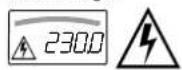
At voltages of greater than 55 V AC or 70 V DC, a danger symbol appears at the display:


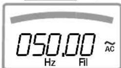
V\~ with Filter

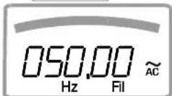
Hz with Filter


V/Hz, Ω, Temperature, - and A/Hz Measurements
5.1.3 Alternating Voltage and Frequency Measurement V AC and Hz with Selectable Low-Pass Filter (METRAHIT X-TRA/OUTDOOR/TECH/PRO/SECULIFEHITAM/MD only)

Note
METRAHIT TECH: see note in chapter 5.1.1.
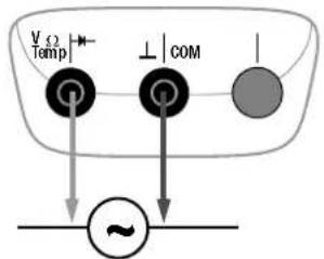
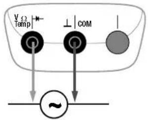
In accordance with the voltage or frequency to be measured, turn the rotary switch to V\~ or Hz.
Connect the measurement cables as shown.
The “⊥” connector jack should be grounded.
Voltage Measurement

Note
An intermittent acoustic signal warns the operator if the measured value exceeds the upper range limit in the 1000 V range.
Make sure that a current measuring range ("A") has not been activated when the multimeter is connected for voltage measurement! If the fuse's blowing limits are exceeded as a result of operator error, both the operator and the instrument are in danger!
- You can switch back and forth between voltage measurement with and without low-pass filter.
Press the FUNC | ENTER multifunction key repeatedly until unit of measure V or V/Fil appears at the display.
Frequency Measurement
Apply the measured quantity is the same way as for voltage measurement.
Manually select the measuring range for the voltage amplitude. When the instrument is switched to frequency measurement, the previously selected voltage measuring range remains active.
You can switch back and forth between frequency measurement with and without low-pass filter.
Press the FUNC I ENTER multifunction key repeatedly until unit of measure Hz or Hz/Fil appears at the display.
Lowest measurable frequencies and maximum allowable voltages are included in chapter 8, "Technical Data".
Measurement with Low-Pass Filter

Attention!
Be aware of the fact that dangerous voltage spikes are not displayed during this type of measurement (see also "Voltage Comparator". We recommend measuring voltage without the low-pass filter first, in order to be able to detect any dangerous voltages.
A 1 kHz low-pass filter can be activated if required, in order to filter out high frequency pulses of greater than 1 kHz, for example when performing measurements at pulsed motor drives, i.e. undesired voltages of greater than 1 kHz can be suppressed.
The active low-pass filter is indicated by the Fil display. The multimeter is automatically switched to manual measuring range selection.
The specified measuring accuracy is not achieved when the filter is activated and signals are greater than 100 Hz.
flowchart
graph TD
    A["Temp Sensor"] --> B["COM"]
    B --> C["Output Signal"]
    D["Feedback Loop"] --> B
Measuring Ranges:
V\~: 100 mV...1000 V
Max. 1000 V (< 10 kHz)
Max. 100 V (> 10 kHz)
Hz: 1 Hz ... 100 kHz
P_max = 3 × 10^6 V x Hz for U > 100 V
Warnings regarding dangerous voltage:
55 V AC or > 70 V DC:
1000 V: □)
Voltage Comparator for Displaying Dangerous Voltage
The input signal or measuring signal is checked by a voltage comparator for dangerous spikes, because these do not appear at the display when the low-pass filter is used.
At voltages of greater than 55 V AC or 70 V DC, a danger symbol appears at the display:


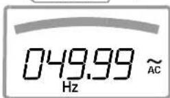
V\~
FUNC
ENTER


V\~ with Filter
Hz
FUNC
ENTER


Hz with Filter
V\~ 1 kHz
FUNC
ENTER

Hz 1 kHz
FUNC
ENTER

5.1.4 Frequency and Duty Cycle Measurements
(METRAHIT X-TRA/OUTDOOR/SECULIFEHITAM/MD only)
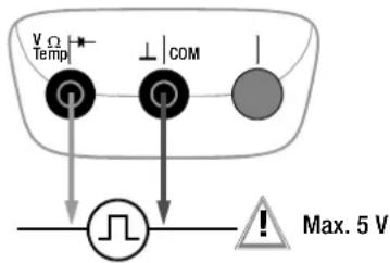
Set the rotary switch to MHz or %.
Connect the measurement cables as shown.
Make sure that a current measuring range ("A") has not been activated when the multimeter is connected for frequency or duty cycle measurement!

Attention!
The applied signal voltage may not exceed 5 V.
Frequency Measurement, MHz
A 5 V signal with a frequency of up to 1 MHz is measured and displayed using MHz as a unit of measure. Pulse frequency demonstrates the reciprocal value of pulse period.
Duty Cycle Measurement, t_E/t_P
The ratio of pulse duration to pulse period is measured with periodic square-wave signals and displayed as a percentage.
$$ \text { duty cycle } (\%) = \frac {\text { pulse duration } (t _ {E})}{\text { pulse period } (t _ {P})} \cdot 1 0 0 $$

Note
The applied frequency must remain constant during duty cycle measurement.
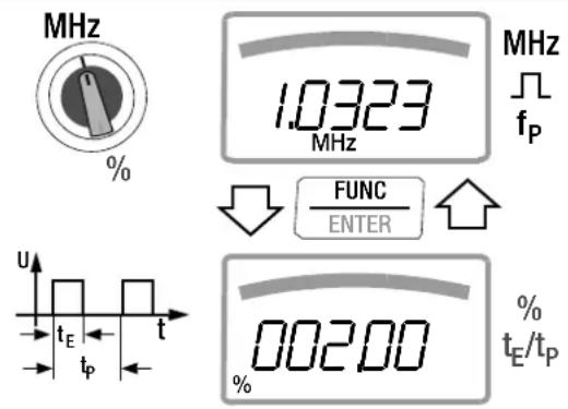
Pulse Time Quantities
f_p pulse frequency = 1/t_p
t_E pulse duration
t_p pulse period
t_P-t_E interpulse period
t_E/t_P pulse or duty cycle
Measuring Ranges:
| MHz t | E/t_P |
| 100 Hz ... 1 kHz | 2 ... 98% |
| ... 10 kHz | 5 ... 95% |
| ... 100 kHz | 10 ... 90% |
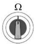
5.2 Resistance Measurement, Ω
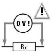
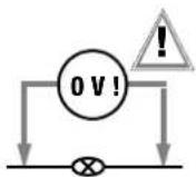
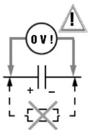
➢Disconnect supply power from the electrical circuit of the device to be measured, and discharge all high-voltage capacitors.
Make sure that the device under test is voltage-free.
Interference voltages distort measurement results!
Refer to chapter 5.1.1 regarding testing for the absence of voltage with the help of the direct voltage measurement.
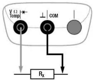
Set the rotary switch to "Ω".
Connect the device under test as shown.

Note
Use short or shielded measurement cables in the case of high-impedance resistance.
Improving Accuracy by means of Zero Balancing
Cable resistance and contact resistance can be eliminated in all measuring ranges by means of zero balancing (see chapter 4.2).
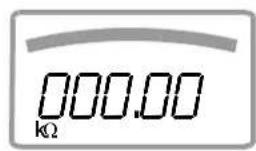
Ω
Measuring Ranges:
100 Ω ... 40 MΩ
flowchart
graph TD
    A["Temp V"] --> B["Gate"]
    C["COM ⊥"] --> D["Gate"]
    E["Rx"] --> F["Load"]
    G["V"] --> H["Power Supply"]
    I["Ω"] --> J["Power Supply"]
V/Hz, Ω, Temperature, - and A/Hz Measurements
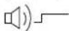
5.3 Continuity Test
→Disconnect supply power from the electrical circuit of the device to be measured, and discharge all high-voltage capacitors.
Make sure that the device under test is voltage-free. Interference voltages distort measurement results!
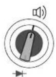
Set the rotary switch to .
Connect the conductor path under test as shown.
Depending upon the selected limit value, the multimeter generates a continuous acoustic signal in the case of continuity or short-circuit, i.e. at a value of less than the selected limit value.
“DL” appears at the display in the case of an open connection.
The limit value can be adjusted in the "SEbP" menu (see also chapter 6.4):
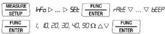
(10 = default setting)
R < 1, 10, 20, 30, 40, 90 Ω
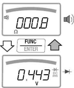
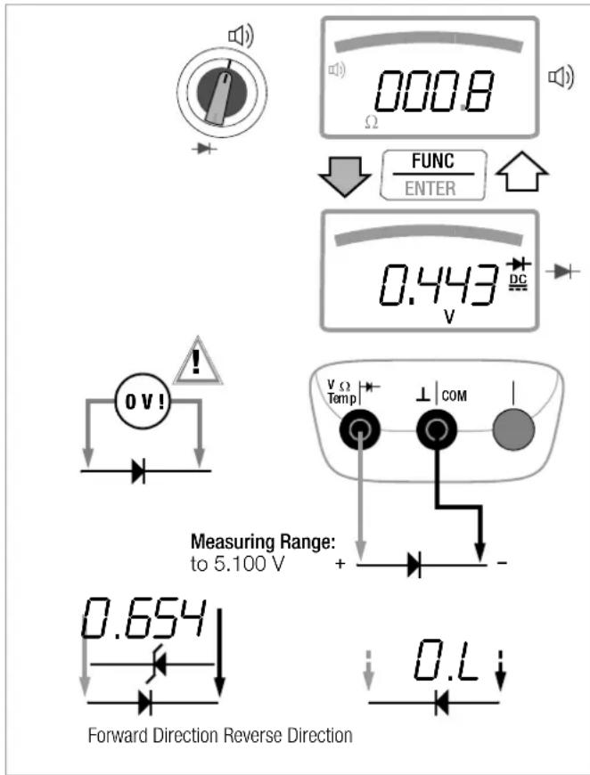
5.4 Diode Testing with a Constant Current of 1 mA
→Disconnect supply power from the electrical circuit of the device to be measured, and discharge all high-voltage capacitors.
Make sure that the device under test is voltage-free.
Interference voltages distort measurement results!
Refer to chapter 5.1.1 regarding testing for the absence of voltage with the help of the direct voltage measurement.
Set the rotary switch to .
→Press the FUNC | ENTER key.
Connect the device under test as shown.
Conducting Direction and Short-Circuit
The instrument displays forward voltage in volts (display: 4 places). As long as voltage drop does not exceed the maximum display value of 5.1 V, several series connected components or reference diodes can be tested with a small reference voltage and reference diodes.
Reverse Direction and Interruption
The measuring instrument indicates overload 0L

Note
Resistors and semiconductor paths connected in parallel to the diode distort measurement results!
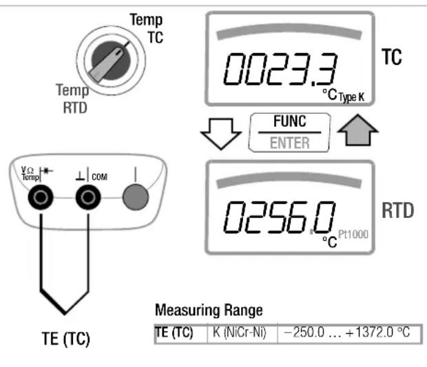
5.5 Temperature Measurement
Temperature measurement is performed with a type K thermocouple (accessory, not included), which is connected to the voltage input. Alternatively, a Pt100 or Pt1000 resistance thermometer can be used with the METRAHIT X-TRA/OUTDOOR/SECULIFEHITAM/MD.
Selecting the Unit of Measure for Temperature

(°C = default setting)
5.5.1 Measurement with Thermocouples, Temp TC
Set the rotary switch to "Temp TC".

Note
METRAHIT X-TRA/OUTDOOR/SECULIFEHITAM/MD only:
The last selected temperature measurement or the last selected temperature sensor, i.e. type K or Pt100/Pt1000, remains in memory and is accordingly displayed. Press the FUNC I ENTER key in order to change to the other measuring function if required.
The reference temperature is measured at the internal reference junction (see parameter “ tLEnP ” in chapter 6.3 regarding querying).

Note
The internal reference temperature (temperature of the internal reference junction) is measured by a temperature sensor inside of the instrument. This may be somewhat above room temperature as a result of internal heat-up, or moving from warmer to colder surroundings or vice versa.
Connect the sensor to the two accessible jacks. The instrument displays the measured temperature using the selected unit of measure.
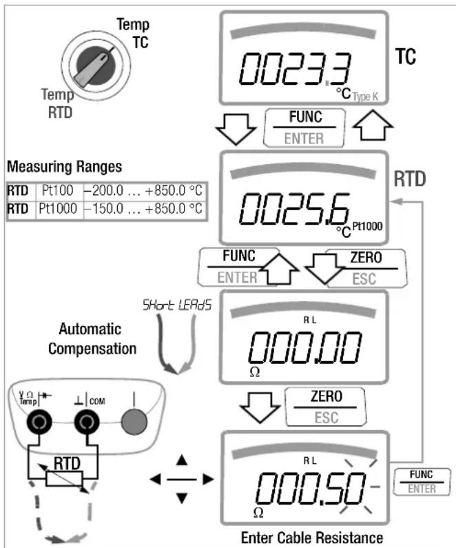
5.5.2 Measurement with Resistance Thermometers (METRAHIT X-TRA/OUTDOOR/SECULIFEHITAM/MD only)
Set the rotary switch to "Temp TC" or "TempRTD".
The last selected temperature measurement or sensor, i.e. type K or Pt100/Pt1000, remains in memory and is accordingly displayed. Press the FUNC I ENTER key in order to change to the other measuring function if required. The sensor type, i.e. Pt100 or Pt1000, is detected automatically and displayed.
There are two different ways to compensate for cable resistance:
Automatic Compensation
Press the ZERO | ESC key.
"Short leads" appears at the display.
If you prefer to enter cable resistance directly, you can skip the following entry prompt.
Short circuit the measuring instrument's connector cables.
"000.00" appears at the display. After pressing the FUNC I
ENTER key, automatic compensation of cable resistance is activated for all subsequent measurements. The short-circuit can now be eliminated, and the device is ready for use.
Entering Cable Resistance
Press the ZERO | ESC key once again in the automatic compensation menu.
→Enter the known resistance of the connector cables with the scroll keys: Select the digit to be changes with the ◀▷ keys, and change the respectively selected digit with the ▽△ keys. The default value is 0.43 Ω. Values can be selected within a range of 0 to 50 Ω.
Upon pressing the FUNC I ENTER key, the selected value is activated and the display is returned to the measuring function. Cable resistance remains in memory even after the instrument has been switched off.
flowchart
graph TD
    A["Temp TC"] --> B["0023.3 °C Type K"]
    B --> C["FUNC ENTER"]
    C --> D["Measuring Ranges"]
    D --> E["RTD Pt100 -200.0 ... +850.0 °C"]
    D --> F["RTD Pt1000 -150.0 ... +850.0 °C"]
    G["Automatic Compensation"] --> H["Short LERdS"]
    H --> I["RTD"]
    I --> J["COM"]
    J --> K["Enter Cable Resistance"]
    K --> L["FUNC ENTER"]
    L --> M["ZERO ESC"]
    M --> N["RL Ω"]
    N --> O["ZERO ESC"]
    O --> P["RL Ω"]
V/Hz, Ω, Temperature, - and A/Hz Measurements
5.6 Capacitance Measurement (METRAHIT X-TRA/OUTDOOR/SECULIFEHITAM/MD and METRAHIT TECH only)
→Disconnect supply power from the electrical circuit of the device to be measured, and discharge all high-voltage capacitors.
Make sure that the device under test is voltage-free.
Capacitors must always be discharged before measurement is performed.
Interference voltages distort measurement results! Refer to chapter 5.1.1 regarding testing for the absence of voltage with the help of the direct voltage measurement.
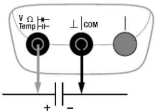
Set the rotary switch to " "
Connect the (discharged!) device under test to the sockets with the measurement cables as shown.

Note
The “−” pole of polarized capacitors must be connected to the “⊥” jack.
Resistors and semiconductor paths connected in parallel to the capacitor distort measurement results!
Measuring Ranges:
10 nF ... 1000 μF
5.7 Current Measurement
Notes Regarding Current Measurement
- The multimeter may only be operated with installed batteries or rechargeable batteries. Dangerous currents are otherwise not indicated, and the instrument may be damaged.
- Set up the measuring circuit in a mechanically secure fashion, and secure it against inadvertent breaks. Select conductor cross-sections and lay out connections such that they do not overheat.
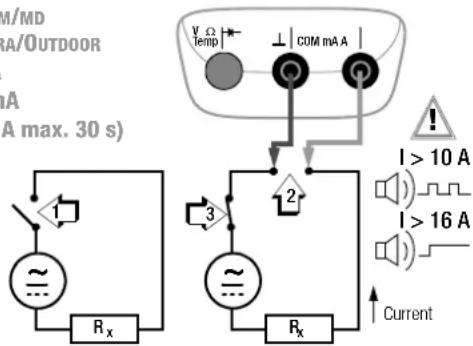
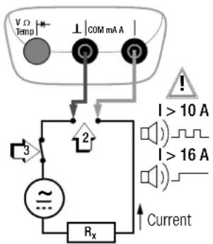
- An intermittent acoustic signal warns of current greater than 10 A. An continuous acoustic signal warns of current greater than 16 A.
- The input for the current measuring range is equipped with a fuse link. Maximum permissible voltage for the measuring circuit (= rated voltage of the fuse) is 1000 V AC/DC. Use specified fuses only! The fuse must have a breaking capacity of at least 30 kA.
- If the fuse for the active current measuring range blows, "FUSE" appears at the digital display, and an acoustic signal is generated at the same time.
- If a fuse should blow, eliminate the cause of overload before placing the instrument back into service!
- Fuse replacement is described in chapter 9.3.
- Be absolutely certain that the measuring ranges are not overloaded beyond their allowable capacities. Limit values are included in chapter 8, “Technical Data”, in the table entitled “Measuring Functions and Measuring Ranges” in the “Overload Capacity” column.
Scope of Functions, Current Measurement, Direct Connection
| Function | METRAHIT X-TRA OUTDOOR SECULIFEHIT AM/MD | METRAHIT TECH | METRAHIT PRO | METRAHIT BASE |
| A AC / Hz ~ 100 μA | 1/10/100 mA1 A / 10 (16) A | 10/100 mA1 A / 10 (16) A | 1 A / 10 (16) A | — |
| A AC+DC TRMS ≈ | 100 μA1/10/100 mA1A / 10 (16) A | 10/100 mA1A / 10 (16) A | 1 A / 10 (16) A | — |
| A DC 100 μA = | 1/10/100 mA1A / 10 (16) A | 10/100 mA1A / 10 (16) A | 1 A / 10 (16) A | — |
| 1000 V fuse | • | • | • | — |
Scope of Functions, Current Measurement via Clip-On Current Sensor
| Function | METRAHIT X-TRA OUTDOOR SECULIFEHIT AM/MD | METRAHIT TECH | METRAHIT PRO | METRAHIT BASE |
| Transformation Factor ≥slant C | — • — • | |||
| A AC ≥slant Hz | — • — • | |||
| A AC+DC ≥slant C | — • — • | |||
| A DC ≥slant C | — • — • | |||
| Hz (A AC) | ... 30 kHz ... 30 kHz ... 30 kHz ... 30 kHz | |||
5.7.1 Direct and Pulsating Current Measurement, Direct Connection, A DC and A (DC+AC) (METRAHIT X-TRA/OUTDOOR/TECH/PRO only)
- First disconnect supply power from the measuring circuit or the power consumer (1), and discharge any capacitors.
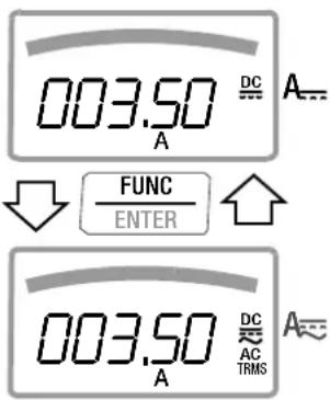
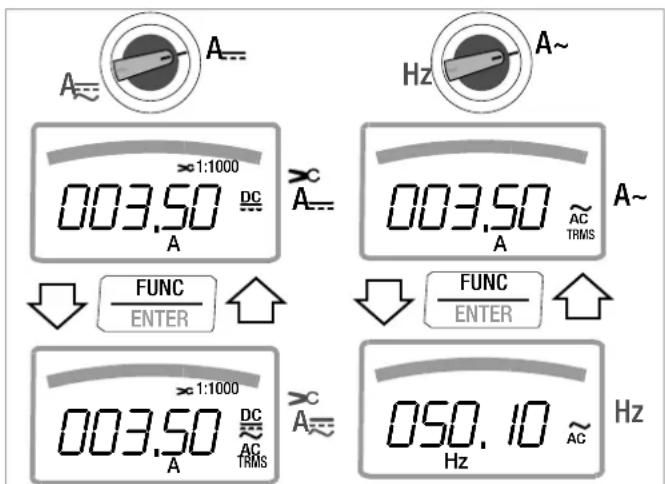
In accordance with the current to be measured, turn the rotary switch to A or A
Select the current type appropriate for the measured quantity by briefly pressing the FUNC I ENTER multifunction key. Each time the key is pressed, the instrument is switched back and forth between A DC and A (DC + AC) TRMS , which is indicated by means of an acoustic signal. The current type is indicated at the LCD by means of the DC or the (DC+AC) TRMS symbol.
Safely connect the measuring instrument (without contact resistance) in series to the power consumer (2) as shown.
→Switch supply power to the measuring circuit back on (3).
Read the display. Make a note of the measured value if the instrument is not being operated in the memory mode or the transmission mode.
→Disconnect supply power from the measuring circuit or the power consumer (1) once again, and discharge any capacitors.
Remove the test probes from the measuring point and return the measuring circuit to its normal condition.
Measuring Ranges:
METRAHIT PRO
1 A / 10 A (16 A max. 30 s)
METRAHIT TECH
10 mA / 100 mA
1 A / 10 A (16 A max. 30 s)
SECULIFE HIT AM/MD
METRAHIT X-TRA/OUTDOOR
100 μA / 1 mA
10 mA / 100 mA
1 A / 10 A (16 A max. 30 s)
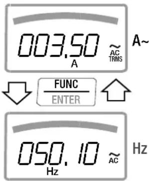
5.7.2 Alternating Current and Frequency Measurement, Direct Connection, A AC and Hz (METRAHIT X-TRA/OUTDOOR/TECH/PRO/SECULIFEHIT
→First disconnect supply power from the measuring circuit or the power consumer (1), and discharge any capacitors.
In accordance with the current or frequency to be measured, turn the rotary switch to A\~ or Hz.
Select the desired measured quantity by briefly pressing the FUNC I ENTER multifunction key. Each time the key is pressed, AC _TRMS and Hz are alternately selected, and switching is acknowledged with an acoustic signal.
Safely connect the measuring instrument (without contact resistance) in series to the power consumer as shown.
Switch supply power to the measuring circuit back on (3).
Read the display. Make a note of the measured value if the instrument is not being operated in the memory mode or the transmission mode.
Disconnect supply power from the measuring circuit or the power consumer (1) once again, and discharge any capacitors.
Remove the test probes from the measuring point and return the measuring circuit to its normal condition.


Current measurement may only be performed with installed batteries!
Measuring Ranges:
METRAHIT PRO
1 A / 10 A (16 A max. 30 s)
METRAHIT T ECH
10 mA / 100 mA
1 A / 10 A (16 A max. 30 s)
SECULIFEHIT AM/MD
METRAHIT X-TRA/OUTDOOR
100 μA / 1 mA
10 mA / 100 mA
1 A / 10 A (16 A max. 30 s)
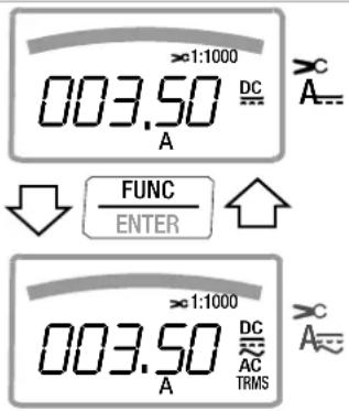
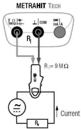
5.7.3 Direct and Pulsating Current Measurement with Clip-On Current Sensor, A DC and A (DC+AC) (METRAHIT T_ECH and METRAHIT B_ASE only)
Transformer Output, Voltage/Current
When a clip-on current sensor is connected to the multimeter (METRAHIT TECH: V input, METRAHIT BASE: V input), all current displays appear with the correct value in accordance with the selected transformation factor. The only prerequisite is that the current sensor is equipped with at least one of the below listed transformation factors, and that the factor has been previously selected in the following menu (CL, P ≠ OFF), see also chapter 6.4.
Current Clip Setup Menu
| MEASURESETUP | INF0▷...▷SET | FUNCENTER | RATE▽...▽CU P |
| FUNCENTER | I/10/100/1000/0FF△▽ | FUNCENTER |
| Trans. Factors CL , P | Measuring Ranges DMM Clip Types | |||
| 100 mV 1 V | 10 V | |||
| 1:11 mV / 1 mA | 100.00 mA | 1.0000 A | 10.000 A WZ12C | |
| 1:101m V / 10 mA | 1.0000 A | 10.000 A | 100.00 A | WZ12B, Z201A/B,METRAFLEX |
| 1:1001m V / 100 mA | 10.000 A | 100.00 A | 1000.0 A | Z202A/B,METRAFLEX |
| 1:10001 mV / 1 A | 100.00 A | 1000.0 A | (10000.0 A) | Z202A/B, Z203A/B,WZ12C,METRAFLEX |
Maximum allowable operating voltage is equal to the current transformer's nominal voltage. When reading the measured value, additional error resulting from the clip-on current sensor must also be taken into consideration.
(default setting: METRAHIT TECH: OFF, METRAHIT BASE: 1:1000)


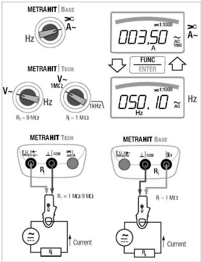
5.7.4 Alternating Current Measurement with Clip-On Current Sensor, A AC and Hz (METRAHIT TECH and METRAHIT BASE only)
Transformer Output, Voltage/Current
When a clip-on current sensor is connected to the multimeter (METRAHIT TECH: V input, METRAHIT BASE: V input), all current displays appear with the correct value in accordance with the selected transformation factor. The only prerequisite is that the current sensor is equipped with at least one of the below listed transformation factors, and that the factor has been previously selected in the following menu (CL, P ≠ OFF), see also chapter 6.4.
Current Clip Setup Menu
| MEASURESETUP | INF0▷...▷SET | FUNCENTER | RACE▽...▽CU P |
| FUNCENTER | I/10/100/1000/OFF△▽ | FUNCENTER |
| Trans. Factors CL , P | Measuring Ranges DMM Clip Types | |||
| 100 mV 1 V | 10 V | |||
| 1:11 mV / 1 mA | 100.00 mA | 1.0000 A | 10.000 A WZ12C | |
| 1:101m V / 10 mA | 1.0000 A | 10.000 A | 100.00 A | WZ12B, Z201A/B,METRAFLEX |
| 1:1001m V / 100 mA | 10.000 A | 100.00 A | 1000.0 A | Z202A/B,METRAFLEX |
| 1:10001 mV / 1 A | 100.00 A | 1000.0 A | (10000.0 A) | Z202A/B, Z203A/B,WZ12C,METRAFLEX |
Maximum allowable operating voltage is equal to the current transformer's nominal voltage. When reading the measured value, additional error resulting from the clip-on current sensor must also be taken into consideration.
(default setting: METRAHIT TECH: OFF, METRAHIT BASE: 1:1000)
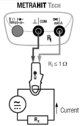
5.7.5 Direct, Pulsating and Current Measurement with Clip-On Current Transformer A DC, A (DC+AC), A AC and Hz (METRAHIT TECH only)
Transformer Output, Current/Current
When a clip-on current transformer is connected to the multimeter (METRAHIT TECH: mA/A input), all current displays appear with the correct value in accordance with the selected transformation factor. The only prerequisite is that the current transformer is equipped with at least one of the below listed transformation factors, and that the factor has been previously selected in the following menu ( _L, P _FF ), see also chapter 6.4.
Current Clip Setup Menu
| MEASURESETUP | Info ▷ ... ▷ SET | FUNCENTER | rAeE ▽ ... ▽ Cu P |
| FUNCENTER | I / IO/ 100/ 1000 / OFF △ ▽ | FUNCENTER |
| Trans. Factors CL , P | Measuring Ranges DMM Clip Types | |||
| 100 mA 1 A | 10 A | |||
| 1:11mA/1mA | 100,00 mA | 1,0000 A | 10,000 A | |
| 1:101mA/10mA | 1,0000 A | 10,000 A | 100,00 A | |
| 1:1001mA/100mA | 10,000 A | 100,00 A | 1000,0 A | |
| 1:10001 mA/1 A | 100,00 A | 1000,0 A | (10000,0 A) | WZ12A, WZ12D,WZ11A, Z3511,Z3512, Z3514 |
(default setting: METRAHIT TECH: OFF)
V/Hz, Ω, Temperature, and A/Hz Measurements
6 Device and Measuring Parameters
The instrument's "SET" mode (menu mode) makes it possible to set operating and measuring parameters, query information and activate the interface.
The menu mode is accessed by pressing the MEASURE I SETUP key, assuming that the instrument is switched on and set to "Measure" (measuring mode operation). "Info" appears at the display.
The main menus, i.e. the "SEt" and "tENP" menus, as well as the "SEnd" and "StorE" menus included with the METRAHIT X-TRA/OUTDOOR/SECULIFEHITAM/MD, are accessed, and the display is returned to "Info" by activating the ◀ ▷ △ ▽ keys (in any direction).
After selecting the desired main menu, sub-menus are accessed by pressing the FUNC I ENTER key.
The desired parameter is selected by repeatedly pressing the or key.
In order to check or change a parameter, acknowledge it with the FUNC I ENTER key.
The ◀▷ keys can be used to position the cursor at the entry position. The desired value is selected with the help of the △▽ keys.
Changes can only be accepted with the FUNC I ENTER key.
You can return to the sub-menu without making any changes by pushing the ZERO | ESC key, and to the main menu by pressing the same key once again etc.
→You can switch to the measuring mode from any menu level by pressing the FUNC I ENTER key.
After repeatedly pressing the MEASURE I SETUP key (without first turning the multimeter off), you can return to the last selected menu or parameter from the measuring mode.
Example: Setting Time
$$ \boxed {\frac {\text { MEASURE }}{\text { SETUP }}} \quad \text { Info } \triangleright \dots \triangleright \text { SET } \boxed {\frac {\text { FUNC }}{\text { ENTER }}} \quad \text { rAE } \triangledown \dots \triangledown t, \text { NE } $$
$$ \boxed {\frac {\text { FUNC }}{\text { ENTER }}} \quad 1 0: 2 4 (\mathrm{hh:mm}) \triangleleft \triangleright \triangle \triangledown \boxed {\frac {\text { FUNC }}{\text { ENTER }}} $$
Setting hours and minutes:
◀ ▷ Advance to desired entry position.
△▽ Change the setting, the entry position blinks. Press and hold the key to change the setting rapidly.
FUNC ENTER The new time setting is activated after acknowledgement.
6.1 Paths to the Various Parameters 6.2 List of All Parameters
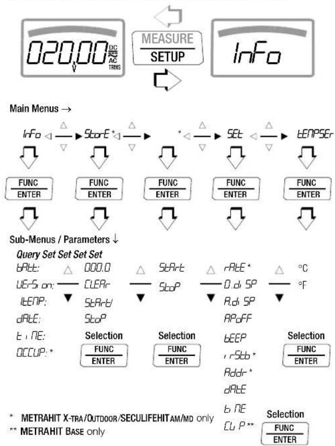
flowchart
graph TD
    A["020.00 DC/AC TRMS"] --> B["MEASURE/SETUP"]
    B --> C["Info"]
    D["Sub-Menus / Parameters"] --> E["Query Set Set Set"]
    E --> F["Selection"]
    F --> G["Selection"]
    G --> H["Selection"]
    H --> I["Selection"]
    style A fill:#f9f,stroke:#333
    style B fill:#ccf,stroke:#333
    style C fill:#cfc,stroke:#333
    style D fill:#fcc,stroke:#333
    style E fill:#ffc,stroke:#333
    style F fill:#cff,stroke:#333
    style G fill:#ffc,stroke:#333
    style H fill:#ffc,stroke:#333
    style I fill:#ffc,stroke:#333
| Parameter X | TRA | TECH | PRO | BASE | Page: Header |
| D.d SP | ● | ● | ● | ● | 48: 0.diSP – show/hide leading zeros |
| Addr | ● | — | — | — | 53: Configuring Interface Parameters |
| A.d SP | ● | ● | ● | ● | 49: A.diSP – analog display: select display mode |
| APoFF | ● | ● | ● | ● | 49: APoFF – specified time for automatic shutdown and continuous ON |
| bAtt | ● | ● | ● | ● | 48: bAtt – query battery voltage |
| bEEP | ● | ● | ● | ● | 49: bEEP – set the limit value for continuity testing |
| CLEAR | ● | — | — | — | 23: Measurement Data Recording (METRAHIT X-TRA/OUTDOOR and SECULIFEHITAM/MD only) |
| CU P | — | ● | — | ● | 42: Direct and Pulsating Current Measurement with Clip-On Current Sensor, A DC and A (DC+AC) (METRAHIT TECH AND METRAHIT BASE ONLY) |
| dATE | ● | ● | ● | ● | 48: dATE – query date, 50: dATE – enter date |
| EMPTY | ● | — | — | — | 23: Measurement Data Recording (METRAHIT X-TRA/OUTDOOR and SECULIFEHITAM/MD only) |
| Info | ● | ● | ● | ● | 48: Querying Parameters – Info Menu (as moving letters) |
| rStb | ● | — | — | — | 53: Configuring Interface Parameters |
| tCENP | ● | ● | ● | ● | 48: ItEMP – query reference temperature |
| OCCUP | ● | — | — | — | 23: Measurement Data Recording (METRAHIT X-TRA/OUTDOOR and SECULIFEHITAM/MD only) |
| RATE | ● | — | — | — | 48: rATE – set the sampling rate (HIT X-TRA/OUTDOOR/HITAM/MD only) |
| SEnd | ● | — | — | — | 52: Activating the Interface |
| SET | ● | ● | ● | ● | 48: Entering Parameters – SETUP Menu |
| SARt | ● | — | — | — | 23: Measurement Data Recording (METRAHIT X-TRA/OUTDOOR and SECULIFEHITAM/MD only) |
| StoP | ● | — | — | — | |
| Stort | ● | — | — | — | |
| tENP | ● | ● | ● | ● | 36: Temperature Measurement |
| t , NE | ● | ● | ● | ● | 48: tiME – query time, 50: tiME – set time |
| UErS on | ● | ● | ● | ● | 48: vErSion – query firmware version |
Device and Measuring Parameters
6.3 Querying Parameters – InFo Menu (as moving letters)
bAtt - query battery voltage
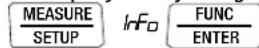
:2.756866
vErSion – query firmware version
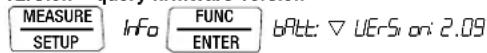
ItEMP – query reference temperature
The temperature of the internal reference junction is measured with a temperature sensor in close proximity to the input sockets.

dAtE - query date
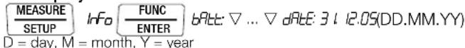
Date and time must be reentered after replacing the batteries.
tiME - query time

(hh:mm:ss)
h = hours, m = minutes, s = seconds
Date and time must be reentered after replacing the batteries.
OCCUP – query memory occupancy (METRAHIT X-TRA/OUTDOOR/HITAM/MD only)

6.4 Entering Parameters - SETUP Menu
rAtE - set the sampling rate (HIT X-TRA/OUTDOOR/HITAM/MD only)
The sampling rate specifies the time interval after which the respective measured value is transmitted to the interface, or to measured value memory.
Any one of the following sampling rates can be selected:
00:00.1, 00:00.2, 00:00.5, 00:01.0, 00:02.0, 00:05.0
[h:mm:ss.t] (h = hours, m = minutes, s = sec., t = tenths of a sec.)
0:00:10, 0:00:20, 0:00:30, 0:00:40, 0:00:50, 0:01:00, 0:02:00,
0:05:00, 0:10:00, 0:20:00, 0:30:00, 0:40:00, 0:50:00, 1:00:00,
2:00:00, 3:00:00, 4:00:00, 5:00:00, 6:00:00, 7:00:00, 8:00:00, 9:00:00
Setting the Sampling Rate
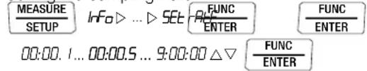
(00:00.5 = 0.5 seconds = default value)
0.diSP – show/hide leading zeros
This parameter determines whether or not leading zeros will appear in the measured value display.

0000.0 : with leading zeros (default setting)
0.0 : leading zeros suppressed

A.diSP – analog display: select display mode
One of two different display modes can be selected for the analog display:
- bR-C: bar graph
- Point: pointer
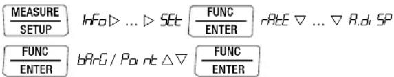
(bRrG = default value)
APoFF – specified time for automatic shutdown and continuous ON
The instrument is switched off automatically if the measured value remains unchanged for a long period of time, and if none of the keys or the rotary switch have been activated before the specified time "RPFF" (entered in minutes) has elapsed.
If the on setting is selected, the multimeter is set to continuous operation and on appears in the display to the right of the battery symbol. In this case, the multimeter can only be switched off manually. The "on" setting can only be cancelled by changing the respective parameter, and not by switching the instrument off.
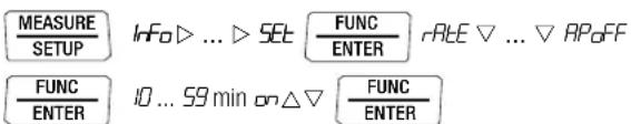
(10 minutes = default setting)
bEEP – set the limit value for continuity testing
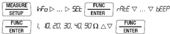
(10 Ω = default setting)
irStb – status of the infrared receiver in the stand-by mode (METRAHIT X-TRA/OUTDOOR/SECULIFEHITAM/MD only)
See chapter 7.2 on page 53 regarding settings.
Addr – select device address (METRAHIT X-TRA/OUTDOOR/SECULIFEHITAM/MD only
See chapter 7.2 on page 53.
dAtE - enter date
Entering the current date makes it possible to acquire measured values in real-time.
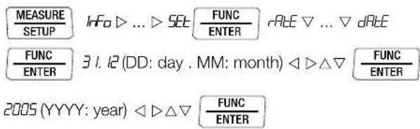
Date and time must be reentered after replacing the batteries.
tiME – set time
Entering the correct time makes it possible to acquire measured values in real-time.
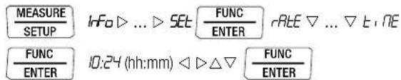
Date and time must be reentered after replacing the batteries.
CLIP - set transformation factor (METRAHIT BASE only)
See chapter 5.7.3 ff.
6.5 Default Settings
Previously entered changes can be undone, and the default settings can be reactivated. This may be advisable under the following circumstances:
• After the occurrence of software or hardware errors
- If you are under the impression that the multimeter does not work correctly
→Disconnect the device from the measuring circuit.
→Remove the batteries temporarily (see also chapter 9.2).
Simultaneously press and hold

and reinsert the batteries at the same time.
Device and Measuring Parameters
7 Interface Operation (METRAHIT X-TRA/OUTDOOR/SECULIFEHIT AM/MD only)
The METRAHIT X-TRA/OUTDOOR is equipped with an infrared interface for the transmission of measurement data to a PC. Measured data are optically transferred through the instrument housing by means of infrared light to an interface adapter (accessory), which is attached to the multimeter. The adapter's USB interface allows for the establishment of a connection to the PC via an interface cable. Beyond this, commands and parameters can be transmitted from the PC to the multimeter as well. The following functions can be executed:
- Configuration and read-out of measuring parameters
- Measuring function and measuring range selection
- Start measurements
- Read out stored measured values
7.1 Activating the Interface
The interface is automatically activated for receiving operation (multimeter receives data from the PC) as soon as the interface is addressed by the PC, assuming that the “,56b” parameter has been set to “,ron” (see chapter 7.2), or the instrument is already switched on (the first command wakes up the multimeter, but does not yet execute any further commands).
The “continuous transmission” operating mode is selected manually as described below. In this operating mode, the instrument continuously transmits measurement data to the PC via the interface adapter, which can then be displayed with the help of a terminal program.
Starting Continuous Transmission Operation with Menu Functions

The ↓ symbol blinks at the display in order to indicate interface operation.
Stopping Continuous Transmission Operation with Menu Functions
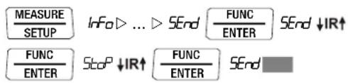
The ↓ symbol is cleared from the display.
Automatic Activation and Deactivation of Transmission Mode Operation
If the sampling rate is 10 seconds or longer, the display is switched off automatically between samples in order to prolong battery service life. The only exception is when the multimeter is set to continuous operation.
As soon as an event occurs, the display is automatically switched back on.
7.2 Configuring Interface Parameters
r56b - status of the infrared receiver in the stand-by mode
There are two possible switching statuses for the infrared interface when the multimeter is switched off:
, non: IR appears at the display and the infrared interface is active, i.e. signals such as making commands can be received, and power is consumed even though the multimeter is switched off.
, roFF: IR does not appear at the display and the infrared interface is switched off, signals cannot be received.
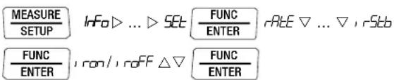
(1, rStb = 1, roFF = default setting)
Addr - Address
If several multimeters are connected to the PC via an interface adapter, a separate address can be assigned to each instrument. Address number 1 should be selected for the first instrument, 2 should be assigned to the second and so forth.
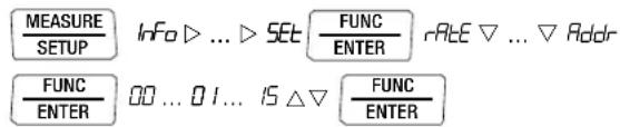
(15 = default setting)
Technical Data
8 Technical Data
| Meas. Function | Measuring Range | Resolution at Upper Range Limit11,999 1199 | Input Impedance | Intrinsic Errorunder Reference Conditions±(... % rdg. + ... d) | ±(... % rdg. + ... d) | ±(... % rdg. + ... d) | Overload Capacity2)Value Time | ||||
| = | ~ / ≈ | = | ~4) | ≈4) | |||||||
| V | 100 mV | 10 μV | ≥9 MΩ | ≥9 MΩ // < 50 pF | 0.09 + 5 with ZERO | 1 + 30 (>300 d)1) | 1 + 30 (>300 d)1) | 1000 VDCACRMSSine | continuous | ||
| 1 V | 100 μV | ≥9 MΩ | ≥9 MΩ // < 50 pF | 0.05 + 3 | 0.5 + 9 (>200 d) | 1 + 30 (>300 d) | |||||
| 10 V | 1 mV | ≥9 MΩ | ≥9 MΩ // < 50 pF | 0.05 + 3 | 0.5 + 9 (>200 d) | 1 + 30 (>300 d) | |||||
| 100 V | 10 mV | ≥9 MΩ | ≥9 MΩ // < 50 pF | 0.05 + 3 | 0.5 + 9 (>200 d) | 1 + 30 (>300 d) | |||||
| 1000 V | 100 mV | ≥9 MΩ | ≥9 MΩ // < 50 pF | 0.09 + 3 | 0.5 + 9 (>200 d) | 1 + 30 (>300 d) | |||||
| Voltage drop, approx. at upper range limit | = | ~4) | ≈4) | ||||||||
| AX-TRAOUTDOORPRO | X-TRA/OUTDOOR | 100 μA | 10 nA | 12 mV | 12 mV | 0.5 + 5 | 1.5 + 10 (>200 d) | 1.5 + 30 (>200 d) | 0.2 A | continuous | |
| 1 mA | 100 nA | 120 mV | 120 mV | 0.5 + 3 | 1.5 + 10 (>200 d) | 1.5 + 30 (>200 d) | |||||
| 10 mA | 1 μA | 16 mV | 16 mV | 0.5 + 3 | 1.5 + 10 (>200 d) | 1.5 + 30 (>200 d) | |||||
| 100 mA | 10 μA | 160 mV | 160 mV | 0.5 + 3 | 1.5 + 10 (>200 d) | 1.5 + 30 (>200 d) | |||||
| 1 A | 100 μA | 40 mV | 40 mV | 0.9 + 10 | 1.5 + 10 (>200 d) | 1.5 + 30 (>200 d) | 10 A: ≤ 5 min5)16 A: ≤ 30 s5) | ||||
| TECH | 10 mA | 1 μA | 600 mV | 600 mV | 0.9 + 10 | 1.5 + 10 (>200 d) | 1.5 + 30 (>200 d) | ||||
| 10 mA | 10 μA | 16 mV | 16 mV | 0.1 + 5 | 1 + 10 (>200 d) | 1.5 + 30 (>200 d) | 0.2 A | continuous | |||
| 1 A | 100 μA | 160 mV | 160 mV | 0.1 + 5 | 1 + 10 (>200 d) | 1.5 + 30 (>200 d) | |||||
| 10 A | 1 mA | 40 mV | 40 mV | 0.9 + 10 | 1 + 10 (>200 d) | 1.5 + 30 (>200 d) | 10 A: ≤ 5 min5)16 A: ≤ 30 s5) | ||||
| Factor: 1:1/10/100/1000 | Input | Input impedance | |||||||||
| AX>CTECH | 0.1/1/10/100 A | 100 mA | Current measuring input(RA socket) | Specification see current ranges A (Ech)plus clip-on current sensor error | Measuring input0.2 A continuous10 A: 5 min | ||||||
| 1/10/100/1000 A | 1 A | ||||||||||
| 10/100/1000/10000A | 10 A | ||||||||||
| AX>CTECHBASE | 0.1/1/10/100 A | 100 mV | Voltage measurement inputTECH: (V socket) Ri =1 MΩ/9 MΩBASE: (RV socket) Ri =1 MΩ | ±(0.5% rdg. + 10 d) | ±(1% rdg. + 30 d)>300 d | ±(1% rdg. + 30 d)>300 d | Measurement input1000 V RMS | Max. 10 s | |||
| 1/10/100/1000 A | 1 V | ||||||||||
| 10/100/1000/10000A | 10 V | Plus clip-on current sensor error | |||||||||
| Open-circuit voltage | Meas. curr. @ range limit | ±(... % rdg. + ... d) | |||||||||
| Ω | 100 Ω | 10 mΩ | < 1.4 V | Approx. 300 μA | 0.2 + 5 with active ZERO function | 1000 VDCACRMSSine | Max. 10 s | ||||
| 1 kΩ | 100 mΩ | < 1.4 V | Approx. 250 μA | 0.2 + 5 | |||||||
| 10 kΩ | 1 Ω | < 1.4 V | Approx. 100 μA | 0.2 + 5 | |||||||
| 100 kΩ | 10 Ω | < 1.4 V | Approx. 12 μA | 0.2 + 5 | |||||||
| 1 MΩ | 100 Ω | < 1.4 V | Approx. 1.2 μA | 0.2 + 5 | |||||||
| 10 MΩ | 1 kΩ | < 1.4 V | Approx. 125 nA | 0.5 + 10 | |||||||
| 40 MΩ | 10 kΩ | < 1.4 V | Approx. 20 nA | 2.0 + 10 | |||||||
| α | 100 Ω | — | 0.1 Ω | Approx. 8 V | Approx. 1 mA const. | 3 + 5 | |||||
| → | 5.1 V3) | — | 1 mV | Approx. 8 V | Approx. 1 mA const. | 0.5 + 3 | |||||
1) Values of less than 200 digits are suppressed in the mV range.
^2) At 0^ ... + 40^ C
^3) Display up to max. 5.1 V, “OL” in excess of 5.1 V.
4) Residual value deviates within 1 ... 30 d from the zero point due to TRMS converter
when probe tips are short-circuited. See frequency influence on page 56.
5) Switch-off time/Cool-down time > 30 min and TA ≤ 40 °C
Technical Data
| Meas. Function | Measuring Range | Resolution at Upper Range Limit11,999 1199 ~ / Value Time = | Input Impedance | Intrinsic Error under Reference Conditions | Overload Capacity2) | ||||||
| Discharge resistance U | 0 max | ±(... % rdg. + ... d) | |||||||||
| FX-TRAOUTDOORTECHAM/MD | 10 nF | 10 pF | 10 MΩ | 0.7 V | 1 + 6^6) with ZERO function active | 1000 VDCACRMSSine | Max. 10 s | ||||
| 100 nF | 100 pF | 1 MΩ | 0.7 V | 1 + 6^6) | |||||||
| 1 μF | 1 nF | 100 kΩ | 0.7 V | 1 + 6^6) | |||||||
| 10 μF | 10 nF | 12 kΩ | 0.7 V | 1 + 6^6) | |||||||
| 100 μF | 100 nF | 3 kΩ | 0.7 V | 5 + 6^6) | |||||||
| 1000 μF | 1 μF | 3 kΩ | 0.7 V | 5 + 6^6) | |||||||
| f_min^7) | ±(... % rdg. + ... d) | ||||||||||
| Hz (V)Hz (A)Hz (A>c) | 100.00 Hz 0.01 Hz | 1 Hz | 0.05 + 3^10) | Hz (V) ^8) , Hz(A>C) ^8) , 1000 VHz (A): ^9 | Max. 10 s | ||||||
| 1.0000 kHz 0.1 Hz | |||||||||||
| 10.000 kHz 1 Hz | |||||||||||
| Hz (V) | 100.00 kHz 10 Hz | 10 Hz | |||||||||
| Hz (A) | 30.00 kHz 10 Hz | 10 Hz | |||||||||
| MHzX-TRAOUTDOOR | 100 Hz ... 1 MHz | 0.01 ...100 Hz | 1 ... 100 Hz | 0.05 + 3 | >2 V ... 5 V | 1000 V Max. 10 s | |||||
| %X-TRAOUTDOOR | 2.0 ... 98% | — | 0.01% | 100 Hz...1 kHz | 1 Hz | 0.1 R per kHz | >2 V ... 5 V | ||||
| 5.0 ... 95% | — | 0.01% | ... 10 kHz | 1 Hz | 0.1 R per kHz | >2 V ... 5 V | |||||
| 10... 90% | — | 0.01% | ... 100 kHz | 1 Hz | 0.1 R per kHz | >2 V ... 5 V | |||||
| ±(... % rdg. + ... d) | |||||||||||
| °C/°F | Pt100X-TRAOUTD. | -200.0 ...+850.0 °C | 0.1 °C | 0.3 + 15^11) | 1000 VDC/ACRMSSine | Max. 10 s | |||||
| Pt1000X-TRAOUTD. | -150.0 ...+850.0 °C | 0.3 + 15^11) | |||||||||
| K(NiCr-Ni) | -250.0 ...+1372.0 °C | 1% + 5 K^11) | |||||||||
2) At 0°... + 40°C
b) Applies to measurements at film capacitors
7) Lowest measurable frequency for sinusoidal measuring signals symmetrical to the zero point
8) Overload capacity of the voltage measurement input:
power limiting: frequency x voltage, max. 3 x 10 ^5 V x Hz for U > 100 V
9) Overload capacity of the current measurement input:
See current measuring ranges for maximum current values.
^10) Input sensitivity, sinusoidal signal, 10% to 100% of the measuring range
^11) Plus sensor deviation
Key: R = meas. range, d = digit(s), rdg. = measured value (reading)
Influencing Quantities and Influence Error
| Influencing Quantity | Sphere of Influence | Measured Quantity/ Measuring Range ^1) | Influence Error (...% rdg. + ... d) / 10 K |
| Temperature | 0 °C ... +21 °C and +25 °C ... +40 °C | V θ=2 + 10 | |
| V θ=4 + 10 | |||
| 100 Ω ... 1 MΩ | 0.5 + 10 | ||
| >1 MΩ 1 + 10 | |||
| mA/A==0.5 + 10 | |||
| mA/A=0.8 + 10 | |||
| 10 nF ... 100 μF | 1 | ||
| Hz | 0.2 + 10 | ||
| °C/°F (Pt100/Pt1000) | 0.5 + 10 | ||
| °C/°F thermocouple K | 0.2 + 10 |
1) With zero balancing
| Influencing Quantity | Measuring Quantity | Influence Error (...% rdg. + ... d) |
| DATA | V, A, Ω, Hz | ±10 d |
| MIN / MAX | V, A, Ω, Hz | ±30 d |
| Influencing Quantity | Meas. Quantity/ Measuring Range | Sphere of Influence | Intrinsic Error ^3) ±( ... % rdg. + ... d) | ||
| METRAHIT X-TRA METRAHIT O UTDOR METRAHIT TECH METRAHIT PRO SECULIFEHIT AWMD | METRAHIT BASE | ||||
| Frequency | V_AC | 100.00 mV | > 15 Hz ... 45 Hz | 3 + 30 | 3 + 30 |
| > 65 Hz ... 1 kHz | 2 + 30 | 3 + 30 | |||
| > 1 kHz ... 10 kHz | 3 + 30 | — | |||
| 5 1.0000 V ... 100.00 V | > 15 Hz ... 45 Hz | 2 + 9 | 3 + 9 | ||
| > 65 Hz ... 1 kHz | 1 + 9 | 3 + 9 | |||
| > 1kHz...10/20kHz ^4) | 3 + 9 | — | |||
| 1000.0 V _2) | > 15 Hz ... 45 Hz | 2 + 9 | 3 + 9 | ||
| > 65 Hz ... 1 kHz | 2 + 9 | 3 + 9 | |||
| > 1 kHz ... 10 kHz | 3 + 30 | — | |||
| A_AC | 100.00 μA ... 10.0000 A | > 15 Hz ... 45 Hz | 3 + 10 | — | |
| > 65 Hz ... 10 kHz | |||||
| A_AC × C | 100 mV / 1 V / 10 V | >65 Hz ... 1 kHz | — | 3 + 10 | |
2) Power limiting: frequency x voltage max. 3 x 10 ^6 V x Hz for U > 100 V
3) The accuracy specification for frequency response is valid within a display value range of 10% to 100% of the measuring range for both measuring modes with the TRMS converter in the AC and (AC+DC) ranges.
4) METRAHIT X-TRA/OUTDOOR/
SECULIFEHIT AM/MD: Frequency response up to 20 kHz,
METRAHIT TECH: Frequency response up to 10 kHz,
METRAHIT PRO: Frequency response up to 10 kHz,
METRAHIT BASE: Frequency response up to 1 kHz
| Influencing Quantity | Sphere of Influence | Measured Quantity / Measuring Range | Influence Error 5) |
| Crest factor CF | 1 ... 3 | V~, A~ | ± 1% rdg. |
| >3 ... 5 | ±3% rdg. |
5) Except for sinusoidal waveshape
| Influencing Qty. | Sphere of Infl. | Measured Quantity | Influence Error |
| Relative humidity | 75%3 daysinstrument off | V, A, Ω, Hz, °C | 1 x intrinsic error |
| Influencing Quantity | Sphere of Influence | Measured Quantity / Measuring Range | Damping |
| Common Mode Interference Voltage | Interference quantity max. 1000 V ~ | V== | >120 dB |
| Interference quantity max. 1000 V ~50 Hz ... 60 Hz, sine | 1 V ~, 10 V ~ | >80 dB | |
| 100 V ~ | >70 dB | ||
| 1000 V ~ | >60 dB | ||
| Series Mode Interference Voltage | Interference quantity: V ~ ,, respective nominal value of the meas. range, max. 1000 V ~, 50 Hz ... 60 Hz, sine | V== | >50 dB |
| Interference quantity max. 1000 V — | V~ | >110 dB |
Reference Conditions
Ambient temperature +23 °C ±2 K
Relative humidity 40 ... 75%
Measured qty. frequency 45 ... 65 Hz
Measured qty. waveshape sine
Battery voltage 3 V ±0.1 V
Response Time (after manual range selection)
| Measured Quantity / Measuring Range | Response Time Digital Display | Measured Quantity Jump Function |
| V==, V~AV==, A~ | 1.5 s | From 0 to 80% of upper range limit value |
| 100 Ω ... 1 MΩ | 2 s | From ∞ to 50% of upper range limit value |
| 10/40 MΩ | 5 s | |
| Continuity | < 50 ms | |
| °C (Pt100) | max. 3 s | |
| 1.5 s | ||
| 10 nF ... 100 μF | max. 2 s | From 0 to 50% of upper range limit value |
| 1 000 μF | max. 7 s | |
| >10 Hz | 1.5 s |
Internal Clock
Time format TT.MM.JJJJ hh:mm:ss
Resolution 0.1 s
Accuracy ±1 minute per month
Temperature
influence 50 ppm/K
Technical Data
Data Interface (METRAHIT X-TRA/OUTDOOR/SECULIFE HITAM/MD only)
Type Optical via infrared light through the housing
Data transmission
(data transfer) Serial, bidirectional (not IrDa compatible)
Protocol Device specific
Baud Rate 38,400 baud
Functions - Select/query measuring functions and parameters
– Query/transmit momentary measurement data
- Read out stored measurement data
The USB X-TRA plug-in interface adapter (see accessories) is used for adaptation to the PC's USB port.
Internal Measured Value Storage
(METRAHIT X-TRA/OUTDOOR/SECULIFE HITAM/MD only)
Memory capacity 4 MBit / 540 kB for approx. 15,400 measured values with time stamp
Power Supply
Battery 2 ea. 1.5 V mignon cell (2 ea. size AA), alkaline manganese per IEC LR6 (2 ea. 1.2 V NiMH rechargeable battery also possible)
Service life With alkaline manganese: approx. 200 hours
Battery test Battery capacity display with battery symbol in 4 segments: 📄 Querying of momentary battery voltage via menu function.
Power OFF function The multimeter is switched off automatically:
- If battery voltage drops to below approx. 1.8 V
- If none of the keys or the rotary switch are activated for an adjustable duration (10 to 59 min.), and the multimeter is not in the continuous operating mode
Power pack connector socket
(METRAHIT X-TRA/OUTDOOR/SECULIFEHITAM/MD only)
If the NA X-TRA power pack (see accessories) has been plugged into the instrument, the batteries are disconnected automatically. Rechargeable batteries can only be recharged externally.
Display
LCD panel (65 mm x 36 mm) with analog and digital display including unit of measure, type of current and various special functions
Background illumination
Background illumination is switched off approximately 1 minute after it has been activated.
Analog
Display LCD scale with bar graph or pointer, depending upon R.d SP parameter setting
Scaling With 4 division lines each 1 bar/pointer corresponds to 500 digits at the digital display
Polarity display With automatic switching
Overflow display With the symbol
Measuring rate 40 per second and display refresh (U and I)
Digital
Display / Char. Height 7-segment characters / 15 mm
Number of places 4½ place 11,999 steps
Overflow display “OL” is displayed for ≥12,000 digits
Polarity display “−” (minus sign) is displayed if plus pole is connected to “⊥”
Measuring rate 10 measurements per second; 40 per second with Min/Max function except with capacitance, frequency and duty cycle measuring functions
Refresh Rate 2 times per sec., every 500 ms
Acoustic Signals
For voltage Intermittent signal at above 1000 V
For current Intermittent signal at above 10 A Continuous signal at above 16 A
Fuse for METRAHIT X-TRA/OUTDOOR/TECH/PRO/SECULIFE HITAM/MD
| Fuse | FF (UR) 10 A/1000 V AC/DC,10 x 38 mm,switching capacity:30 kA at 1000 V AC/DC,protects the current input socket in the 100 μA to 10 A ranges |
Electrical Safety
| per IEC 61010-1:2010/DIN EN 61010-1:2011/VDE 0411-1:2011 | |
| Safety class | II |
| Fouling factor | 2 |
| Test voltage | 6.7 kV~ |
METRAHIT X-TRA/OUTDOOR/TECH/PRO/BASE
| Measuring category III | IV | |
| Operating voltage | 1000 V | 600 V |
SECULIFEHITAM/MD
| Measuring category III | IV | |
| Operating voltage | 600 V 300 V | |
Technical Data
Electromagnetic Compatibility (EMC)
Interference emission EN 61326-1:2013, class B
Interference immunity EN 61326-1:2013
EN 61326-2-1:2013
Ambient Conditions
Operating
temp. range T_A -10 °C ... +50 °C
Storage
temp. range -25 °C ... +70 °C (without batteries)
Relative humidity Max.75%, no condensation allowed,
METRAHIT OUTDOOR & SECULIFEHIT AM/MD only: max. 96 %
Elevation to 2000 m
Deployment Indoors; outdoors only within specified ambient conditions
Mechanical Design
Housing Impact resistant plastic (ABS)
Dimensions 200 x 87 x 45 mm
(without protective rubber cover)
Weight Approx. 0.35 kg with batteries
Protection Housing: IP 52
Extension of the METRAHIT OUTDOOR &
SECULIFEHIT AM/MD:
Housing: IP 65
Table Excerpt Regarding Significance of the IP Code
| IP XY(1st digit X) | Protection against penetration of solid particles | IP XY(2nd digit Y) | Protection against penetration by water |
| 5 Dust protected 2 Dripping (15° inclination) | |||
| 6 Dust-proof 5 Jet-water | |||
Technical Data
9 Maintenance and Calibration

Attention!
Disconnect the instrument from the measuring circuit before opening the battery compartment lid or fuse cover in order to replace batteries or fuses!
9.1 Displays – Error Messages
| Message Function Meaning | ||
| FUSE | Current measurement Blown fuse | |
| In all operating modes Battery voltage has fallen below 1.8 V | ||
| OL | Measurement Indicates overflow | |
9.2 Batteries

Note
Removing the Batteries During Periods of Non-Use
The integrated quartz movement draws power from the batteries even when the instrument is switched off. It is advisable to remove the batteries during long periods of non-use for this reason (e.g. vacation). This prevents excessive depletion of the battery, which may result in damage under unfavorable conditions.

Note
Battery Replacement for METRAHIT X-TRA/OUTDOOR/SECULIFE HITAM/MD
Stored measurement data are lost when the batteries are replaced. In order to prevent data loss, it is advisable to backup your data to a PC with the help of METRAwin 10 soft-
ware before replacing the batteries.
The selected operating parameters remain in memory, although date and time must be reentered.
Battery
The current battery charge level can be queried in the “Info” menu:

:2.756866
Make sure that no battery leakage has occurred before initial start-up, as well as after long periods of storage. Continue to inspect the batteries for leakage at short, regular intervals.
If battery leakage has occurred, carefully and completely clean the electrolyte from the instrument with a damp cloth, and replace the batteries before using the instrument.
If the “” symbol appears at the display, the batteries should be replaced as soon as possible. You can continue working with the instrument, but reduced measuring accuracy may result.
The instrument requires two 1.5 V batteries in accordance with IEC R 6 or IEC LR 6, or two equivalent rechargeable NiCd batteries.
Replacing the Batteries

Attention!
Disconnect the instrument from the measuring circuit before opening the battery compartment lid in order to replace the batteries.
Set the instrument face down onto the working surface.
Turn the slotted screw on the lid with the battery symbols counterclockwise.
- Lift off the lid and remove the batteries from the battery compartment.
Insert two new 1.5 V mignon batteries into the battery compartment, making sure that the plus and minus poles match up with the provided polarity symbols.
When replacing the battery compartment lid, insert the side with the guide hooks first.
Tighten the screw by turning it clockwise.
Please dispose of depleted batteries in accordance with environmental protection regulations!
9.3 Fuse (METRAHIT X-TRA/OUTDOOR, METRAHIT TECH, METRAHIT PRO and SECULIFEHITAM/MD only)
Testing the Fuse
The fuse is tested automatically:
- When the instrument is switched on with the rotary switch in the A position
- When the instrument is already on and the rotary switch is turned to the A position
- In the active current measuring range when voltage is applied. If the fuse is blown or has not been inserted, “FuSE” appears at the digital display. The fuse interrupts the current measuring ranges. All other measuring ranges remain functional.
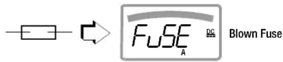
Replacing the Fuse
If a fuse should blow, eliminate the cause of overload before placing the instrument back into service!

Attention!
Disconnect the instrument from the measuring circuit before opening the fuse cover in order to replace the fuse!
Set the instrument face down onto the working surface.
Turn the slotted screw on the cover with the fuse symbol counterclockwise.
- Lift off the cover and pry the fuse out using the flat side of the fuse cover.
Insert a new fuse. Make sure that the fuse is centered, i.e. between the tabs at the sides.
When replacing the fuse cover, insert the side with the guide hooks first.
Tighten the screw by turning it clockwise.
→Dispose of the blown fuse with the trash.

Attention!
Use specified fuses only!
If fuses with other blowing characteristics, other current ratings or other breaking capacities are used, the operator is placed in danger, and protective diodes, resistors and other components may be damaged.
The use of repaired fuses or short-circuiting the fuse holder is prohibited.

Note
Testing the Fuse with the Instrument Switched On
After inserting the fuse with the instrument switched on, the instrument must be switched off briefly and then switched back on, or briefly switched to a non-current measuring range and then back to the "A" measuring range. If contact is poor or the fuse is blown, FUSE appears at the display.
9.4 Housing Maintenance
No special maintenance is required for the housing. Keep outside surfaces clean. Use a slightly dampened cloth for cleaning. Avoid the use of cleansers, abrasives or solvents.
9.5 Return and Environmentally Sound Disposal
The instrument is a category 9 product (monitoring and control instrument) in accordance with ElektroG: German electrical and electronic device law). This device is subject to the RoHS directive. Furthermore, we make reference to the fact that the current status in this regard can be accessed on the Internet at www.gossenmetrawatt.com by entering the search term WEEE.
We identify our electrical and electronic devices in accordance with WEEE 2012/19/EU and ElektroG with the symbol shown at the right per DIN EN 50419.

These devices may not be disposed of with the trash.
Please contact our service department regarding the return of old devices (see page 4).
If you use batteries or rechargeable batteries in your instrument or accessories which no longer function properly, they must be duly disposed of in compliance with the applicable national regulations.
Batteries or rechargeable batteries may contain harmful substances or heavy metal such as lead (PB), cadmium (CD) or mercury (Hg).
They symbol shown to the right indicates that batteries or rechargeable batteries may not be disposed of with the trash, but must be delivered to collection points specially provided for this purpose.

9.6 Recalibration
The respective measuring task and the stress to which your measuring instrument is subjected affect the ageing of the components and may result in deviations from the guaranteed accuracy.
If high measuring accuracy is required and the instrument is frequently used in field applications, combined with transport stress and great temperature fluctuations, we recommend a relatively short calibration interval of 1 year. If your measuring instrument is mainly used in the laboratory and indoors without being exposed to any major climatic or mechanical stress, a calibration interval of 2-3 years is usually sufficient.
During recalibration* in an accredited calibration laboratory (DIN EN ISO/IEC 17025) the deviations of your instrument in relation to traceable standards are measured and documented. The deviations determined in the process are used for correction of the readings during subsequent application.
We are pleased to perform DAkkS or factory calibrations for you in our calibration laboratory. Please visit our website at www.gossenmetrawatt.com ( Company DAkkS Calibration Center or FAQs Calibration questions and answers).
By having your measuring instrument calibrated regularly, you fulfill the requirements of a quality management system per DIN EN ISO 9001.
* Verification of specifications or adjustment services are not part of the calibration. For products from our factory, however, any necessary adjustment is frequently performed and the observance of the relevant specification is confirmed.
9.7 Manufacturer's Guarantee
All METRA HIT digital multimeters and calibration instruments are guaranteed for a period of 3 years after date of shipment. The manufacturer's guarantee covers materials and workmanship. Damages resulting from use for any other than the intended purpose or operating errors, as well as any and all consequential damages, are excluded.
The calibration certificate confirms that the product conformed to the specified technical data at the time of calibration. We guarantee the observance of the specified technical data within the admissible tolerance limits for a period of 12 months from delivery.
Accessories
10 Accessories
10.1 General
The extensive accessories available for our measuring instruments are checked for compliance with currently valid safety regulations at regular intervals, and are expanded as required for new applications. Currently up-to-date accessories which are suitable for your measuring instrument are listed at the following web address along with photo, order number, description and, depending upon the scope of the respective accessory, data sheet and operating instructions: www.gossenmetrawatt.de (→ Products → Measuring Technology – Portable → Multimeters → METRAHIT ... → ↗ Accessories).
10.2 Technical Data for Measurement Cables Electrical Safety of KS17-2 safety cable set
| Maximum Rated Voltage 600 V | 1000 V | 1000 V | |
| Measuring Category | CAT IV | CAT III | CAT II |
| Maximum Rated Current | 1 A | 1 A | 16 A |
| with safety cap applied | • | • | — |
| without safety cap applied | — | — | • |
Please observe the maximum values of the electrical safety of the instrument.
Electrical Safety of KS17-2AMB safety cable set (with antimicrobial properties, supply only with SECULIFEHITAM)
| Maximum Rated Voltage 300 V | 600 V | 600 V | |
| Measuring Category | CAT IV | CAT III | CAT II |
| Maximum Rated Current | 1 A | 1 A | 16 A |
| with safety cap applied | • | • | — |
| without safety cap applied | — | — | • |
Please observe the maximum values of the electrical safety of the instrument.
Ambient Conditions (EN 61010-031)
Temperature-20°C ... + 50°C
Relative humidity 50 to 80%
Pollution degree 2
Application KS17-2/KS17-2AMB

Attention!
Please observe the maximum values of the electrical supply of the device.
In conformity with standard DIN EN 61010-031, measurements in an environment according to measuring category III and IV may only be performed with the safety cap applied to the test probe of the measurement cable.
For establishing contact in 4 mm jacks you have to remove the safety cap by levering out the snap lock of the safety cap with another sharp object (e.g. the second test probe).
10.3 NA X-TRA Power Pack (not included)
Use only the power pack from GMC-I Messtechnik GmbH in combination with your instrument. This assures operator safety by means of an extremely well insulated cable, and safe electrical isolation (nominal secondary ratings: 5 V / 600 mA). Installed batteries are disconnected electronically if the power pack is used, and need not be removed from the instrument.
10.4 Interface Accessories for METRAHIT X-TRA/OUTDOOR and SECULIFEHITAM/MD (not included)
USB X-TRA Bidirectional Interface Adapter
This adapter makes it possible to connect STARLINE multimeters which are equipped with a serial IR interface to the USB port at a PC. The adapter allows for data transmission between the multimeter and the PC.
METRAwin 10 PC Analysis Software
METRAwin 10 PC software is a multilingual, measurement data logging program* for recording, visualizing, evaluating and documenting measured values from METRA HIT multimeters.
Details on the system requirements are given in the installation instructions of METRAwin 10/METRAwin 45.
* runs under any IBM compatible Windows operating system
Index
11 Index
Numerics
0.diSP 48
A
A.diSP 49
Addr 53
APoFF 49
Automatic Shutdown
Disabling 17
Specifying a Time 17
AUTO-Range Function 18
B
bAtt 48
Batteries
Charge Level 62
Charging Level 13
Periods of Non-Use 62
Replacement 63
bEEP 49
C
Cable Resistance 37
Capacitance Measurement 38
Clear Memory 24
Clip-On Current Sensor 42, 43
Clip-On Current Transformer 44
Continuity Test 34
Current Measurement
Notes 39
Scope of Functions 39
D
dAtE 48,50
Default Settings 50
Diode Test 35
Display Illumination ....16
Duty Cycle Measurement 32
E
Error Messages 62
F
Fuse Characteristic Values ....59
H
Housing Maintenance 64
|
Interfaces Accessories ....67 States ....13
irStb 53
itEMP 48
M
Manufacturer's Guarantee 65
Measured Value Storage DATA Function ....21 Min-Max Values ....22
Measurement Cables 66
Measuring Category Characteristic Values ....59 Significance ....8
Measuring Range Selection
Automatic 18
Manual 18
Memory
Ending Recording 24
Querying Occupancy 24
Start Recording 23
0
OCCUP 48
Overview
Keys and Connections 12
Parameters 47
P
Power Pack Accessories 66
Connector Socket Position 15
Initial Start-Up 16
Product Support 3
Product Support Hotline 3
R
rAtE 48
Recalibration Service 4, 65
Remote 36
Repair and Replacement Parts Service 4
Replacing the Fuse 63
Resistance Measurement 33
Return of Old Devices 64
S
Safety Precautions 8
Software Enabling ....3
Standard Equipment 2
Switching the Instrument On
Manual 16
Via PC 16
Symbols
Digital Display 13
Instrument 15
Rotary Switch Positions 14
T
Temperature Measurement
With Resistance Thermometers .....37
With Thermocouples ....36
tiME 48,50
U
Use for Intended Purpose 10
V
vErSion 48
Voltage Comparator 29,31
Voltage Measurement
Notes 26
Scope of Functions 26
W
WEEE Mark 15
Edited in Germany • Subject to change without notice • A pdf version is available on the internet
GOSSEN METRAWATT