
DW7350 - Planer DEWALT - Free user manual and instructions
Find the device manual for free DW7350 DEWALT in PDF.

| Product type | Mobile stand for planer |
| Brand | DeWalt |
| Model | DW7350 |
| Category | Planer |
| Frame material | Steel |
| Tablet material | MDF (medium-density fiberboard) |
| Maximum load capacity | 136 kg (300 lb) |
| Approximate dimensions (assembled) | Approximately 70 x 60 x 80 cm |
| Approximate weight | Approximately 25 kg |
| Power supply | Not applicable (passive stand) |
| Main functions | Stable support for planer, movement on swivel casters, adjustable height via rubber feet |
| Compatible planers | DeWalt DW733, DW734, DW735 |
| Number of casters | 4 swivel casters |
| Lifting/locking pedal | Yes, integrated |
| Maintenance and cleaning | Clean with a damp cloth and mild soap; do not use solvents |
| Safety | ANSI Z87.1 eye protection recommended; do not stand on the table; use on a flat and stable surface |
| Spare parts and repairability | Use only identical DeWalt replacement parts; repairs by authorized center |
| General information | Limited 3-year warranty, free 1-year service contract, 90-day money-back guarantee |
Frequently Asked Questions - DW7350 DEWALT
User questions about DW7350 DEWALT
0 question about this device. Answer the ones you know or ask your own.
Ask a new question about this device
Download the instructions for your Planer in PDF format for free! Find your manual DW7350 - DEWALT and take your electronic device back in hand. On this page are published all the documents necessary for the use of your device. DW7350 by DEWALT.
USER MANUAL DW7350 DEWALT
Check the contents of your planer stand carton to make sure you received all the parts. In addition to this instruction sheet, the carton should contain:
COMPONENTS
A. Long base rails
B. Short base rails
C. Pivot wheel assembly
D. Base wheels
E.Whool brackets
F. Rubber leveling feet
G. Legs
H. Short sides
Long sides
J. Support brackets
K.Shof
L MDF Top
HARDWARE INCLUDED
M. Cross head shoulder bolts (4)
N. 75 mm partially threaded hex bolts (4)
0.60 mm hex bolts (4)
P. 50 mm hex bolts (4)
Q. Short carriage bolts (30)
B. Lock washers (46)
S. Flat washers (4)
T.Nuts (48)
U. Lock nuts [2]
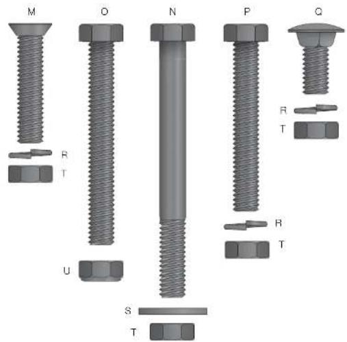
FIG.1
Definitions: Safety Guidelines
The definitions below describe the level of severity for each signal word. Please read the manual and pay attention to these symbols.
DANGER: Indicates an immmnly hazardous situation which, if not avoided, will result in death or serious injury.
WARNING: Indicates a potentially hazardous situation which, if not avoided, could result in death or serious injury.
CAUTION: Indicates a potentially hazardous situation which, if not avoided, may result in minor or moderate injury.
NOTICE: indicates a practice not related to personal injury which, if not avoided, may result in property damage.
IF YOU HAVE ANY QUESTIONS OR COMMENTS ABOUT THIS OR ANY Dr.WALT TOOL, CALL US TOLL FREE AT: 1-800-4-DeWALT (1-800-433-9258).

WARNING: To reduce the risk of injury, read the instruction manual.
Safety Rules andWarnings for Mobile Planer Stand
WARNING: Failure to follow these rules may result in serious personal injury.
- This product was designed to be used as a stand for planers. The stand will support up to 300 lbs (136 kg). Any misuse or abuse can result in product damage or personal injury.
- Do not stand on the work table. It is unsafe to climb, sit or stand on the stand. Do not use the support extensions as a ladder or scaffolding.
- Properly secure the planter to the stand before operation. Follow the mounting instructions carefully. Fasten the tool to the MOF tap securely as instructed.
- Place the stand on a flat and level surface to prevent rocking or tipping.
- Make sure the planer stand is firmly on the floor, the foot pedal is down and the wheel is raised before use.
- Do not modify or use the stand for any operation for which it is not intended.
- ALWAYS use eye protection. All users and bystanders must wear eye protection that conforms to ANSI Z87.1.
- ALWAYS use safety glasses. Every dayey eyeglasses are NOT safey glasses. Also use face or dust mask if cutting operation is dusty. ALWAYS WEAR CERTIFIED SAFETY EQUIPMENT:
ANSI Z87.1 eye protection (CAN/CSA Z94.3)
ANSI S12.6 (S3.19) hearing protection,
- NIOSH/OSHA/MSHA respiratory protection.
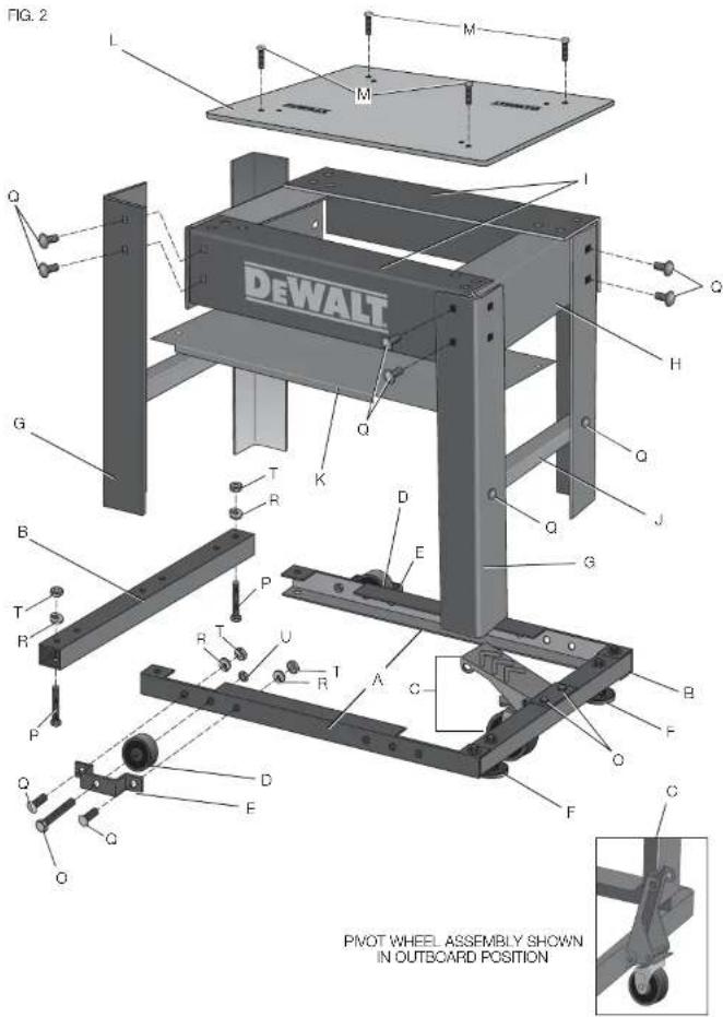
COMPONENTS (FIG. 1, 2)
AWARNING: Never modify the stand or any part of it. Damage or personal injury could result. Refer to Page 1 for a Components List.
ASSEMBLY AND ADJUSTMENTS (FIG. 1, 2)
WARNING: For your own safety, read the tool instruction manual before using any accessory. Failure to heed these warnings may result in personal injury and serious damage to the planer and the accessory. When servicing this tool, use only identical replace ment parts.
Recommended Tools for Assembly
- 13 mm open end wrench - Cross head screwdriver
- 13 mm socket and ratchet
Assemble the Frame Base and Attach Wheels
- Slide the short base rails (B) into the long base rails (A) and attach using the four 50 mm hex bolts (P). Each bolt should be fastened with a lock washer (R) and nut (T). Use 13 mm socket or wrench to tighten. This will give you the frame base.
- Attach the 2 wheel brackets (E) to the frame base using 2 carriage bolts (Q), 2 lock washers (R), and 2 nuts (T).
NOTE: The outside carriage bolt (Q) is used to attach the leg and wheel bracket to the base. It will need to be left off until the legs are attached.
- Align the base wheels (D) between the wheel bracket (E) and the long base rails.
-
Place the 60 mm hex bolt (O) through the holes in the bracket, wheel and long base rail until the threads protrude on the inside of the frame. Fasten the wheels to the base with a lock nut (U) until the nut is snug and the wheel turns freely.
-
Opposite the wheels, install the rubber leveling feet (F).
Attach the Pivot Wheel Assembly
The pivot wheel assembly (C) for your planer stand can be mounted inboard or outboard of the base.
- Align the holes on the pivot wheel assembly with the holes on the short base rails of the frame.
- Position the pivot wheel assembly (C) in the inboard or outboard position.
- Insert the two 60 mm hex bolts (O) through the holes in the pedal and the rails of the frame.
- Secure the pedal to the base by tightening the lock washers (R) and nuts (T) with a 13 mm socket and wrench.
CAUTION: When the pedal is in the outboard position on the stand, keep the mobile pliner stand out of walkways. Tripping and/or other personal injury may result.
Attach the Legs, Support Brackets and MDF Top
- Place the base frame in the upright position to attach the legs (G) to the corners using 4 carriage bolts (G). Tightly the nuts (T) and lock washers (R) with a 13mm socket or wrench.
2 Attach the short sides (H) to the inside of the legs (G) using 8 carriage bolts (Q), 8 lock washers (R), and 8 nuts (T). Use the socket or wrench to tighten. Be sure the holes in the sides are aligned with the locating drills provided. - Attach the long sides (I) to the inside of the legs (G), overlapping the short sides, using 8 carriage bolts (Q), 8 lock washers (R), and 8 nuts (T). Use the socket or wrench to tighten. Be sure the holes in the sides are aligned with the locating divots provided.
- Attach the side support brackets (J) to the inside middle of the legs (G) with 4 carriage bolts (Q), 4 lock washers (R) and 4 nuts (T). Use 13 mm socket or wrench to tighten.
- Attach the MDF top (L) to the sides (l) using the 4 cross head shoulder bolts (M), 4 each of the lock washers (R) and nuts (T).
Install the Shelf
- Lay the shelf (K), lip down, on top of the side support brackets.
- Insert 4 carriage bolts (Q) through the holes in the shelf and the side support brackets.
- Secure the shelf with lock washers (R) and nuts (T). Use 13 mm socket or wrench to tighten.
Attach the Planer to the Stand (Fig. 1, 3)
WARNING: STABILITY HAZARD. Refer to your tool manufacturer's instructions regarding the securing of your plainer to a stand or supporting surface. Secure the tool according to both the instructions in this manual and those in your tool manufacturer's manual before operating. Failure to heed these warnings may result in serious personal injury and serious damage to the tool.
WARNING: To reduce the risk of injury, turn planer off, disconnect the tool from the power source before assembling the planer to the stand. An accidental start-up can cause injury.
WARNING: For your own safety, it is recommended that two people carry this machine or serious injury could result.
Your planor stand is set up to accept the DW733, DW734 or DW735 DEWALT thickness planers.
- Carefully lift and place the planer on the MDF top (L).
- Align the holes in the planer base with corresponding holes on the MDF top.
- Insert four 75~mm hex head bolts (N) through the planer and base and secure them with the flat washers (S) and nuts (T) provided.
IF YOU DO NOT HAVE A DeWALT PLANER, BUT WISH TO USE THE DW7350 MOBILE PLANER STAND:
WARNING: Center your planer on the stand. Failure to center the planer could lead to an unstable assembly. Serious injury could result.
- Mark the placement of the holes on the MDF top (L).
- Drill marked holes in the MDF top.
- Attach your planer to the MDF top with the hex head bolts (N), flat
washers (S), and nuts (T) provided.
NOTE: Do not drill more than 4 holes. One bolt per corner is sufficient. Properly sized hardware (obtained locally) may be required to securely attach the planer if not DEWALT to the MDF top.
WARNING: Planners MUST be mounted in the orientation shown in
Figure 3
IMPORTANT: The planer MUST be positioned so the tool is bolted.
squaredly to the MDF top. If this is not possible, please call 1-800-4-DeWALT (1-800-433-9258) for technical assistance.
WARNING: Any tool used with this stand must be properly positioned and secured to ensure stability and to prevent inadvertent tipping.
To Adjust the Rubber Leveling Feet
The two rubber feet (F) of the mobile planer stand are installed for additional support on slightly uneven floors.
- Loosen the 2 nuts that hold one of the rubber feet of the mobile base.
- Grasp the nuts with a wrench and turn the foot until it is extended or retracted to the level required.
- Re-lighten the bolts.
- Repeat for the other rubber foot.
NOTE: Once assembly is complete and before first use, check each bolt and nut to ensure it is properly tightened, and that all mechanisms operate properly.
OPERATION
WARNING: To reduce the risk of serious personal injury, turn tool off and disconnect tool from power source before installing and removing accessories, before adjusting or changing set-ups or when making repairs. An accidental start-up can cause injury.
Make sure the planer stand is firmly on the floor, the foot pedal down and the wheel raised before use.
WARNING: Do not attempt to move the planer on the stand if the planer is not bolted down. Serious personal injury may result.

To Move Planer Stand
- Step on the foot pedal to unlock and lift stand.
- Firmly grasp the handles on your planer. Move to a new location.
- Push the foot pedal up, dropping the base into a locked position before you resume planing. CAUTION: Use caution when moving the planer stand. Tipping can occur if wheels are stopped abruptly by encountering debris on the floor or other irregularities in travel path.
MAINTENANCE
WARNING: To reduce the risk of injury, turn unit off and disconnect it from power source before installing and removing accessories, before adjusting or when making repairs. An accidental start-up can cause injury.
Cleaning
WARNING: Never use solvents or other harsh chemicals for cleaning the non-metallic parts of the tool. These chemicals may weaken the plastic materials used in these parts. Use a cloth dampened only with water and mild soap. Never let any liquid get inside the tool; never immerse any part of the tool into a liquid.
Accessories
WARNING: Since accessories, other than those offered by DeWALT, have not been tested with this product, use of such accessories with this tool could be hazardous. To reduce the risk of injury, only DeWALT recommended accessories should be used with this product.
Recommended accessories for use with your tool are available at extra cost from your local dealer or authorized service center. If you need assistance in locating any accessory, please contact Dr.WALT Industrial Tool Co., 701 East Joppa Road, Baltimore, MD 21286, call 1-800-4-Dr.WALT (1-800-433-9258) or visit our website: www.dewalt.com.
Repairs
To assure product SAFETY and RELIABILITY, repairs, maintenance and adjustment (including brush inspection and replacement) should be performed by a DEWALT factory service center, a DEWALT authorized service center or other qualified service personnel. Always use identical replacement parts.
Register Online
Thank you for your purchase. Register your product now for:
WARRANTY SERVICE: Registering your product will help you obtain more efficient warranty service in case there is a problem with your product.
CONFIRMATION OF OWNERSHIP: In case of an insurance loss, such as fire, flood or theft, your registration of ownership will serve as your proof of purchase.
FOR YOUR SAFETY: Registering your product will allow us to contact you in the unlikely event a safety notification is required under the Federal Consumer Safety Act.
Register online at www.dewalt.com/regisler.
Three Year Limited Warranty
DeWALT will repair, without charge, any defects due to faulty materials or workmanship for three years from the date of purchase. This warranty does not cover part failure due to normal wear or tool abuse. For further detail of warranty coverage and warranty repair information, visit www.dewalt.com or call 1-800-4-DeWALT (1-800-433-9258). This warranty does not apply to accessories or damage caused where repairs have been made or attempted by others. This warranty is the only warranty offered by DeWALT, and any implied warranties shall not apply. DeWALT will not be responsible for any incidental or consequential damages. This warranty gives you specific legal rights and you may have other rights which vary in certain states or provinces. Some states do not allow the exclusion or limitation of incidental or consequential damages, or limitations on how long an implied warranty lasts, so the above limitations or exclusions may not apply to you.

In addition to the warranty, DFWALT tools are covered by our:
1 YEAR FREE SERVICE
DeWALT will maintain the tool and replace worn parts caused by normal use, for free, any time during the first year after purchase.
90 DAY MONEY BACK GUARANTEE
If you are not completely satisfied with the performance of your DeWALT Power Tool, Laser, or Nailer for any reason, you can return it within 90 days from the date of purchase with a receipt for a full refund - no questions asked.
LATIN AMERICA: This warranty does not apply to products sold in Latin America. For products sold in Latin America, see country specific warranty information contained in the packaging, call the local company or see website for warranty information.
FREE WARNING LABEL REPLACEMENT: If your warning labels become illegible or are missing, call 1-800-4-D-WALT (1-800-433-9258) for a free replacement.
ETABLI MOBILE DE RABOTEUSE DW7350
J. Supports de fixation
Local D, Col. Obrera (55) 5588 9377
MEBIDA, YUC
Calle 63 #459-A-Col.Centro (999)928 5038
MONTERREY, N.L.
Av, Francisco I, Madero 831 Poniente - Col. Centro (818) 375 23 13
PUEBLA, PUE
17 Norte #205 - Col. Centro (222) 246 3714
QUERETARO, QRO
Av. San Roque 274-Col. San Gregorio (442) 2176314
SAN LUIS POTOSI, SLP
DeWALT Industrial Tool Co., 701 East Joppa Road, Baltimore, MD 21286
(JUN13) Part No. N320021 DW7350 Copyright © 2013 DEWALT
The following are trademarks for one or more DEWALT power tools: the yellow and black color scheme; the "D" shaped air intake grill; the array of pyramids on the handgrip; the kit box configuration; and the array of lozenge-shaped humps on the surface of the tool.


- COMPONENTS
- HARDWARE INCLUDED
- Definitions: Safety Guidelines
- Safety Rules andWarnings for Mobile Planer Stand
- COMPONENTS (FIG. 1, 2)
- ASSEMBLY AND ADJUSTMENTS (FIG. 1, 2)
- Recommended Tools for Assembly
- Assemble the Frame Base and Attach Wheels
- Attach the Pivot Wheel Assembly
- Attach the Legs, Support Brackets and MDF Top
- Install the Shelf
- Attach the Planer to the Stand (Fig. 1, 3)
- IF YOU DO NOT HAVE A DeWALT PLANER, BUT WISH TO USE THE DW7350 MOBILE PLANER STAND:
- To Adjust the Rubber Leveling Feet
- OPERATION
- To Move Planer Stand
- MAINTENANCE
- Cleaning
- Accessories
- Repairs
- Register Online
- Three Year Limited Warranty
- YEAR FREE SERVICE
- DAY MONEY BACK GUARANTEE
- ETABLI MOBILE DE RABOTEUSE DW7350
- MONTERREY, N.L.
- PUEBLA, PUE
- SAN LUIS POTOSI, SLP
Brand : DEWALT
Model : DW7350
Category : Planer