ST 430T - Snow blower HUSQVARNA - Free user manual and instructions
Find the device manual for free ST 430T HUSQVARNA in PDF.
User questions about ST 430T HUSQVARNA
0 question about this device. Answer the ones you know or ask your own.
Ask a new question about this device
Download the instructions for your Snow blower in PDF format for free! Find your manual ST 430T - HUSQVARNA and take your electronic device back in hand. On this page are published all the documents necessary for the use of your device. ST 430T by HUSQVARNA.
USER MANUAL ST 430T HUSQVARNA
Transportation, storage and disposal 28
Assembly. 8
Technical data. 29
Operation 11
EC Declaration of Conformity 30
Maintenance. 16
Introduction
Product overview
- Fuel tank cap
- Muffler
- Oil fill/dipstick (for ST 424T/427T/430T only)
- Battery cover
- Discharge chute lever
- Auger engagement
- Drive speed lever
- Control panel
- Remote control lever
- Drive engagement
- Steering triggers
- Handle knobs
13.Wheel (for ST 424/427/430 only) -
Dipstick (for ST 424/427/430 only)
-
Oil fill (for ST 424/427/430 only)
- Oil drain
- Starter rope handle
- Fuel ON/OFF switch (for ST 424/427/430 only)
- Primer (for ST 424/427/430 only)
- Continuous track (for ST 424T/427T/430T only)
- Auger bucket
- Skid plate
- Augers
- Tool for cleaning
- Discharge chute
- Discharge chute deflector
- LED light
Product overview
- Adjustment lever for the auger bucket
- ON/OFF switch for the heated grip
- Hour meter and oil change reminder
- Throttle
- Discharge chute lever
- Release lever
- Ignition slot
- Auger engagement
- Drive speed lever
-
Symbols label
-
Remote control lever for the discharge chute deflector
- Drive engagement
Product description
The product is a snow thrower that is used to remove snow from the ground.
Intended use
This product can be used to remove snow from fields, roads, walkways and driveways. Do not use it on slopes that are greater than 20^ . Do not use the product in areas where there is much debris, dirt and protruding stones.
Symbols on the product
Note: If the decals on the product are damaged, contact the distributor to replace them.

Warning.

Read the operator's manual.

Power on.
Start the engine.

Engine off.

Boost.

Fast.

Slow.

Oil change reminder.

Heated handles.
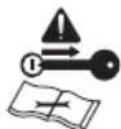
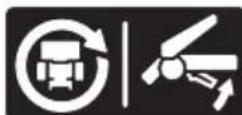
Remove key before maintenance.

Hot surface.

Risk of fire.
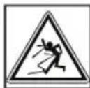
Beware of thrown objects.

Keep bystanders away.

Do not breathe in exhaust fumes.

Move slowly rearward.
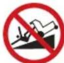
Risk of falling.

Turn left.
Turn right.

Throw snow.
Change auger bucket height.
Product liability
As referred to in the product liability laws, we are not liable for damages that our product causes if:
- the product is incorrectly repaired.
- the product is repaired with parts that are not from the manufacturer or not approved by the manufacturer.
- the product has an accessory that is not from the manufacturer or not approved by the manufacturer.
- the product is not repaired at an approved service center or by an approved authority.
Safety
Safety definitions
The definitions below give the level of severity for each signal word.

WARNING: Injury to persons.

CAUTION: Damage to the product.
Note: This information makes the product easier to use.
General safety instructions
- Use the product correctly. Injury or death is a possible result of incorrect use. Only use the product for the tasks found in this manual. Do not use the product for other tasks.
- Obey the instructions in this manual. Obey the safety symbols and the safety instructions. If the operator does not obey the instructions and the symbols, injury, damage or death is a possible result.
- Do not discard this manual. Use the instructions to assemble, to operate and to keep your product in good condition. Use the instructions for correct installation of attachments and accessories. Only use approved attachments and accessories.
- Do not use a damaged product. Obey the maintenance schedule. Only do the maintenance work that you find an instruction about in this manual. An approved service center must do all other maintenance work.
- This manual cannot include all situations that can occur when you use the product. Be careful and use your common sense. Do not operate the product or do maintenance to the product if you are not sure about of the situation. Speak to a product expert, your dealer, service agent or approved service center for information.
- Disconnect the spark plug cable before you assemble the product, put the product into storage or do maintenance.
- Do not use the product if it is changed from its initial specification. Do not change a part of the product without approval from the manufacturer. Only use parts that are approved by the manufacturer. Injury or death is a possible result of incorrect maintenance.
- Do not breathe in the fumes from the engine. Long term inhalation of the engine's exhaust fumes is a health risk.
- Do not start the product indoors or near flammable material. The exhaust fumes are hot and can contain
a spark which can start a fire. Not sufficient airflow can cause injury or death because of asphyxiation or carbon monoxide.
- When you use this product the engine makes an electromagnetic field. The electromagnetic field can cause damage to medical implants. Speak to your physician and medical implant manufacturer before you operate the product.
- Do not let a child operate the product. Do not let a person, without knowledge of the instructions operate the product.
- Make sure that you always monitor a person, with decreased physical capacity or mental capacity, that uses the product. A responsible adult must be there at all times.
- Lock the product in an area that children and unapproved persons cannot access.
- The product can eject objects and cause injuries. Obey the safety instructions to decrease the risk of injury or death.
- Do not go away from the product when the engine is on.
- The operator of the product is responsible if an accident occurs.
- Before and while you walk rearward, look behind and down for small children, animals or other risks that can cause you to fall.
- Make sure that parts are not damaged before you use the product.
- Make sure that you are at a minimum 15m (50 ft) away from other persons or animals before you use the product. Make sure that a person in adjacent area knows that you will use the product.
- Refer to national or local laws. They can prevent or decrease the operation of the product in some conditions.
Safety instructions for operation
- Do not put hands or feet near or under rotating parts. Keep clear of the discharge opening at all times.
- Exercise extreme caution when operating on or crossing gravel drives, walks, or roads. Stay alert for hidden hazards or traffic.
After striking a foreign object, stop the engine (motor), remove the wire from the spark plug, disconnect the cord on electric motors, thoroughly inspect the product for any damage, and repair the damage before restarting and operating the product. - If the product starts to vibrate abnormally, stop the engine (motor) and check immediately for the cause. Vibration is generally a warning of trouble.
-
Stop the engine (motor) whenever you leave the operating position, before unclogging the auger housing or chute deflector, and when making any repairs, adjustments or inspections.
-
When cleaning, repairing or inspecting the product, stop the engine and make certain the augers and all moving parts have stopped. Disconnect the spark plug wire and keep the wire away from the plug to prevent someone from accidentally starting the engine.
- Do not run the engine indoors, except when starting the engine and for transporting the product in or out of the building. Open the outside doors; exhaust fumes are dangerous.
Exercise extreme caution when operating on slopes. - Never operate the product without proper guards, and other safety protective devices in place and working.
- Never direct the chute deflector toward people or areas where property damage can occur. Keep children and others away.
- Do not overload the product capacity by attempting to clear snow at too fast a rate.
- Never operate the product at high transport speeds on slippery surfaces. Look behind and use care when operating in reverse.
- Disengage power to the augers when the product is transported or not in use.
- Use only attachments and accessories approved by the manufacturer of the product (such as wheel weights, counterweights, or cabs).
- Never operate the product without good visibility or light. Always be sure of your footing, and keep a firm hold on the handles. Walk; never run.
- Never touch a hot engine or muffler.
Work area safety
- Thoroughly inspect the area where the equipment is to be used and remove all doormats, sleds, boards, wires, and other foreign objects.
- Disengage all clutches and shift into neutral before starting the engine (motor).
- Do not operate the product without wearing adequate winter garments. Avoid loose fitting clothing that can get caught in moving parts. Wear footwear that will improve footing on slippery surfaces.
-
Handle fuel with care; it is highly flammable.
-
Use an approved fuel container.
- Never add fuel to a running engine or hot engine.
- Fill fuel tank outdoors with extreme care. Never fill fuel tank indoors.
- Never fill containers inside a vehicle or on a truck or trailer bed with a plastic liner. Always place containers on the ground, away from your vehicle, before filling.
-
When practical, remove gas-powered equipment from the truck or trailer and refuel it on the ground. If this is not possible, then refuel such equipment on a trailer with a portable container, rather than from a gasoline dispenser nozzle.
-
Keep the nozzle in contact with the rim of the fuel tank or container opening at all times, until refueling is complete. Do not use a nozzle lock-open device.
- Replace gasoline cap securely and wipe up spilled fuel.
-
If fuel is spilled on clothing, change clothing immediately.
-
Use extension cords and receptacles as specified by the manufacturer for all units with electric drive motors or electric starting motors.
- Adjust the auger housing height to clear gravel or crushed rock surface.
- Never attempt to make any adjustments while the engine (motor) is running (except when specifically recommended by the manufacturer).
- Always wear safety glasses or eye shields during operation or while performing an adjustment or repair to protect eyes from foreign objects that may be thrown from the machine.
Personal protective equipment
Always use the correct personal protective equipment when you operate the product. This includes, at minimum, sturdy footwear, eye protection and hearing protection. Personal protective equipment does not erase the risk of injury but may decrease the grade of injury if an accident occurs.
- Always wear safety glasses or eye protection while you operate the product or do maintenance or repairs.
- Always wear appropriate winter garments when you operate the product.
- Always use heavy-duty slip-resistant boots with good ankle support while you operate the product.
- Do not wear loose fitting clothing that can get caught in moving parts.
- Use approved protective gloves, if necessary. For example, when attaching, examining or cleaning the blade.
- Always use approved ear protection while you operate the product. Noise for a long period can cause noise-induced hearing loss.
Safety devices on the product
-
Make sure that you regularly do the maintenance to the product.
-
The life of the product increases.
- The risk of accidents decreases.
Let an approved dealer or an approved service center regularly examine the product to do adjustments or repairs.
- Do not use a product with damaged protective equipment. If the product is damaged, speak to an approved service center.
Muffler
The muffler keeps the noise levels to a minimum and sends the exhaust fumes away from the operator.
Do not use the product if the muffler is missing or defective. A defective muffler increases the noise level and the risk of fire.
Examine the muffler regularly to make sure that it is attached correctly and not damaged.

CAUTION: The muffler becomes very hot during and after use and when the engine operates at idle speed. Be careful near flammable materials and/or fumes to prevent fire.
Fuel safety

WARNING: Read the warning instructions that follow before you use the product.
- Do not start the product if there is fuel or engine oil on the product. Remove the unwanted fuel/oil and let the product dry.
If you spill fuel on your clothing, change clothing immediately. - Do not get fuel on your body, it can cause injury. If you get fuel on your body, use soap and water to remove the fuel.
- Do not start the product if the engine has a leak.
Examine the engine for leaks regularly. - Be careful with fuel. Fuel is flammable and the fumes are explosive and can cause injuries or death.
- Do not breathe in the fuel fumes, it can cause injury.
Make sure that there is a sufficient airflow. - Do not smoke near the fuel or the engine.
- Do not put warm objects near the fuel or the engine.
- Do not add the fuel when the engine is on.
- Make sure that the engine is cool before you refuel.
- Before you refuel, open the fuel tank cap slowly and release the pressure carefully.
- Do not add fuel to the engine in an indoor area. Not sufficient airflow can cause injury or death because of asphyxiation or carbon monoxide.
- Tighten the fuel tank cap fully. If the fuel tank cap is not tightened, there is a risk of fire.
- Move the product a minimum of 3m (10 ft) from the position where you filled the tank before a start.
- Do not put too much fuel in the fuel tank.
Battery safety

WARNING: A damaged battery can cause an explosion and cause injury. If the battery
has a deformation or is damaged, speak to an approved Husqvarna service agent.

WARNING: Read the warning instructions that follow before you use the product.
- Use protective glasses when you are near batteries.
- Do not wear watches, jewelry or other metal objects near the battery.
- Keep the battery out of reach for children.
- Charge the battery in a space with good airflow.
- Keep flammable materials at a minimum clearance of 1m when you charge the battery.
- Discard replaced batteries. See Disposal on page 29.
- Explosive gases can come from the battery. Do not smoke near the battery. Keep the battery away from open flames and sparks.
Safety instructions for maintenance

WARNING: Read the warning instructions that follow before you use the product.
- The exhaust fumes from the engine contain carbon monoxide, an odorless, poisonous and very dangerous gas. Do not start the engine indoors or in closed spaces.
- Before you do the maintenance on the product, stop the engine and remove the ignition cable from the spark plug.
- Use protective gloves when you do maintenance on the blades. The blades are very sharp and cuts can easily occur.
- Accessories and changes to the product that are not approved by the manufacturer, can cause serious injury or death. Do not change the product. Always use accessories that are approved by the manufacturer.
If the maintenance is not done correctly and regularly, the risk of injury and damage to the product increases. - Only do the maintenance as given in this operator's manual. All other servicing must be done by an approved service agent.
- Let an approved service agent do servicing on the product regularly.
- Replace damaged, worn or broken parts.
Assembly
To remove the product from the carton
- Remove loose parts included with the product. Cut the four corners of the carton and put the end panels down flat.
- Remove the two screws that attach the auger housing to the pallet. Remove the steel brackets from the skid plates if they have it.
- Remove all package materials.
- Remove the product from the carton and make sure no loose parts are left in the carton.
Loose parts
Discharge chute (1)
ON/OFF key (s)
Carriage bolts 5 / 16 - 18 × 214'' (2)
Chute retainer

Handle knobs (2)

Locknut 3/8 (1)

Locknut 3/18-16 (1)
(ST 424/427/430) Cable holder (1)

Shear pins 1 / 4 - 20 × 1.81 (6)

Locknuts 1 / 4 - 20 (6)

Locknut 5/16-18 (1)

Locknut 1 / 4 - 20 (1)

Nylon washer (1)
Carriage bolt 5/16-18 x 5/8 (1)
Roll pin (1)
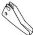
Release lever (1)
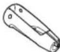
Discharge chute lever

Spring (1)
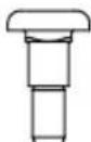
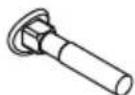
Shoulder bolt 1 / 4 - 20 (1)
Tools required
- 3/8 in. wrench (1)
- 7/16 in. wrench (1)
- 1/2 in. wrench (1)
9/16 in. deep socket (1)
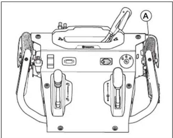
To install the handle
- Lift the upper handle to the operation position.
- Adjust the handle position to one of the holes (C).
- Put the bolt (B) through the hole (C).
- Attach the knob (A) to the bolt and tighten the knob.
- Attach more carriage bolts (B) and handle knobs (A) to attach the upper handle to the lower handle.
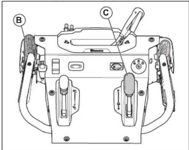
To install the discharge chute
- Put the deflector assembly for the discharge chute on the top of the discharge chute. The discharge opening must point to the front of the product.
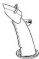
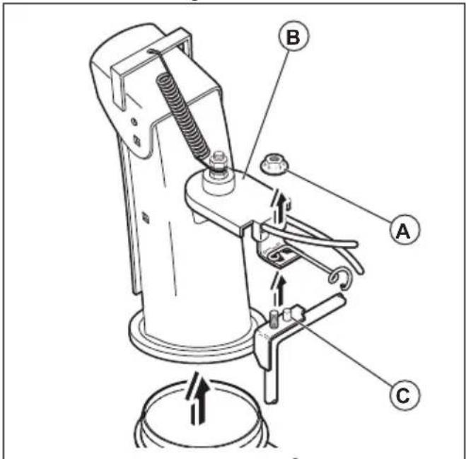
- Put the rotator head (A) on the discharge chute bracket (J).
-
Align the pins below the rotator head with the holes in the discharge chute bracket.
-
Put the rotator head on the pin (E), and the threaded stud (G) on the bracket (E).
- Attach a locknut (B) on the threaded stud and tighten.
- Attach the square retainer (I) with a locknut (H).
- For ST 424/427/430 only: Put the cables through the cable holder (C)
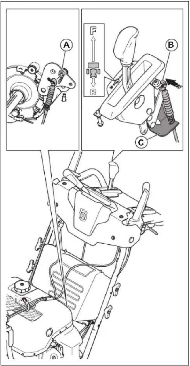
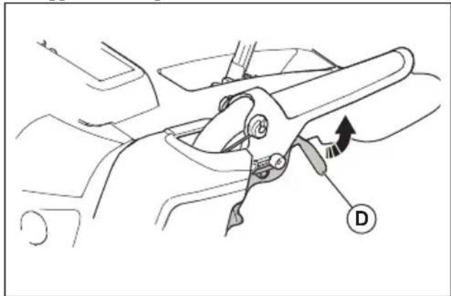
To install the discharge chute lever and the release cable
- Push the knob (D) down on the discharge chute lever. Use a rubber mallet if it is necessary.
- Attach the release cable to the discharge chute lever at connection (A).
- Put the release cable in the groove (B) on the discharge chute lever.
- Install the cable barrel fitting (F) to the release lever (E).
-
Install the release lever (E) to the discharge chute lever and attach it with the roll pin (C).
-
Adjust the release cable. See To adjust the release cable of the discharge chute on page 24.
- Adjust the left and right discharge chute cables. See To adjust the left and right discharge chute cables on page 24.
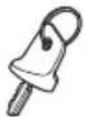
To install the remote control for the discharge chute deflector
- Attach the cable bracket (A) to the discharge chute with a carriage bolt (B) and a 5/16-18 locknut (D). Tighten the bolt.
- Install the cable eyelet (E) to the discharge chute deflector (F). Use a shoulder bolt (G), a nylon washer (C), and tighten with a 1/4 - 20 locknut (K). The cable eyelet will be loose on the shoulder bolt.
- Attach the spring (L) between the hex nut (M) on the rotator head and the hole on the discharge chute deflector.
To install the speed control cable
- Put the drive speed lever in the neutral position.
- Attach the speed control cable (B) to the drive speed lever with a retaining pin.
-
Attach the speed control cable to the bracket (C) with 212 in wrenches. Make sure that the drive speed lever stays in the neutral position.
-
Remove the screw and wing nut (A) on the bellcrank to let the bellcrank move.
To attach replacement shear pins
- Attach the replacement shear pins on the cover of the remote control or on the battery box.
Operation
Before you start the product
- Keep persons and animals away from the work area.
- Do daily maintenance. See Maintenance schedule on page 16.
- Make sure the ignition lead fits correctly on the spark plug.
- Add oil or gasoline, if necessary. See To fill fuel on page 11.
To fill the engine with oil

CAUTION: Do not rotate the dipstick when you check the oil. Do not fill above the mark.
- Remove the oil cap and clean the dipstick. See Product overview on page 2 for the location of the dipstick.
- Add oil to the top mark on the dipstick. Use the dipstick to do a check of the oil level at regular intervals.
- Put the oil cap back.
To fill fuel
If available, use low-emission/alkylate gasoline. If low-emission/alkylate gasoline is not available, use good quality unleaded gasoline or leaded gasoline. Use gasoline with an octane number of 90 RON out of North
America (87 AKI in North America) or higher, and with a maximum of 10% ethanol (E10).

CAUTION: Do not use gasoline with an octane number less than 90 RON out of North America (87 AKI in North America). This can cause damage to the product.
- Open the fuel tank cap slowly to release the pressure.
- Fill slowly with a fuel can. If you spill fuel, remove it with a cloth and let remaining fuel dry off.
- Clean the area around the fuel tank cap.
- Tighten the fuel tank cap fully. If the fuel tank cap is not tightened, there is a risk of fire.
- Move the product a minimum of 3m (10 ft) from the position where you filled the tank, before a start.
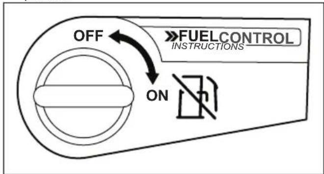
To use the fuel switch (for ST 424/427/430 only)
- Turn the fuel switch to open or close the fuel valve. Operate the product with the fuel switch in the OPEN position.
To start the engine, manual start
- Put the ON/OFF key into the ignition slot (B). Do not turn the key.

- For ST 424/427/430 only: Turn the fuel ON/OFF switch (C) to the ON position.
-
Put the throttle control (A) to the FAST position.
-
Turn the ON/OFF key to the ON position.
- For ST 424/427/430 only: If the temperature is lower than -17^ (0°F), push the primer 3 times. See Product overview on page 2 for primer position.

CAUTION: Do not push the primer too many times. It can prevent the engine from starting. If the engine is flooded, wait some minutes before you try to start. Do not push the primer.
- Pull the starter rope handle (D).

CAUTION: Do not release the starter rope handle quickly. Move it slowly to the start position.
Note: If the starter rope is frozen, slowly pull out as much rope out of the starter as you can. Release the starter rope handle. If the engine does not start, do the procedure again or use the electric starter.
- Run the engine 2-3 minutes at very low speed before you start to throw snow.
- If the engine does not run smoothly, turn it off.
To start the engine, electric start
- Put the ON/OFF key into the ignition slot (B). Do not turn the key.
- For ST 424/427/430 only: Turn the fuel ON/OFF switch (C) to the ON position.
- Put the throttle control (A) to the FAST position.
- Put the ON/OFF key to the ON position.
- For ST 424/427/430 only: If the temperature is lower than -17^ (0°F), push the primer 3 times. See Product overview on page 2 for primer position.

CAUTION: Do not push the primer too many times. It can prevent the engine from starting. If the engine is flooded, wait some minutes before you try to start. Do not push the primer.
- Turn the ON/OFF key to START. When the engine starts, release the key.

CAUTION: Do not run the starter for more than 5 seconds each time you try to start. Wait 5 to 10 seconds between each try.
- Run the engine 2-3 minutes at very low speed before you start to throw snow.
To operate the product

CAUTION: Do not partially engage drive or auger levers for an extended period of time; this can lead to premature wear or burning of the belts.
Note: When both the drive engagement and auger engagement are engaged, the drive engagement will lock the auger engagement in position. Use the right hand to control the snow discharge chute.
- To engage the auger blades, push the auger engagement (A) to the handle to engage the auger and throw snow.
-
Raise the drive speed control lever (C) from the middle position to make the product move forward when the drive engagement (B) is engaged.
-
Lower the drive speed control lever from the middle position to make the product move rearward when the drive engagement is engaged.
- To make the product move in the selected direction, hold the drive engagement against the handle.
- If the product has power steering, hold the left steering trigger (D) to turn left. Hold the right steering trigger to turn right.
Throttle control
Note: If the snow is wet or heavy, use the fast or boost modes.
The throttle control adjusts the engine speed. It has 3 modes: boost, fast and slow.
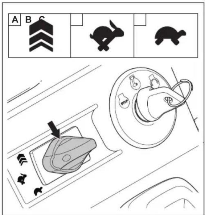
- Boost (A): to increase speed when the product is operated but does not throw snow, or to increase the distance that snow is thrown.
- Fast (B): standard operation
- Slow (C): to decrease the distance that snow is thrown, or to decrease engine noise
To use the throttle control
- Turn the throttle control to change the engine speed.
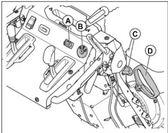
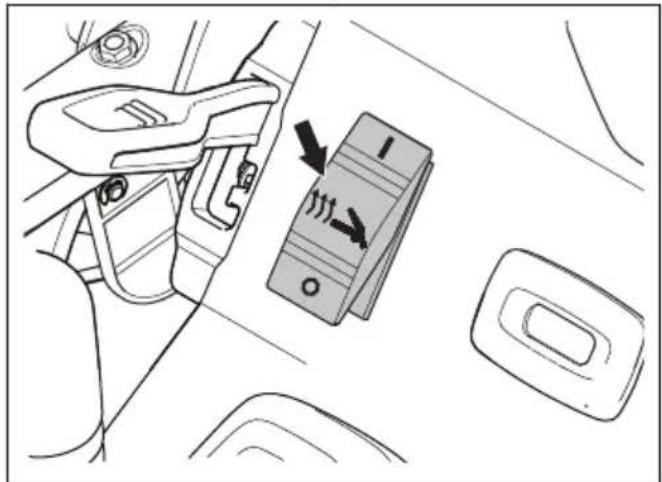
To use the heated handles
- Push the switch to I to start the heated handles.
- Push the switch to O to stop the heated handles.
To stop the product
- Turn the key to the STOP position.
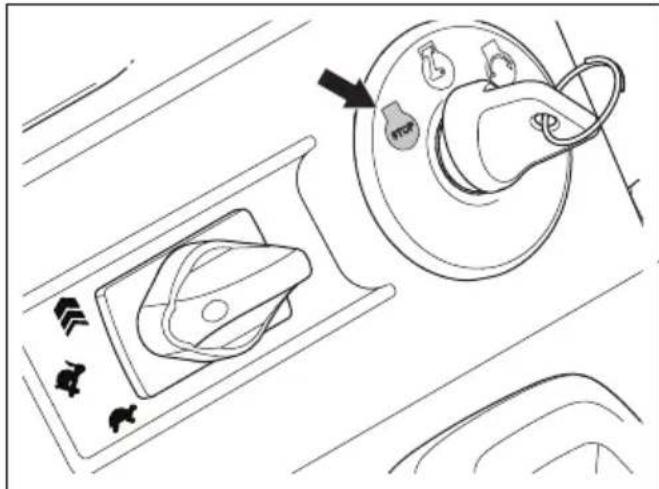
- Remove the ON/OFF key.
To adjust the discharge chute and the discharge chute deflector
- Push the release lever (B) on the discharge chute lever (A) and adjust the discharge chute to the left or right position.
- Move the remote control lever (C) to adjust the snow throwing distance.
a) Move the remote control lever up to decrease the snow throwing distance.
b) Move the remote control lever down to increase the snow throwing distance.
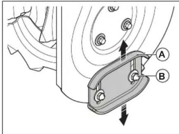
To adjust the skid plates
The skid plates prevent damage to the bottom of the snow thrower. Adjust the skid plates (A) when the locknut (B) is loose, or the skid plate is not at the correct distance from the ground. No adjustment is necessary for standard installation.
- Loosen the locknut (B) with a 13mm (1/2 in.) open wrench.
- Move the skid plates (A) up or down.
a) On flat surfaces set the distance between the scraper bar and the ground to 5-6 mm (0.2-0.25 in).
b) On rough surfaces set the skid plates (A) in a position where the scraper bar is above the top of the ground.

WARNING: Make sure that gravel and stones do not go into the product. Objects that eject at high speed can cause injury.
3. Tighten the locknut (B).
To use the drift cutters (if equipped)
Use the drift cutters to cut through snowdrifts deeper than the front of the product.
- Loosen the adjustment nuts (A) on both sides of the product to allow each drift cutter (B) to be raised to its highest position.
- Tighten the nuts.
- Lower the drift cutters after use.
To adjust the height of the auger bucket (for ST 424T/427T/430T only)
- Push the lever (A) down.
- Move the handles (B) up or down to adjust the height of the auger bucket.
- Release the lever (A) to lock the auger bucket in position.
Note: The auger bucket can be set to an unlocked position. This lets the auger bucket adapt to the terrain. To set the auger bucket to the unlocked position, push the lever (A) down and to the right.
To prevent freeze-up after use
Note: Controls and moving parts can be blocked by ice. Do not apply much force to the controls. If you cannot operate a control or a part, start the engine and let it operate for some minutes.
- Start the engine and let it operate for some minutes. Stop the engine and wait for all moving parts to stop.
- Remove snow and loose ice from the product.
- Remove snow and loose ice from the base of the discharge chute.
- Turn the discharge chute deflector to the left direction and to the right direction to remove ice and water.
- Set the key to the "OFF" position.
- If the product does not have an electric starter, pull the starter rope handle several times to remove ice and water.
To get a good result
Always run the engine at full throttle or near full throttle.
- Always adapt the speed of the product to the snow situation and adjust the speed with the drive speed control lever. Make sure that the product throws snow evenly.
- It is easier and more efficient to remove snow immediately after it falls.
- Always throw snow downwind whenever possible.
-
On flat surfaces, like asphalt roads, raise the skid plates up to 5-6 mm (0.2-0.25 in) off the ground.
-
The scraper bar is reversible. When it becomes worn almost to the edge of the housing, reverse it. Replace the scraper bar if it is damaged, or if both sides are worn.
- Do not dispatch the chute deflector if it is clogged.
- If the product does not move forward due to unforeseen circumstances, release the drive engagement immediately or move the ON/OFF key to the "OFF" position.
Maintenance
Introduction
When the product is in use, bolts can loosen and components can become worn. This can cause
malfunction like incorrect tolerance clearance, increased oil consumption, or misalignment of various components. Do regular maintenance on the product to prevent malfunction.
Maintenance schedule
| Maintenance Daily | At 15 hour inter-vals | At 20 hour inter-vals | At 40 hour inter-vals | At 100 hour inter-vals | |
| Tighten nuts and screws | X | ||||
| Do a check of the engine oil level | X | ||||
| Replace the engine oil | X | ||||
| Do a check of and adjust the track tension (only ST 424T/427T/430T) | X | ||||
| Make sure that there are no fuel or oil leaks | X | ||||
| Remove obstacles in the auger | X | ||||
| Lubricate the interlock catches1 | X | ||||
| Lubricate the cable attachments2 | X | ||||
| Do a check of the tire pressure (only ST 424/427/430)3 | X | ||||
| Inspect and replace the spark plug before use at the start of a season and at recommended interval | X |
Note: The gearbox does not need maintenance.
To do a general inspection
- Make sure that the nuts and screws on the product are tightened.
Oil change reminder
The oil change reminder (A) is a function that points out that an oil change is necessary. The oil change reminder lights up the oil can symbol on the display after 20 hours of operation. The oil can symbol is then on for 2 hours or until a manual reset is done.
To reset the oil change reminder
- Turn the ON/OFF key to the ON position, and keep it in the ON position for 1 second.
- Turn the ON/OFF key to the STOP position, and keep it in the STOP position for 1 second.
- Do this procedure 4 more times.
To do a check of the oil level

CAUTION: A too low oil level can do damage to the engine. Do a check of the oil level before you start the product.
- Put the product on level ground.
- Remove the oil tank cap with the attached dipstick.
- Clean the oil from the dipstick.
- Put the dipstick fully into the oil tank to give a correct picture of the oil level.
- Remove the dipstick.
-
Examine the oil level on the dipstick.
-
If the oil level is low, fill with engine oil and do a check of the oil level again.
To replace the engine oil
- Run the engine a few minutes to make the oil warm. Warm oil flows better and includes more contaminants.

WARNING: The engine oil is hot. Avoid skin contact with the used engine oil.
- Put the product on level ground.
- Remove the ON/OFF key.
- Put a container below the oil drain plug.
- Remove the oil drain plug, tip the product and drain the used oil in the container.
- Put the product back to the operating position.
- Install the oil drain plug and tighten it by hand.
- Fill the engine with oil, see To fill the engine with oil on page 11.
To lubricate the product
- Lubricate the pivot points (A) with oil.
- Lubricate the engine (B) with oil.
-
Lubricate the interlock catches (C) with a small quantity of lithium grease.
-
Lubricate the cable connections for the drive and auger levers (D) with oil.
Battery
Battery maintenance
Note: The battery on your product is maintenance free. Do not open or remove the caps or the covers.
To charge the battery
Note: Before long term storage, charge the battery with a battery charger to extend the life of the battery.
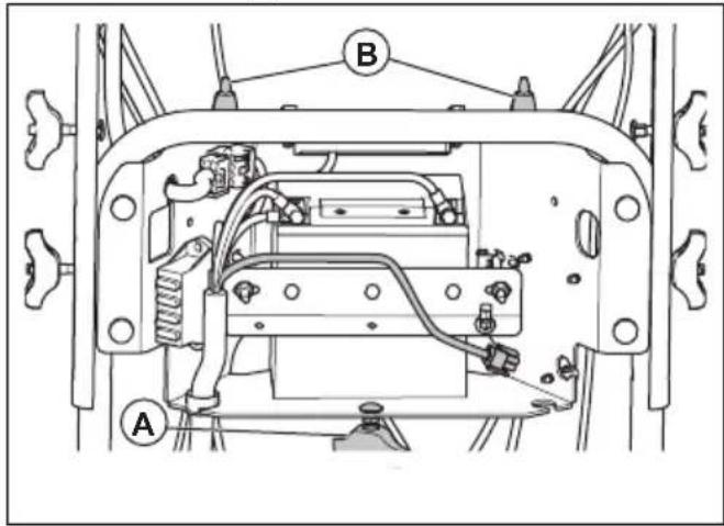
- Remove the battery cover. Refer to To replace the battery on page 18.
- Clean the terminals. Refer to To clean the battery and the terminals on page 18.
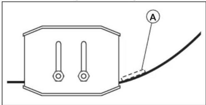
- Connect the battery charger to the battery charger connector (A).
- When the battery is charged, disconnect the battery charger.
- Install the battery cover.
To replace the battery

WARNING: Risk of electrical shock. Do not let metal objects touch the 2 battery terminals. This can cause a short circuit of the battery.
- Loosen the knob (A), then tilt the bottom of the cover in the direction of the engine. Lift the battery cover off the holders (B).
- Disconnect the BLACK battery cable.

WARNING: The BLACK cable must be disconnected first.
- Disconnect the RED battery cable.
- Loosen the nuts and remove the battery strap.
- Carefully remove the battery from the product.
- Install a new battery.
- Connect the RED battery cable and tighten the bolt.

WARNING: Risk of sparks. The RED cable must be connected first.
- Connect the BLACK cable and tighten the bolt.
- Install the battery cover.
To clean the battery and the terminals
- Remove the battery. Refer to To replace the battery on page 18.
- Flush the battery with plain water and let it become dry.
- Clean the terminals and battery cable ends with a wire brush until they are bright.
- Lubricate the terminals with grease.
- Install the battery. See To replace the battery on page 18.
- Install the battery cover.
Muffler
The muffler keeps the noise levels to a minimum and sends the exhaust fumes away from the operator.
Do not use the product if the muffler is missing or defective. A defective muffler increases the noise level and the risk of fire.
Examine the muffler regularly to make sure that it is attached correctly and not damaged.

CAUTION: The muffler becomes very hot during and after use and when the engine operates at idle speed. Be careful near flammable materials and/or fumes to prevent fire.
To examine the spark plug

CAUTION: Always use the recommended spark plug type. Incorrect spark plug type can cause damage to the product.
- Examine the spark plug if the engine is low on power, is not easy to start or does not operate correctly at idle speed.
- To decrease the risk of unwanted material on the spark plug electrodes, obey these instructions:
a) Make sure that the idle speed is correctly adjusted.
b) Make sure that the fuel mixture is correct.
c) Make sure that the air filter is clean.
- If the spark plug is dirty, clean it and make sure that the electrode gap is correct, see Technical data on page 29.
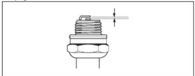
- Replace the spark plug if it is necessary.
To inspect the augers and the scraper bar
- Before each use, inspect the augers and the scraper bar for wear.
- If the edge of the scraper bar is worn, reverse the scraper bar. If the scraper bar has damages or is worn on both edges, replace it.
- If the edges of the augers are worn, contact an authorized service center to replace them.
To replace the auger shear pins
The auger shear pins protect the product from damage. The auger shear pins break if an object comes into the moving parts.

CAUTION: Use only original equipment shear pins supplied with the product.
- If an auger shear pin breaks, stop the engine and wait for the moving parts to stop.
- Remove the ON/OFF key and disconnect the spark plug cable.
- Align the hole in the auger hub (B) with the hole in the auger shaft (C) and install a new 1/4 - 20 × 2 shear pin (A).
- Install a 1/4 -20 locknut (D) on the shear pin and tighten.
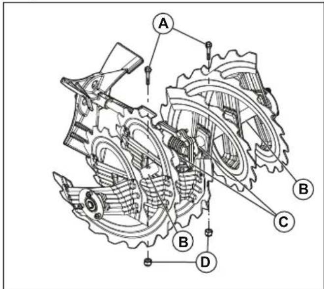
- Put the ON/OFF key in the ignition and connect the spark plug cable to the spark plug.
To replace the impeller shear pins
The impeller shear pins protect the product from damage. The impeller shear pins break if an object comes into the moving parts.

CAUTION: Use only original equipment shear pins supplied with the product.
- If an impeller shear pin breaks, stop the engine and wait for the moving parts to stop.
- Remove the ON/OFF key and disconnect the spark plug cable.
-
Align the hole in the impeller hub (A) with the holes in the impeller shaft (B) and install a new 1/4-20 shear pin (C).
-
Install a 1/4 -20 locknut (D) on the shear pin and tighten.
- Put the ON/OFF key in the ignition and connect the spark plug cable to the spark plug.
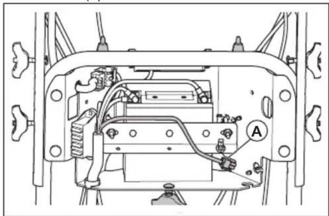
To replace the fuse
The fuse holders are installed behind the battery cover.
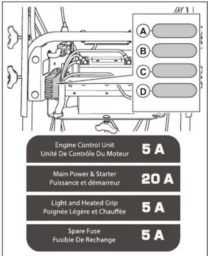
- Replace the fuse for engine control unit (A) with a 5 A fuse.
-
Replace the fuse for the starter solenoid (B) with a 20 A fuse.
-
Replace the fuse for the LED and the heated grip (C) with a 5 A fuse.
- Position (D) contains a backup 5 A fuse.
To examine the tires
- Keep the tires free of fuel, oil and chemicals to prevent damage to the rubber.
- Keep the tires away from stumps, stones, ruts, sharp objects and other objects which can cause damage to the tires.
- Keep the tire pressure correct, see Technical data on page 29.
To clear a clogged discharge chute deflector
Do not unclog the discharge chute deflector before the following operations are made.
- Release the auger engagement and the drive engagement at the same time.
- Wait 10 seconds to make sure that the augers have stopped.
- Stop the product.
- Use the tool for cleaning (at least 37~cm 15 in.) long, included in some models) to remove the clog.

WARNING: Do not put your hands into the discharge chute deflector or inside the auger bucket.
To replace the scraper bar
- Put the scraper bar (A) in a reversed position when it is worn to the edge of the housing.
- Replace the scraper bar if it is worn on both sides or if it is damaged.
Drive belts

WARNING: The v-belts on your product are of special construction and should be replaced by original equipment manufacturer (OEM) belts available from your nearest service center. To use other belts than OEM can cause personal injury or damage to the product.

WARNING: The belt replacement requires separation of the product. While separating the auger housing from the frame, it is important that an assistant stands in the operating position and holds the product handles. Serious personal injury and/or damage to the product could occur if the product falls during the belt replacement process.
To prepare for replacement of the belts
- Remove the fuel from the fuel tank.
- Loosen the lock nut (A) that secures the chute rotator head (B) to the mounting bracket (C) to remove the discharge chute.
- Loosen the two screws (A) that secure the belt cover (B) to the frame (C) and remove the belt cover.
To remove the drive belt
-
Remove the auger belt (A). See To remove the auger belt (for ST 424/427/430 only) on page 22.
-
Remove the 9/16 in. pulley bolt (B) and remove the engine pulley (C) from the engine.
- Remove the drive belt (D) from the lower pulley (E).
To install the drive belt
- Put the drive belt onto the lower pulley (E).
Note: Make sure that the drive belt is put in the lower pulley groove properly.
- Put the drive belt in the groove of the engine pulley (C).
- Install the 9/16 in. pulley bolt (B) and attach the engine pulley (C) on the engine. Tighten the pulley bolt (41-47 Nm/30-35 Ft. Lbs).
- Install the auger belt (A). See To install the auger belt on page 23.
- Operate all controls to make sure that the drive belt is installed correctly and that all components move correctly.
To install the belt cover
- Install the belt cover (B) on the frame (C) and tighten the two screws (A).
- Install the discharge chute.
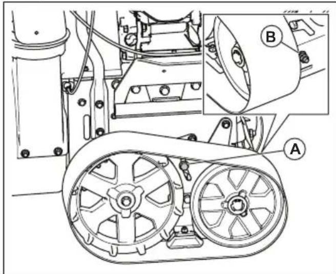
To adjust the drive belt tension
- Remove the belt cover. See To prepare for replacement of the belts on page 21.
- Loosen the idler pulley nut (A).
- Move the idler pulley (B) in the direction of the belt to increase the belt tension. Move it away from the belt to decrease the belt tension.
- Tighten the idler pulley nut (A).
- Press and then release the drive speed control lever. If the drive belt has tension when the drive speed control lever is released, move the idler pulley away from the drive belt to release the belt tension.
- Install the belt cover. See To install the belt cover on page 22.
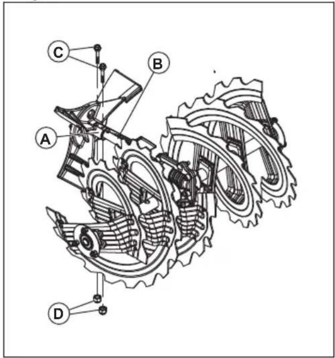
To remove the auger belt (for ST 424/427/430 only)
- Remove the 5/16" nut and the cable cover (E) from the frame.
- Remove the top 5/16" bolts and the lower 14 bolts (D) from the 2 sides of the frame. Do not discard the bolts.
- Loosen but do not remove the lower 5/16" bolts (C) on the 2 sides of the frame.
- Remove the auger belt (B) from the engine pulley (A).
- Tilt the rear section down. The front section tilts forward at the same time. The bottom bolt is a hinge between the front and rear sections.
- Put a wooden block below the hinge point to set the product in the tilted position.
- Move the auger brake arm and remove the auger belt (B) from around the auger brake arm.
To remove the auger belt (for ST 424T/427T/ 430T only)
- Remove the 5/16" nut and the cable cover (E) from the frame.
- Remove the top 5/16" bolts from the 2 sides of the frame. Do not discard the bolts.
- Remove the lower 5/16" bolts (C) on the 2 sides of the frame.
- Remove the auger belt (B) from the engine pulley (A).
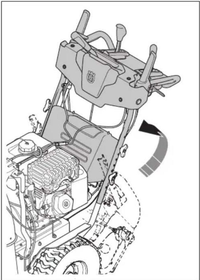
- Use the adjustment lever for the auger bucket to tilt the rear section down. The front section tilts forward at the same time. The bottom bolt is a hinge between the front and rear sections.
- Put a wooden block below the hinge point to set the product in the tilted position.
- Move the auger brake arm and remove the auger belt (B) from around the auger brake arm.
To install the auger belt
- Move the auger brake arm (G). Put the auger belt around and in the groove of the auger pulley (E).

CAUTION: Make sure that the belt is not caught between the frame and auger housing as you put the unit together.
- Remove the wooden block from below the product.
- Lift the handles to tilt the rear section up. The front section tilts back and pivots to attach to the rear section.
- Make sure that the belt is put in the auger pulley (E) groove correctly.
- Install the 5/16" bolts (C), and tighten (11-16 Nm).
- For ST 424/427/430 only: Install the 14 bolts (D) and tighten (5-8 Nm).
- Install the auger belt (B) on the engine pulley (A). Make sure that the belt is put correctly around the idler pulley and installed correctly in the engine pulley groove.
- Install the cable cover (F) and the 5/16" nut on the frame.
- Operate all controls to make sure that the auger belt is installed correctly and that all components are moving correctly.
To adjust the auger belt tension
Note: An assistant is necessary to do this task.
-
Remove the belt cover. See To prepare for replacement of the belts on page 21.
-
Loosen the idler pulley nut (A).
- Move the idler pulley (B) in the direction of the auger belt to increase the belt tension. Move it away from the auger belt to decrease the belt tension.
- Tighten the idler pulley nut (A).
- Have the assistant stay 3m (10 feet) in front of the product to monitor the movement of the auger.
- Push and then release the auger engagement to start and stop the auger.
- Measure the time for the auger to stop moving. If the auger stops after more than 5 seconds, release the belt tension.
- When the auger stops moving after less than 5 seconds, install the belt cover. See To install the belt cover on page 22.
To adjust the auger control cable
- Remove the cable cover on the right hand side of the frame (D).
- To remove slack from the auger control cable, unscrew the bottom jam nut (B) and tighten the top jam nut (B) until the auger belt tension has increased.
- Retest the auger engagement. Repeat adjustment as needed until only a small amount of slack remains in the cable when the lever is disengaged.
- Tighten the bottom jam nut to lock in the tension.
Note: You may also tension the auger belt by adjusting the idler pulley as a secondary option. If the adjustment does not resolve the problem, replace the auger belt. See To install the auger belt on page 23.
To adjust the release cable of the discharge chute
- To adjust the release cable, turn the cable adjuster until the release lever of the discharge chute does not move freely.
To adjust the left and right discharge chute cables
-
Put the discharge chute lever in the center position.
-
Turn the cable adjusters until the discharge chute points straight forward, and the cables are tight.
- Loosen the cable adjusters 14 turn to make the cables less tight.
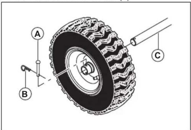
To remove the wheels
- Remove the wheel pin (A) and the retainer pin (B).
- Remove the wheel from the axle (C).
To adjust the tension of the continuous tracks (for ST 424T/427T/430T only)
Note: Tools that are necessary for this task: a 9/16" deep socket, a 9/16" wrench and a 5 kg (10 lbs) weight.
- Loosen the locking screw (A) 1 turn.
- Remove the rear locknut (B) to give access to the adjustment nut.
- Put a 5kg (10 lbs) weight (C) on top of the continuous track, in the center between the 2 wheels.
- Turn the adjustment nut (B) until the distance (D) between the continuous track and the steel plate is between 3.175 and 6.350mm (0.125 and 0.250 in). wide.
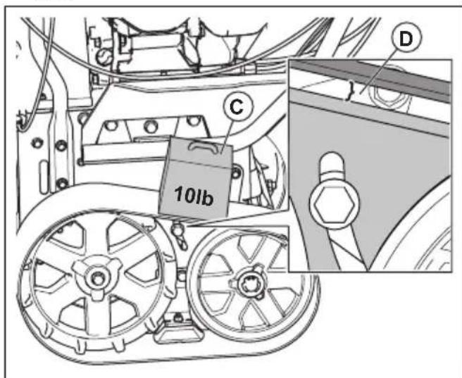
- Attach the locking screw (A) and then the rear locknut (B).
To clean the product
- Clean plastic parts with a clean and dry cloth.
- Do not use a high pressure washer to clean the product.
- Do not flush water directly on the motor.
Troubleshooting
| Problem Possible | cause Solution | |
| The product does not start | The safety ignition key is not inserted. Insert the safety ignition key. | |
| The product is out of fuel. Fill the fuel tank with fresh, clean gasoline. | ||
| The ON/OFF key is OFF. Move the ON/OFF key to ON position. | ||
| The engine is not primed. Prime the engine. | ||
| The engine is flooded. Wait a few minutes before | restarting, DO NOT prime. Restart the engine while full throttle and the choke in OFF (CLOSE) position. | |
| The spark plug cable is not connected. Connect the cable to the spark plug. | ||
| The spark plug is bad. Replace the spark plug. | ||
| There is water in the fuel or the fuel is too old. Empty the fuel tank and carburetor. Fill the fuel tank with fresh, clean gasoline. | ||
| There is vapor locked in the fuel line. Make sure that all the fuel line is below the outlet of the fuel tank. The fuel line should run continuously down from fuel tank to carburetor. | ||
| Other causes. Inspect the starting procedures carefully in this manual. | ||
| The fuel switch (if equipped) is in CLOSE (OFF) position. | Turn the fuel switch to OPEN (ON) position. | |
| The throttle is in STOP position. Move the throttle to FAST position. | ||
| The starting battery is not charged. Charge the starting battery. | ||
| The starting battery needs to be replaced. Replace the starting battery. | ||
| The engine control unit does not receive power. Inspect the ECU fuse and wiring. | ||
| The starter solenoid does not engage. Inspect the starter fuse and wiring. | ||
| The fuel injector does not trigger. (For ST 424T/427T/430T only) | Contact an authorized service center. | |
| The fuel pump does not receive power. (For ST 424T/427T/430T only) | Contact an authorized service center. | |
| Decreased power The spark | plug cable is not connected. Connect the cable to the spark plug. | |
| The product throws too much snow. Decrease the speed and the width of the swath. | ||
| The fuel tank cap is covered with ice or snow. Remove the ice and the snow on and around the fuel tank cap. | ||
| The muffler is dirty or clogged. Clean or replace the muffler. | ||
| Improper cable length. Adjust the cable. | ||
| The muffler is blocked. Make sure that the engine is cool. Clear the blockage. | ||
| The air intake of the carburetor is blocked. Make sure that the engine is cool. Clear the blockage. | ||
| The fuel injector does not trigger. Contact an authorized service center. | ||
| The engine idles or runs roughly | The fuel line is blocked. Clean the fuel line. | |
| There is water in the fuel or the fuel is too old. Empty the fuel tank and carburetor. Fill the fuel tank with fresh, clean gasoline. | ||
| The carburetor needs to be replaced. Contact an authorized service center. | ||
| The fuel injector does not trigger. Contact an authorized service center. | ||
| Excessive vibration / Handle movement | Some parts are loose. The augers are damaged. | Tighten all fasteners. Replace the damaged parts. If vibration remains, contact an authorized service center. |
| The handles are not positioned correctly. Make sure that the handles are locked into position. | ||
| The adjustment lever nuts are loose. Tighten the nuts until the handle feels safe. | ||
| The starter rope handle is hard to pull | The starter rope handle is frozen. | Slowly pull out as much rope out of the starter as possible and release the starter rope handle. If the engine does not start, repeat the procedure or use the electrical starter. |
| The starter rope is interfering with components. | The starter rope should not touch any cables or hoses. | |
| Loss of traction drive/slowing of drive speed | The belt slips. Adjust the cable. Adjust the belt. | |
| Loss of snow discharge or slowing of snow discharge | The belt is worn. Check / replace the belt. Adjust the pulley. | |
| The belt is off the pulley. Check / reinstall the belt. Adjust the pulley. | ||
| The chute deflector is clogged. Clean the chute deflector. | ||
| Foreign objects clog the augers. Remove the debris or the foreign object from the augers. | ||
| The shear pin is broken. Replace the broken shear pin. | ||
| Excessive snow and ice build up in between continuous track components. Remove snow and ice build up from in between continuous track components. | ||
| The lights are not on (if so equipped) | The engine is not running. Start the engine. | |
| The cable connection is loose. Do a check of the cable connections at the engine and the lights. | ||
| The LED is burnt out. Replace the LED light module. Indi-vidual LEDs can not be replaced. | ||
| The fuse is blown. Replace the fuse. Make sure that there is no short circuit. | ||
| The chute rotator is difficult to move | There is debris in the chute rotator mechanism. Clean the internal parts of the chute rotator mechanism. | |
| The cables are kinked or damaged. Make sure that the cables are not kinked. Replace the cables that are damaged. | ||
| The release cable needs adjustment. Adjust the release cable. | ||
| The product turns to one side | The tire pressure is not equal. Adjust the tire pressure and fill the tire. | |
| The product drives with only one wheel. Inspect the tire lock pin. | ||
| Uneven sled adjustment. Adjust the skid plates and the sledge. | ||
| Uneven skid plates adjustment. Adjust the skid plates and the sledge. |
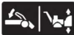
Transportation, storage and disposal
Transportation and storage
- For storage and transportation of the product and fuel, make sure that there are no leaks or fumes. Sparks or open flames, for example from electrical devices or boilers, can start a fire.
Always use approved containers for storage and transportation of fuel. -
Empty the fuel tank before you put the product in storage for a long period of time. Discard the fuel at an applicable disposal location
-
Safely attach the product during transportation to prevent damage and accidents.
- Keep the product in a locked area to prevent access for children or persons that are not approved.
- Keep the product in a dry and frost free area.
- Charge the battery during long-term storage.
Examine and clean the battery terminals before long-term storage.
Disposal
- Obey the local recycling requirements and applicable regulations.
-
Discard all chemicals, such as engine oil or antifreeze, at a service center or at an applicable disposal location.
-
When the product is no longer in use, send it to a Husqvarna dealer or discard it at a recycling location.
- Discard the battery at a service center or discard it at a disposal location for used batteries.
Technical data
| Technical data | ||||||
| ST 424 ST 427 ST 430 ST 424T ST 427T $T 430T | ||||||
| Dimensions | ||||||
| Weight, with empty tanks, kg | 140 145 150 | 160 165 170 | ||||
| Max. operating tire pressure, PSI | 18 18 20 | N/A N/A N/A | ||||
| Engine | ||||||
| Brand Husqvarna Husqvarna | Husqvarna H | husqvarna Husqvarna Husqvarna | husqvarna Husqvarna | |||
| Displacement, cc 291 369 4 | 14 306 369 420 | |||||
| Fuel type Unleaded regular (maximum 10% ethanol) | ||||||
| Fuel capacity, gal / l 0.62 / 2 | 35 0.62 / 2.35 | 0.62 / 2.35 0.95 / 3.60 0.95 / 3.60 0.95 / 3.60 | 3.60 0.95 / 3.60 | |||
| Oil type (API SJ-SN) SAE 5W30 (below 0°C (32°F)) | ||||||
| Oil capacity fl. oz. / l 32 / 0.95 | 38 / 1.12 38 / | 1.12 32 / 0.95 | 38 / 1.12 38 / | 1.12 | ||
| Electrical system | ||||||
| Spark plug F6RTC | ||||||
| Spark plug electrode gap (in. / mm) | 0.027 / 0.686 | |||||
| Noise emissions4 | ||||||
| Sound power level, measured dB(A) | <105 db <105 | db <105 db <105 | db <105 db <105 | db <105 db | ||
| Sound power level, guaranteed LWA dB(A) | 105 db 105 db | 105 db 105 db | 105 db 105 db | |||
| Vibration levels, ahveq5 | ||||||
| Vibration level on the handle, m/s2 | 4.57 m/s2 | 5.07 m/s2 | 5.83 m/s2 | 4.11 m/s2 | 4.65 m/s2 | 5.25 m/s2 |
EC Declaration of Conformity
CONTENTS OF THE EC DECLARATION OF CONFORMITY
We, Husqvarna, SE-561 82 Huskvarna,SWEDEN, declare under our sole responsibility that the represented product:
| Description Snowthrower | |
| Brand Husqvarna | |
| Platform / Type / Model ST 424, ST 427, ST 430, ST 424T, ST 427T, ST 430T | |
| Batch Serial number dating 2018 and onwards | |
complies fully with the following EU directives and regulations:
| Directive/Regulation Description | |
| 2006/42/EC "relating to machinery" | |
| 2014/30/EU "relating to electromagnetic compatibility" | |
| 2000/14/EC; 2005/88/EC "relating to outdoor noise" |
Harmonized standards and/or technical specifications applied are as follows: EN ISO 12100, ISO 14982, ISO 8437, ISO 3744, EN 1032
In accordance with directive 2000/14/EC, Annex V, the declared sound values are stated in the technical data section of this manual and in the signed EC Declaration of Conformity.
The supplied snowthrower conforms to the example that underwent examination.
Inhalt
Einleitung. 31
Fehlerbehebung. 59
Sicherheit. 34
Commanded acceleration
(ST 424/427/430) Supporto cavo (1)

Rondella in nylon (1)

Original instructions
Originalanweisungen