HSIP6000 - Surveillance Camera SWITEL - Free user manual and instructions
Find the device manual for free HSIP6000 SWITEL in PDF.
| Product type | Surveillance camera with monitor |
| Brand | Switel |
| Model | HSIP6000 |
| Monitor screen size | 7 inches (17.8 cm) |
| Screen resolution | 800 x 480 pixels |
| Camera resolution | 1280 x 720 (720p) |
| Viewing angle | 68° (diagonal) |
| Night vision | Yes, IR LEDs, range up to 10 meters |
| White LED lighting | 6W, manual control, timer or motion detection |
| Wireless range | Up to 300 meters in line of sight |
| Operating frequency | 2.4 GHz (2.400 - 2.4835 GHz) |
| Monitor power supply | 5V DC 2A (AC adapter included) |
| Camera power supply | 9V DC 2A (AC adapter included) |
| Monitor battery | Lithium 3.7V 2000 mAh rechargeable |
| Storage | SDHC card up to 128 GB (in monitor) |
| Protection rating | IP65 (camera) |
| Audio | Built-in microphone and speaker, two-way communication |
| Motion detection | Yes, adjustable sensitivity and zones |
| Mobile app | MyCam View (iOS and Android) |
| Max number of cameras | 4 |
| Main functions | Live surveillance, scheduled recording, alarm, scan, auto-sequence, talk-back |
| Maintenance | Clean the housing with a soft, dry cloth, do not use solvents |
| Safety | Use only the supplied adapters, do not open the device, follow disposal instructions |
Frequently Asked Questions - HSIP6000 SWITEL
User questions about HSIP6000 SWITEL
0 question about this device. Answer the ones you know or ask your own.
Ask a new question about this device
Download the instructions for your Surveillance Camera in PDF format for free! Find your manual HSIP6000 - SWITEL and take your electronic device back in hand. On this page are published all the documents necessary for the use of your device. HSIP6000 by SWITEL.
USER MANUAL HSIP6000 SWITEL
HSIP 6000 Home Monitoring
HD Digital Surveillance Monitor
Bedienungsanleitung
User's Manual
natural_image
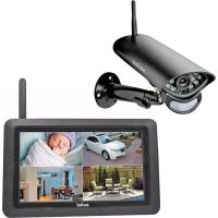
Black-and-white photo of a surveillance camera with LED lights and a tablet displaying four scenes: a car, sleeping baby, dining area, and home (no visible text or symbols)DEUTSCH
ENGLISH
FRANÇAIS
ITALIANO
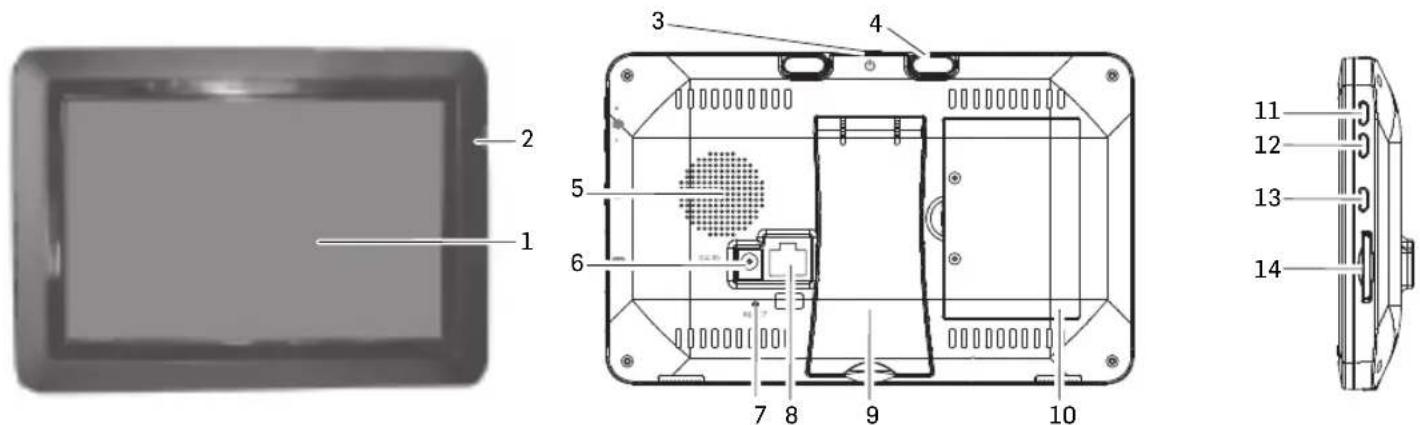
Monitor (Empfänger)
text_image
Labeled diagram of a security camera with numbered parts and a separate view showing its top and side views.text_image
Camera 1 Camera 2 Camera 3 Camera 4Telgo AG, Route d'Agy 16, 1763 Granges-Paccot, Switzerland
Pflegehinweise
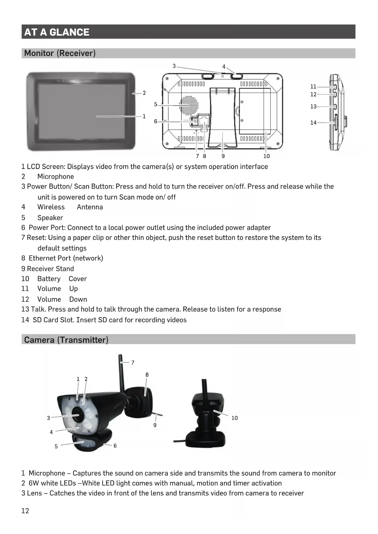
1 LCD Screen: Displays video from the camera(s) or system operation interface
2 Microphone
3 Power Button/ Scan Button: Press and hold to turn the receiver on/off. Press and release while the unit is powered on to turn Scan mode on/ off
4 Wireless Antenna
5 Speaker
6 Power Port: Connect to a local power outlet using the included power adapter
7 Reset: Using a paper clip or other thin object, push the reset button to restore the system to its default settings
8 Ethernet Port (network)
9 Receiver Stand
10 Battery Cover
11 Volume Up
12 Volume Down
13 Talk. Press and hold to talk through the camera. Release to listen for a response
14 SD Card Slot. Insert SD card for recording videos
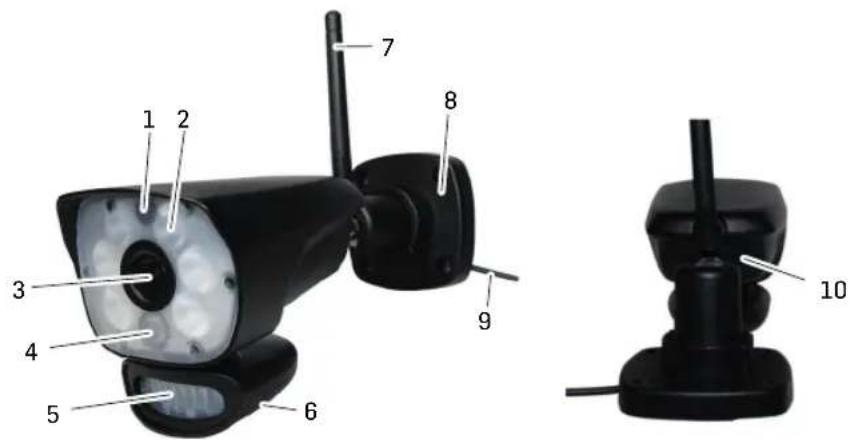
Camera (Transmitter)
text_image
Technical diagram of a security camera with numbered parts labeled for identification.1 Microphone – Captures the sound on camera side and transmits the sound from camera to monitor
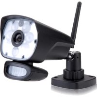
2 6W white LEDs – White LED light comes with manual, motion and timer activation
3 Lens – Catches the video in front of the lens and transmits video from camera to receiver
4 IR LED – Infrared LEDs provide viewing in no/low light conditions
5 PIR sensor – Detects motion in front of the lens and emits detection signal to transmitter
6 Speaker – Produces the sound transmitted from the monitor
7 Camera Antenna – Receives & Sends signals to or from the Receiver
8 Bracket – Use the bracket to mount the camera on a wall or other flat surfaces
9 AC Adaptor Jack – Plug the AC adaptor to the jack for camera's power supply
10 Pairing Button – The pairing button is located on the back of the camera behind by the stand mount
Note: This camera includes an Auto Mechanical IR Cut Filter. When the camera changes between day mode and night vision mode, an audible clicking noise may be heard coming from the camera. This clicking is normal, and indicates that the camera filter is working.
SET UP THE HARDWARE
Monitor
1 Flip out the stand on the back of the monitor; and position the antenna.
2 Connect an AC adaptor to the power input on the side of the monitor. Connect the other end of the adapter to a standard indoor power outlet.
3 Press and hold the POWER button on the top of the monitor for 3 – 4 seconds to power it up.
4 The monitor displays the start up UI for a few seconds and then transitions to the LIVE view. The screen remains dark until the cameras are powered up.
Camera
General
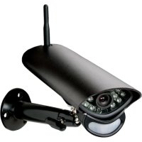
The camera included with your monitor is weatherproof and have an IP65 rating. Water can be sprayed on them and they will still work; however, the cameras cannot be submerged.
Although the cameras can be exposed directly to the rain, it is recommended that, if they are used outdoors, they be mounted under some type of cover like a patio overhang or eave. As rainwater drops start to dry on the camera glass, it can create spots that will reflect the light from the infrared LEDs used for night vision, thus causing lower quality video.
Also, as dust, grime, and cobwebs accumulate on the camera glass, they can reflect light from the infrared LED and might lower video quality. Periodically clean the lens glass with a soft cloth.
Placement Considerations
Consider the following when placing cameras:
- The clearest line-of-sight between the camera and monitor is best.
- Walls, especially brick and concrete, shorten the transmission distance.
- Placement next to windows allows better transmission.
- Optimized motion detection range is 6...18 feet for the camera. The farther away an object is, the less accurate the motion detection.
- Avoid having a direct light source in the view of the camera, including street lights, ceiling or floor lamps, spotlights in the driveway, etc.
- Rainfall, pool water ripples/reflections, tree/shrub leaves blowing in the wind – and the shadows they create – can generate motion detection false alarms.
INSTALL CAMERAS
When you are positioning the camera, bring the monitor along; it's much easier to get the camera into the right position when you have the display handy.
1 Position the camera where you want it, plug it into power, and check video on the monitor. Move the camera if the view is not what you want.
2 Hold the base of the camera stand where you want to mount it and mark the location of the screw holes.
3 Use the included screws and anchors to attach the base to the wall or ceiling.
4 Tug gently on the stand to make sure it is securely in place.
MONITOR SCREEN
The monitor's screen has 3 main parts:
• Live View area. The main screen area displays live video from the camera(s).
- Pop Out Menu Tab. Tap this tab to display 4 menus that let you manage the system.
- Icon bars. Icons display on the top and bottom of the monitor screen.
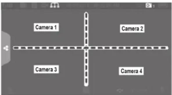
Viewing Modes
The Live View area displays live video from the cameras. Each camera can display in its own section of the screen (quadrant) or on the full screen.
text_image
Camera 1 Camera 2 Camera 3 Camera 4There are 4 viewing modes:
- Quad mode splits the screen's image area into 4 quadrants and displays active camera video in each quadrant. Tap the center of the quadrant to enter Single Channel mode.
- Single Channel mode displays one camera at a time on full screen. Press to change between the channels. Tap the center of the image to return to Quad mode.
- With Scan mode, the monitor's screen and speakers are off until a camera detects motion. That camera then displays at full screen (sound and video on) until there has been no motion for 15 seconds. After that, the monitor screen turns off again. Press and release POWER to turn Scan mode on.
- Auto Sequence. Displays each channel automatically in sequence in full screen display. The system defaults to Auto Sequence mode when Scan mode is turned off. Tap SEQ to turn Auto Sequence mode off and return to Quad mode.
SYSTEM OPERATION
Your monitor operates through a series of screens that let you choose groups of operations.
GB
LIVE VIEW SCREEN
The Live View screen is the monitor's main screen that displays video from your camera(s). You can have the system display a single camera or you can set the screen to display all of them. You can also set the screen to cycle between all live video feeds. Tap the icon to change the Live screen video displays.
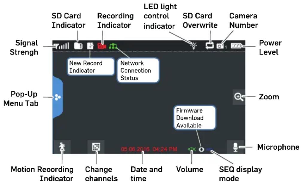
LIVE SCREEN ICONS
Different icons display on the monitor screen depending on what is going on with your cameras. This image shows an example of what could be on your screen (the video image is removed to make it easier to see the icons). A table follows of possible icons and their definitions.
Live Screen Example
text_image
SD Card Indicator Recording Indicator LED light control indicator SD Card Overwrite Camera Number Signal Strength Power Level New Record Indicator Network Connection Status Pop-Up Menu Tab Zoom Firmware Download Available 05 06 2016 04:24 PM Microphone Motion Recording Indicator Change channels Date and time Volume SEQ display modeTull SIGNAL INDICATOR: Shows how strong the camera's signal is. Signal ranges from 4 bars down to 0 bars (out of range).

SD CARD: This graphic displays if an SD card is inserted into the monitor. If blue, recording space is available. If red, the SD card is full. Tap this icon to view recorded files.
NEW RECORD INDICATOR: New recordings are saved on the SD card.

RECORDING INDICATOR: When this icon flashes red, it indicates that recording is in progress. NETWORK STATUS INDICATOR:

Green- System is connected to the internet and the monitor is connected with internet mode. Yellow- System is connected to internet and the monitor is connected with intranet mode. Red- Connection has failed or system is not connected to a network.

LED LIGHT CONTROL INDICATOR: Touch this icon to control the LED light on/off SD CARD OVERWRITE: Displays if the SD card is allowed to overwrite files when it is full.

CHANNEL INDICATOR: Displays the current channel number you are currently viewing. If viewing multiple cameras at once, the camera indicator will appear above each video display.
BATTERY INDICATOR: Indicates the LCD monitor's battery life:
Flashing Red- Low battery
Green- Full battery
Flashing Green-Charging

ZOOM INDICATOR: When you tap this icon on the screen, the monitor breaks the screen image into 5 areas. Tap the area you want to see in Zoom. That area displays in 2X size. Tap the icon again to exit Zoom mode.
VOLUME INDICATOR: Indicates current audio volume. You must be in sigle channel viewing mode to change volume. Tap + or - to raise or lower the volume. displays when the volume is off (mute).

TALK BACK INDICATOR: Displays when TALK is pressed. Press and hold TALK on the side of the monitor to talk back through the camera. Release TALK to wait for a reply.

NEW DOWNLOAD: Displays if new firmware is available.
SEQ SEQUENCE INDICATOR: Displays when the monitor is in auto switch mode; it will change channels automatically.

CHANGE CHANNEL: Tap this icon to manually change channels.

MOTION RECORDING INDICATOR: Indicates motion detection status.
Blue - Automatic recording OFF.
Red - Automatic recording ON.
POP-UP MENU TAB: Tap to access the pop up menu system.
FUNCTIONS
Tap and the pop-up menus display.
Light settings
Turn on the LED light manually, create a schedule for automatic power on / off, and adjust the brightness of the LED light.
1

2 You have the following options:
- Tap the number corresponding to the camera to manually turn the light on or off.
- Tap "Duration" and set how long the light should be switched on after the movement has been triggered. You can turn off the light or set it to 1/3/10 min.
- Tap "Timer" and specify a schedule for which the light should be switched on.
- Touch "Dimmer" and adjust the brightness of the LED lamp.
ALARM
When motion triggers the camera to begin recording, the monitor sounds an alarm tone. This screen lets you determine how loud that tone will be.
1

2 Tap + or – to increase or decrease the alarm volume. Tap when you are finished.
BRIGHTNESS
This feature allows you to set each camera's brightness level.
1

2 Tap + or – to increase or decrease the monitor screen brightness. Tap when you are finished.
GENERAL SETTINGS
The General Settings screen contains 6 subsections, each of which may contain sub-screens. These sub-GB screens let you set features about your system. You can turn cameras on and off, establish a specific schedule for specific cameras to record, set the date and time, and motion detection sensitivity, among other features.
1

| Main Screen Sub-Screen | What it Does | |
| Camera Setup | Pairing | This system comes with cameras already paired. Use Pairing to assign these cameras to different channels or to pair additional new cameras to the monitor. |
| ON/OFF | Makes the cameras visible to the monitor. | |
| Resolution | Adjusts the video quality of each camera. | |
| Recording Setup Duration | Set the length of time | the camera records once motion sensitivity triggers the camera to record.Choices are 15 seconds, 30 seconds, or 1 minute (Default - 15 seconds) |
| Schedule Recording Set up | a schedule for pre-determined recording times and lengths. | |
| File Overwrite Overwrites | the oldest recorded data on the SD card once the card is full. | |
| System Settings Date | & Time Set the current time. | |
| Time Zone · Set the time | zone for your system.· Enable/Disable Daylight Savings Time. | |
| Language Changes language setting for the monitor. | ||
| Default Settings Restores | the system to default settings. | |
| Format SD Card Reformats | the SD card and deletes all existing data. | |
| Information Displays firmware information for the monitor and each camera. | ||
| Motion Detection Settings | A single screen lets you set motion detection sensitivity for each camera.It also lets you determine which viewing areas for each camera should be masked from motion detection. | |
| Main Screen Sub-Screen | en What it Does | |
| Network Setup Advanced | Setup | Set up Dynamic or Static IP address. |
| ResetPassword | Reset app password to the default (000000). | |
| Information Displays and | allows you to change informationabout your network and the monitor's unique UIDnumber. | |
| Firmware Upgrade Let | s you select how you want to upgrade your firmware (from SD cardor from server). | |
ADDING NEW CAMERAS
Your monitor supports a total of four active cameras at a time. When you add a camera, you have to pair it to the monitor (that is, you have to “introduce” the camera and monitor to each other so they can communicate).
- If a camera is already assigned to the channel you want to assign the new camera to, the monitor overwrites the existing camera link with the new one.
- Only pair one camera at a time! The monitor links to the first camera it detects. If two or more camera are in pairing mode, you can't control which camera the monitor will detect first.
PAIR CAMERAS
1 From the Pairing Camera screen, tap the camera image you want to pair. A processing icon displays for a 30 second countdown.
2 During the 30 second countdown, quickly press and release the Pairing button on the camera.
3 The system automatically adjusts the Live View screen accordingly.
TROUBLESHOOTING CAMERA PAIRING
| If... | Try... |
| the camera's signal status icon shows no bars | ·making sure the camera is plugged in.·making sure that the camera's antenna is attained and the monitor's antenna is extended.·making sure the camera is paired to the correct channel.·re-pairing the camera and monitor. |
| the camera won't pair with the monitor | ·making sure the camera is plugged in.·pressing and releasing the pairing button quickly. Do not press and hold the pairing button. |
MONITOR BASIC OPERATION (QUICK GUIDE)
| Manually start/stop recording video | 1 Tap the blue icon on the monitor screen. The icon turns red and flashes, indicating that recording have started.2 Tap the icon again to stop recording. The icon turns blue. |
| Set up automatic recording schedule | 1 From General Settings/Recording Setup, tap icon. The Schedule Recording Overview screen displays.2 Tap MODIFY to view the Recording Setup screen. |
| Delete recording schedule | 1 From General Settings/Recording Setup, tap icon. The Schedule Recording Overview screen displays.2 Select the day you want to modify and tap MODIFY to view the recording schedule for that day.3 Select the camera(s) whose schedule you want to delete. Enter the schedule (or part of a schedule) you want to delete and tap DELETE. |
| Watch recorded video | 1 Tap the SD card icon on the monitor. The Recording File List displays the recorded files.2 Tap the day you want to view, and then tap the file.3 The video begins playing. |
| Delete recorded videos | 1 From the Recorded File List, tap .2 Tap YES to confirm deletion. |
| Two-way talk | From the Live View screen, press and hold the TALK button at the side of monitor, sound is now audible through the camera.Release TALK button, the Two-way talk mode exits. |
| Change channels (view a different camera) | 1 Tap the icon.2 The next channel displays. |
1 Download MyCam View from AppStore or Google Play to your smartphone or tablet.
2 Connect the monitor to your router using an Ethernet cable so that it has an Internet connection (the icon lights green).
The following example shows how to use the Android app. If you use a device with iOS, there may be slight deviations depending on the system. However, it should not be difficult to use the features on your iOS device to the same extent.
Add camera
1 Start MyCam View and tap on the icon or on the respective text.
2 There are two ways to add the camera:
- Enter the UID number (below the QR code on the back of the monitor) in the UID input field.
- Tap Scan and scan the QR code on the back of the monitor.
3 In the Name line, you can enter any name for the camera.
4 Enter the password for the camera in the line Password (in delivery state 000000).
5 Tap OK.
6 You see a list of the devices with their UID numbers and the online status.
7 Tap the desired camera to view its live image.
Operating the APP
While the live image is displayed, you can use the icons at the bottom of the display to access the following functions:
- Access to the snapshots / photos (which you have triggered with the app).
- Take a snapshot.
- Turning the sound from the camera on / off.
- Turn on the loudspeaker on the camera (Talk-back function).
- Turn the LED light on the camera on / off.
If you have access to several cameras with the APP, you can use the icons, etc ^2 at the top of the display to select the desired camera for displaying the live image.
Settings in the APP
Whilst in the list display of the connected cameras (which can be reached with the back button of your mobile phone during the live image display), you can make the following settings:

- Reconnect to the camera if the connection is broken.

- Edit device settings.
The UID of the camera is shown and you can change the name of the camera.
Advanced settings:
- Password Setting: Change the password for camera access
- Adjust the video quality
- Light settings (corresponding to the light settings via the monitor)
- Alert settings
- Device informationen

- Displays the list of recorded events.
By tapping certain time periods can be queried.

- Displays the list of captured snapshots.

- Delete device: The camera is removed from the APP.
APPENDIX
Safety Information
- Please read this operating instruction manual thoroughly and keep it for further use.
- Prevent excessive exposure to smoke, dust, vibration, chemicals, moisture, heat and direct sunlight.
- Furniture polish, over time, may disintegrate the rubber feet of the device which may stain your furniture. To avoid a potential stain, you may want to place the device on a pad or mat.
- Only use the power adapter plugs contained in the material supplied since other power adapter plugs could damage the devices.
- Ensure access to the power adapter plugs is not obstructed by furniture or such.
Intended use
The camera serves a video stream to the monitor. Any other use is considered unintended use.
Unauthorised modification or reconstruction is not permitted. Under no circumstances open the devices or complete any repair work yourself. Observe all local directives and regulations.
Power adapter plug
Attention: Only use the power adapter plug contained in the material supplied since other power adapter plugs could damage the devices. Ensure access to the power adapter plug is not obstructed by furniture or such.
Pay attention that the plug and cable are in perfect condition. Kinked or worn cable represents the risk of a fatal accident!
The power adapter plug supplied fulfils the ecodesign requirements of the European Union (Directive 2009/125/EC). This means that, both in an operating state and in an idling state, the power consumption is considerably lower compared to power adapter plugs with an older design.
Disposal
In order to dispose of your device, take it to a collection point provided by your local public waste authorities (e.g. recycling centre). According to laws on the disposal of electronic and electrical devices, owners are obliged to dispose of old electronic and electrical devices in a separate waste container. The adjacent symbol indicates that the device must not be disposed of in normal domestic waste!
Batteries represent a hazard to health and the environment!
Never open, damage or swallow batteries or allow them to pollute the environment. They may contain toxic, ecologically hazardous heavy metals. You are legally obliged to dispose of power packs and batteries at the point of sale or in the corresponding containers provided at collection points provided by local public waste authorities. Disposal is free of charge. The adjacent symbols indicate that the batteries must not be disposed of in normal domestic waste and must be brought to collection points provided by local public waste authorities.

Packaging materials must be disposed of according to local regulations.
Declaration of conformity
This device fulfils the requirements stipulated in the EU directive:
2014/53/EU.

Conformity with the above mentioned directive is confirmed by the CE symbol on the device.
To view the complete Declaration of Conformity, please refer to the free download available on our website www.switel.com.
Telgo AG, Route d'Agy 16, 1763 Granges-Paccot, Switzerland
Maintenance
- Clean the housing surfaces with a soft, fluff-free cloth.
- Never use cleaning agents or solvents.
Technical data (monitor)
Frequency 2,400 ... 2,483.5 GHz
Data Rate 4 Mbps
Receiving Sensitivity -81dBm
Modulation Type GFSK with FHSS
Monitor display 7" (17,8 cm) Color LCD (800 x 480 pxl)
View Angle H: 140° V: 110°
SDHC-Memory card Max 128G
Lithium rechargeable battery 3.7V 2000mAh
Power Requirement 5 V DC 2 A +/- 5%
Operating Temperature (Monitor) -10°C ... +40°C / Humidity 0% ... 85%
Technical data (camera)
Frequency 2,400 ... 2,483.5 GHz
Data Rate 4 Mbps
Transmitting Power 16dBm (TYP)
Modulation Type GFSK with FHSS
Transmitting Distance up to 300m (Line of Sight)
Image Sensor Type 1/4" Color CMOS Image Sensor
Effective Pixels H: 1280 V: 720
Recording format ASF
Image Resolution / Frame Rate Cam x 1 : 720px1 @ 15 fps
Cam x 2 : VGAx2 @ 30 fps
Cam x 4 : VGA x 4 @ 10 fps
Lens 3.6mm / F1.9 (ICR cut Filter)
Viewing Angle (Diagonal) 68° (FOV)
IR LED / Night Vision Range 1PCS IR LED+6PCS white led /10m Night Vision Range
Power Requirement 9.0 VDC 2A +/- 5%
Power Consumption 1680mA Max (with IR ON and white led on and talk back)
500mA Max With talk back
Weather proof IP65
Operating Temperature
-10°C ... +50°C / Humidity 0% ... 85%
Guarantee
SWITEL equipment is produced and tested according to the latest production methods. The implementation of carefully chosen materials and highly developed technologies ensure trouble free functioning and a long service life.
The terms of the guarantee do not apply to the rechargeable batteries or power packs used in the products. The period of guarantee is 24 months from the date of purchase.
All deficiencies resulting from material of production faults which occur during the period of guarantee will be eliminated free of charge. Rights to claims under the terms of guarantee are annulled following intervention by the purchaser or third parties. Damage caused as a result of improper handling or operation, incorrect positioning or storing, improper connection or installation, Acts of God or other external influence are not covered by the terms of guarantee.
In the case of complaints, we reserve the right to repair or replace defect parts or provide a replacement device. Replacement parts or devices become our property.
Rights to compensation in the case of damage are excluded where there is no evidence or intent or gross negligence by the manufacturer.
If your equipment shows signs of defect during the period of guarantee, please return to the sales outlet in which you purchased the SWITEL equipment together with the purchase receipt. All rights to claims under the terms of guarantee in accordance with this agreement must be asserted exclusively with regard to your sales outlet.
Two years after the purchase of our products, claims under the terms of guarantee can no longer be asserted.
text_image
Technical diagram of a security camera with numbered parts labeled for identification.text_image
Camera 1 Camera 2 Camera 3 Camera 4Telgo AG, Route d'Agy 16, 1763 Granges-Paccot, Switzerland
text_image
Technical diagram of a security camera with numbered parts labeled for identification.text_image
Camera 1 Camera 2 Camera 3 Camera 4Telgo AG, Route d'Agy 16, 1763 Granges-Paccot, Switzerland

Sensore telecamera 1/4" Color CMOS image sensor
In the case of technical questions, please use the service form on our website: http://www.switel.com/en/product-information-technical-support/