
3708FC - Grass trimmer MAKITA - Free user manual and instructions
Find the device manual for free 3708FC MAKITA in PDF.

| Product type | Electric trim router |
| Brand | Makita |
| Model | 3708FC |
| Collet capacity | 6 mm or 1/4" |
| No-load speed | 26,000 min⁻¹ |
| Overall length | 308 mm |
| Net weight | 1.3 kg |
| Power supply | Single-phase mains, double insulation (without earth connection) |
| Electronic functions | Constant speed control, soft start |
| Lighting | Integrated LED lamp (model 3708FC) |
| Bit protrusion adjustment | By lever and knurled knob, tool-less |
| Base angle adjustment | From 0° to 45° (5° increments) |
| Sound pressure level | 76 dB(A) (uncertainty K=3 dB(A)) |
| Vibration emission | ≤ 2.5 m/s² (uncertainty K=1.5 m/s²) |
| Applications | Trimming and profiling of wood, plastic and similar materials |
| Maintenance | Periodic carbon brush replacement |
| Safety | Double insulation, automatic shutdown in case of overload, protection against accidental start |
| Included accessories | Copy guide, horizontal trim base, wrenches |
| Warranty | Consult an authorized Makita service center |
Frequently Asked Questions - 3708FC MAKITA
User questions about 3708FC MAKITA
0 question about this device. Answer the ones you know or ask your own.
Ask a new question about this device
Download the instructions for your Grass trimmer in PDF format for free! Find your manual 3708FC - MAKITA and take your electronic device back in hand. On this page are published all the documents necessary for the use of your device. 3708FC by MAKITA.
USER MANUAL 3708FC MAKITA
natural_image
Technical line drawing of a mechanical device with no visible text or symbols

1
002001 002002 2
3
001982 0020034
5
002004
002005
6
7
001984
8
natural_image
Line drawing of a hand using a power tool to cut or mark a circular component (no text or symbols)001985 001986
10 11
002006 002007
12 13
natural_image
Line drawing of hands using a tool to lift or adjust a wooden beam (no text or symbols)001989001988
14 15
001990
002008
16 17
002009
001993
18 19
001994
002010
natural_image
Line drawing of a hand holding a cable with attached mechanical components (no text or symbols)20 21
002011
002012
22 23
natural_image
Pure mechanical diagram showing a spring-loaded component with no text or symbols001145
24
001999
ENGLISH (Original instructions)
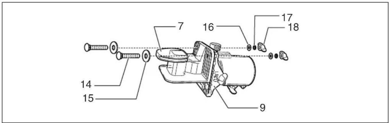
| Explanation of general view | ||
| 1 L e v e r | 15 Flat washer (large) | 29 Templet |
| 2 S c a l e | 16 Flat washer (small) | 30 Distance (X) |
| 3 Bit protrusion | 17 Spring washer | 31 Templet guide 10 |
| 4 Adjusting roller | 18 Wing nut | 32 Guide plate |
| 5 Wing bolt | 19 Workpiece | 33 Clamp screw (A) |
| 6 Graduation | 20 Bit revolving direction | 34 Center hole |
| 7 Trimmer shoe | 21 View from the top of the tool | 35 Nail |
| 8 Amount of chamfering | 22 Feed direction | 36 Adjusting screw |
| 9 B a s e | 23 Straight guide | 37 Clamp screw (B) |
| 10 Switch lever | 24 Screws | 38 Trimmer guide |
| 11 Loosen | 25 Screwdriver | 39 Bit |
| 12 Tighten | 26 Templet guide | 40 Guide roller |
| 13 Hold | 27 Convex portions | 41 Limit mark |
| 14 Bolt | 28 Straight bit | 42 Brush holder cap |
SPECIFICATIONS
Model 3708/3708F 3708FC
| Collet chuck capacity | 6 mm or 1/4" | 6 mm or 1/4" |
| No load speed (min ^-1 ) | 35,000 26,000 | |
| Overall length | 308 mm | 308 mm |
| Net weight | 1.3 kg | 1.3 kg |
| Safety class | ☐/II | ☐/II |
- Due to our continuing program of research and development, the specifications herein are subject to change without notice.
- Specifications may differ from country to country.
• Weight according to EPTA-Procedure 01/2003
ENE010-1
Intended use
The tool is intended for flush trimming and profiling of wood, plastic and similar materials.
ENF002-2
Power supply
The tool should be connected only to a power supply of the same voltage as indicated on the nameplate, and can only be operated on single-phase AC supply. They are double-insulated and can, therefore, also be used from sockets without earth wire.
GEA010-1
General Power Tool Safety Warnings
⚠ WARNING Read all safety warnings and all instructions. Failure to follow the warnings and instructions may result in electric shock, fire and/or serious injury.
Save all warnings and instructions for future reference.
GEB019-4
TRIMMER SAFETY WARNINGS
-
Hold power tool by insulated gripping surfaces, because the cutter may contact its own cord. Cutting a "live" wire may make exposed metal parts of the power tool "live" and shock the operator.
-
Use clamps or another practical way to secure and support the workpiece to a stable platform. Holding the work by your hand or against the body leaves it unstable and may lead to loss of control.
-
Wear hearing protection during extended period of operation.
-
Handle the bits very carefully.
-
Check the bit carefully for cracks or damage before operation. Replace cracked or damaged bit immediately.
-
Avoid cutting nails. Inspect for and remove all nails from the workpiece before operation.
-
Hold the tool firmly.
-
Keep hands away from rotating parts.
-
Make sure the bit is not contacting the workpiece before the switch is turned on.
-
Before using the tool on an actual workpiece, let it run for a while. Watch for vibration or wobbling that could indicate improperly installed bit.
- Be careful of the bit rotating direction and the feed direction.
- Do not leave the tool running. Operate the tool only when hand-held.
- Always switch off and wait for the bit to come to a complete stop before removing the tool from workpiece.
- Do not touch the bit immediately after operation; it may be extremely hot and could burn your skin.
-
Do not smear the tool base carelessly with thinner, gasoline, oil or the like. They may cause cracks in the tool base.
-
Use bits of the correct shank diameter suitable for the speed of the tool.
- Some material contains chemicals which may be toxic. Take caution to prevent dust inhalation and skin contact. Follow material supplier safety data.
- Always use the correct dust mask/respirator for the material and application you are working with.
SAVE THESE INSTRUCTIONS.
WARNING:
DO NOT let comfort or familiarity with product (gained from repeated use) replace strict adherence to safety rules for the subject product. MISUSE or failure to follow the safety rules stated in this instruction manual may cause serious personal injury.
FUNCTIONAL DESCRIPTION
CAUTION:
- Always be sure that the tool is switched off and unplugged before adjusting or checking function on the tool.
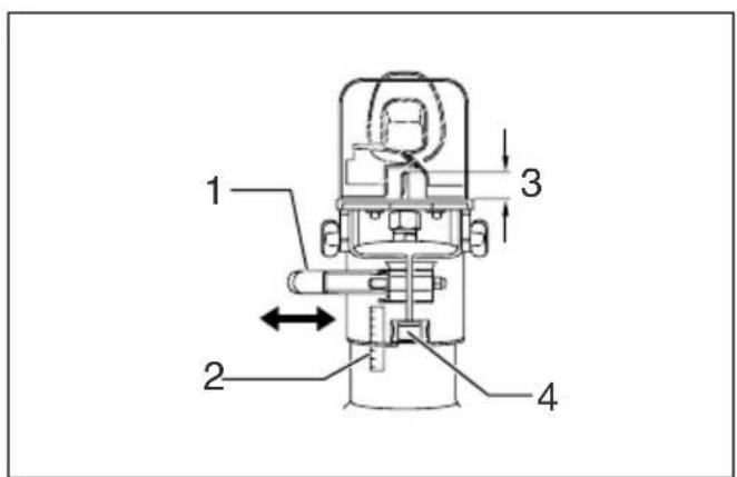
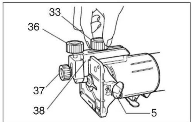
Adjusting bit protrusion (Fig. 1)
To adjust the bit protrusion, loosen the lever and move the tool base up or down as desired by turning the adjusting roller. After adjusting, tighten the lever firmly to secure the tool base.
Adjusting angle of tool base (Fig. 2)
Loosen the wing bolts and adjust the angle of the tool base ( 5^ per graduation) to obtain the desired cutting angle.
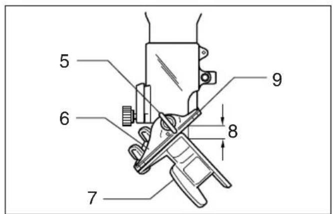
Adjusting amount of chamfering
To adjust the amount of chamfering, loosen the wing nuts and adjust the trimmer shoe.
CAUTION:
- With the tool unplugged and switch in the "OFF" position, rotate the collet nut on the tool several times to be sure that the bit turns freely and does not contact the base or trimmer shoe in any way.
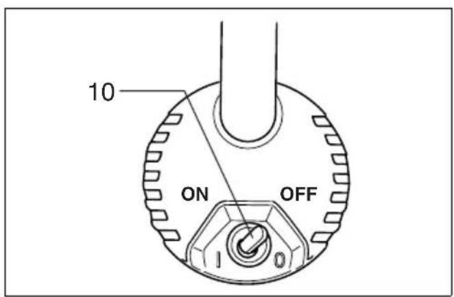
Switch action (Fig. 3)
CAUTION:
- Before plugging in the tool, always be sure that the tool is switched off.
To start the tool, move the switch lever to the I (ON) position. To stop the tool, move the switch lever to the O (OFF) position.
Electronic function
For model 3708FC only
The tool equipped with electronic function are easy to operate because of the following features.
Constant speed control
Electronic speed control for obtaining constant speed. Possible to get fine finish, because the rotating speed is kept constant even under load condition.
Soft start
Soft-start feature minimizes start-up shock, and makes the tool start smoothly.
Lighting up the lamps
For model 3708F/3708FC only
CAUTION:
- Do not look in the light or see the source of light directly.
To turn on the lamp, start the tool. Then, the lamp lights up the top of the bit. To turn it off, stop the tool.
NOTE:
- Use a dry cloth to wipe the dirt off the lens of lamp. Be careful not to scratch the lens of lamp, or it may lower the illumination.
ASSEMBLY
CAUTION:
- Always be sure that the tool is switched off and unplugged before carrying out any work on the tool.
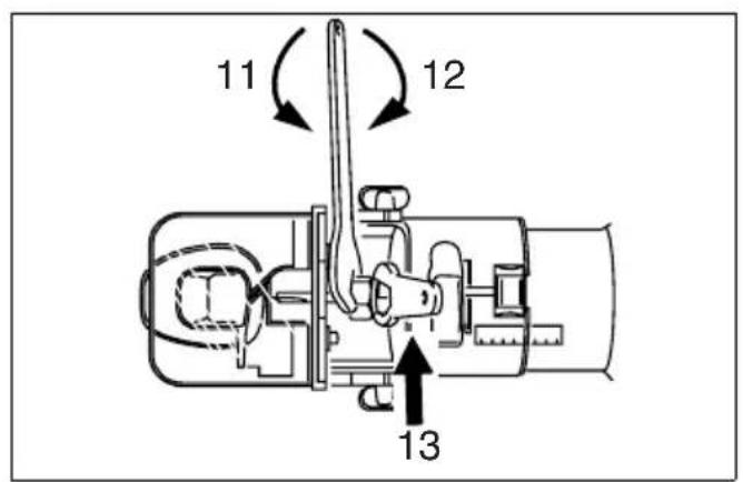
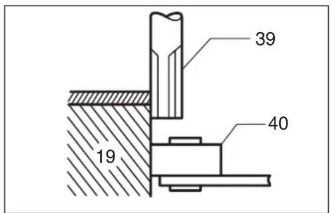
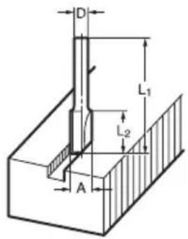
Installing or removing trimmer bit (Fig. 4)
CAUTION:
- Do not tighten the collet nut without inserting a bit, or the collet cone will break.
- Use only the wrenches provided with the tool.
Insert the bit all the way into the collet cone and tighten the collet nut securely with the two wrenches.
To remove the bit, follow the installation procedure in reverse.
Installing trimmer shoe (after it has been removed from the tool) (Fig. 5)
NOTE:
- The trimmer shoe is factory installed on the tool.
Use the bolts, wing nuts, spring washers and flat washers to install the trimmer shoe as shown in Fig. 5.
OPERATION
CAUTION:
- Always be sure that the tool is switched off and unplugged before removing or installing the trimmer base.
- Adjust the lever tightening strength of the trimmer base using its nut to obtain a suitable tightening strength for your tool. After adjusting, make sure the trimmer base is secured to the tool. Dislocation of the trimmer base may cause personal injuries.
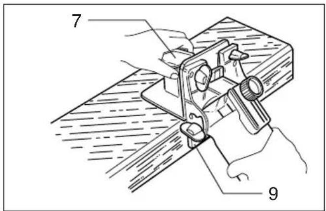
Turn the tool on without the bit making any contact with the workpiece and wait until the bit attains full speed. Then move the tool over the workpiece surface, keeping the tool base and trimmer shoe flush with the sides of the workpiece. (Fig. 6)
NOTE:
- This tool can be used as a conventional trimmer when you remove the trimmer shoe.
When doing edge cutting, the workpiece surface should be on the left side of the bit in the feed direction. (Fig. 7)
NOTE:
- Moving the tool forward too fast may cause a poor quality of cut, or damage to the bit or motor. Moving the tool forward too slowly may burn and mar the cut. The proper feed rate will depend on the bit size, the kind of workpiece and depth of cut. Before beginning the cut on the actual workpiece, it is advisable to make a sample cut on a piece of scrap lumber. This will show exactly how the cut will look as well as enable you to check dimensions.
- When using the trimmer shoe, the straight guide or the trimmer guide, be sure to keep it on the right side in the feed direction. This will help to keep it flush with the side of the workpiece. (Fig. 8)
CAUTION:
- Since excessive cutting may cause overload of the motor or difficulty in controlling the tool, the depth of cut should not be more than 3 mm at a pass when cutting grooves. When you wish to cut grooves more than 3 mm deep, make several passes with progressively deeper bit settings.
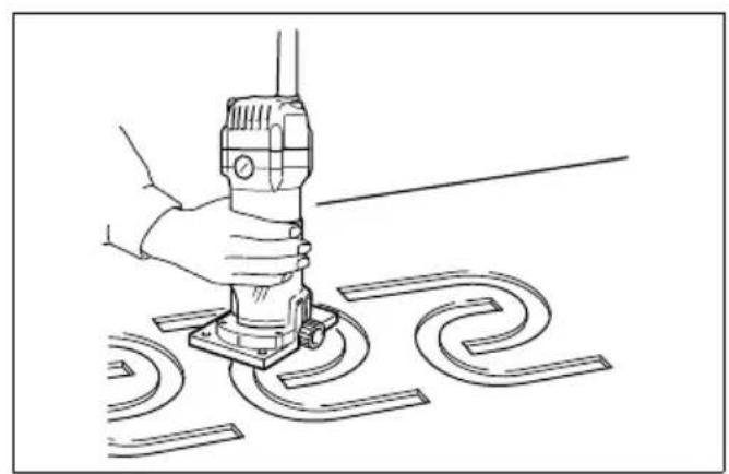
Templet guide
The templet guide provides a sleeve through which the bit passes, allowing use of the trimmer with templet patterns. (Fig. 9)
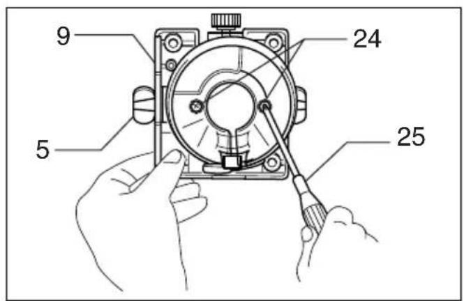
Remove the tool base from the tool. Loosen the wing bolts and secure the tool base horizontally. Loosen the two screws on the tool base. (Fig. 10)
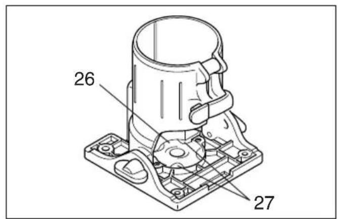
Place the templet guide on the tool base. There are four convex portions on the templet guide. Secure two of the four convex portions using the two screws. Install the tool base on the tool. (Fig. 11)
Secure the templet to the workpiece. Place the tool on the templet and move the tool with the templet guide sliding along the side of the templet. (Fig. 12)
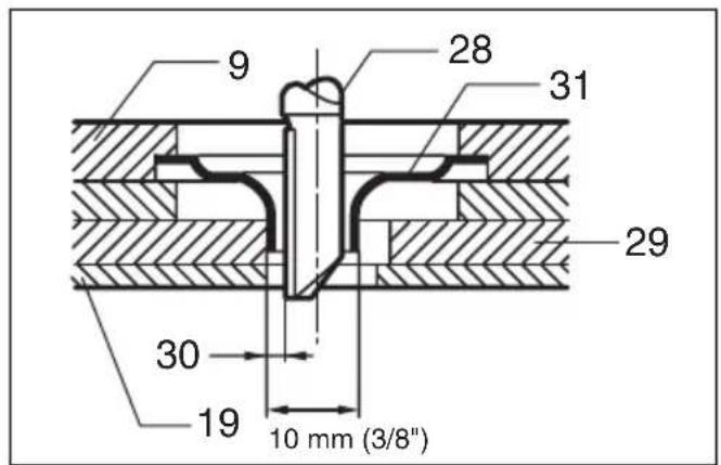
NOTE:
- The workpiece will be cut a slightly different size from the templet. Allow for the distance (X) between the router bit and the outside of the templet guide. The distance (X) can be calculated by using the following equation:
Distance (X) = (outside diameter of the templet guide – router bit diameter) / 2
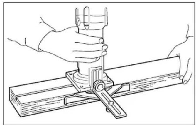
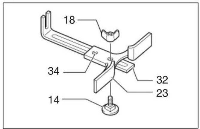
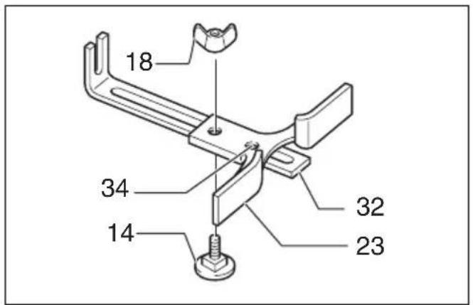
Straight guide (optional accessory)
The straight guide is effectively used for straight cuts when chamfering or grooving. (Fig. 13)
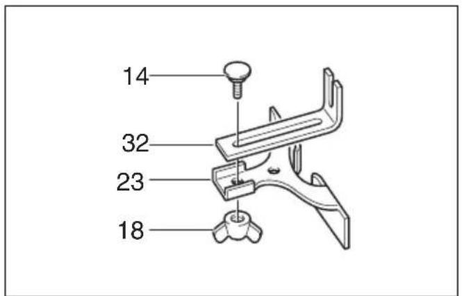
Attach the guide plate to the straight guide with the bolt, the wave washer, the flat washer and the wing nut. (Fig. 14)
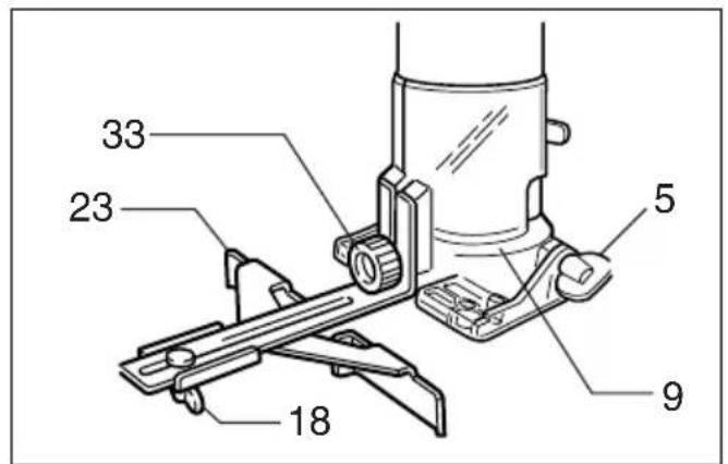
Loosen the wing nut and secure the tool base horizontally.
Attach the straight guide with the clamp screw (A). Loosen the wing nut on the straight guide and adjust the distance between the bit and the straight guide. At the desired distance, tighten the wing nut securely. (Fig. 15) When cutting, move the tool with the straight guide flush with the side of the workpiece.
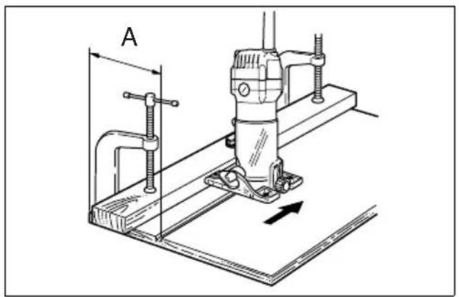
If the distance (A) between the side of the workpiece and the cutting position is too wide for the straight guide, or if the side of the workpiece is not straight, the straight guide cannot be used. In this case, firmly clamp a straight board to the workpiece and use it as a guide against the trimmer base. Feed the tool in the direction of the arrow. (Fig. 16)
Circular work
Circular work may be accomplished if you assemble the straight guide and guide plate as shown in Fig. 17 or 18. Min. and max. radius of circles to be cut (distance between the center of circle and the center of bit) are as follows:
Min.: 70 mm
Max.: 221 mm
Fig. 17 for cutting circles between 70 mm and 121 mm in radius.
Fig. 18 for cutting circles between 121 mm and 221 mm in radius.
NOTE:
- Circles between 172 mm and 186 mm in radius cannot be cut using this guide.
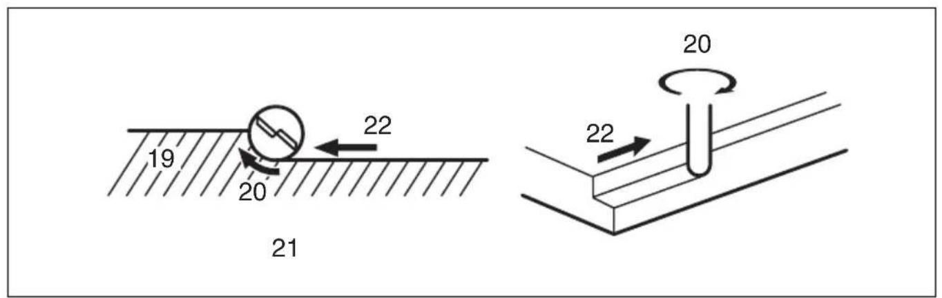
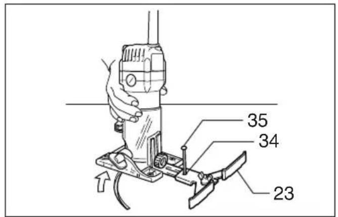
Align the center hole in the straight guide with the center of the circle to be cut. Drive a nail less than 6 mm in diameter into the center hole to secure the straight guide. Pivot the tool around the nail in clockwise direction. (Fig. 19)
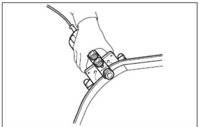
Trimmer guide
Trimming, curved cuts in veneers for furniture and the like can be done easily with the trimmer guide. The guide roller rides the curve and assures a fine cut. (Fig. 20)
Loosen the wing bolts and secure the tool base horizontally.
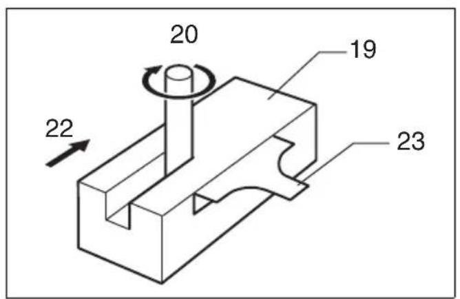
Install the trimmer guide on the tool base with the clamp screw (A). Loosen the clamp screw (B) and adjust the distance between the bit and the trimmer guide by turning the adjusting screw (1 mm per turn). At the desired distance, tighten the clamp screw (B) to secure the trimmer guide in place. (Fig. 21)
When cutting, move the tool with the guide roller riding the side of the workpiece. (Fig. 22)
MAINTENANCE
CAUTION:
- Always be sure that the tool is switched off and unplugged before attempting to perform inspection or maintenance.
- Never use gasoline, benzine, thinner, alcohol or the like. Discoloration, deformation or cracks may result.
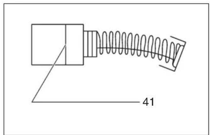
Replacing carbon brushes
Remove and check the carbon brushes regularly. Replace when they wear down to the limit mark. Keep the carbon brushes clean and free to slip in the holders. Both carbon brushes should be replaced at the same time. Use only identical carbon brushes. (Fig. 23)
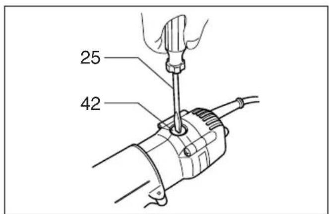
Use a screwdriver to remove the brush holder caps. Take out the worn carbon brushes, insert the new ones and secure the brush holder caps. (Fig. 24)
To maintain product SAFETY and RELIABILITY, repairs, any other maintenance or adjustment should be performed by Makita Authorized Service Centers, always using Makita replacement parts.
OPTIONAL ACCESSORIES
CAUTION:
- These accessories or attachments are recommended for use with your Makita tool specified in this manual. The use of any other accessories or attachments might present a risk of injury to persons. Only use accessory or attachment for its stated purpose.
If you need any assistance for more details regarding these accessories, ask your local Makita Service Center.
- Straight & groove forming bits
- Edge forming bits
• Laminate trimming bits - Straight guide assembly
- Trimmer guide assembly
- Trimmer base assembly (For chamfering with straight bit)
- Trimmer shoe
- Templet guide
- Collet cone 6 mm
• Collet cone 6.35 mm (1/4") - Wrench 10
- Wrench 17
NOTE:
- Some items in the list may be included in the tool package as standard accessories. They may differ from country to country.
ENG905-1
Noise
The typical A-weighted noise level determined according to EN60745:
Model 3708, 3708F
Sound pressure level ( L_pA ): 80 dB (A)
Uncertainty (K): 3 dB (A)
The noise level under working may exceed 80 dB (A).
Model 3708FC
Sound pressure level ( L_pA ): 76 dB (A)
Uncertainty (K): 3 dB (A)
The noise level under working may exceed 80 dB (A).
Wear ear protection
ENG900-1
Vibration
The vibration total value (tri-axial vector sum) determined according to EN60745:
Work mode: rotation without load
Vibration emission (ah): 2.5 m/s² or less
Uncertainty (K): 1.5 m/s
ENG901-1
- The declared vibration emission value has been measured in accordance with the standard test method and may be used for comparing one tool with another.
- The declared vibration emission value may also be used in a preliminary assessment of exposure.
WARNING:
- The vibration emission during actual use of the power tool can differ from the declared emission value depending on the ways in which the tool is used.
- Be sure to identify safety measures to protect the operator that are based on an estimation of exposure in the actual conditions of use (taking account of all parts of the operating cycle such as the times when the tool is switched off and when it is running idle in addition to the trigger time).
For European countries only
ENH101-15
EC Declaration of Conformity
We Makita Corporation as the responsible manufacturer declare that the following Makita machine(s):
Designation of Machine:
Trimmer
Model No./ Type: 3708, 3708F, 3708FC
are of series production and
Conforms to the following European Directives: 2006/42/EC
And are manufactured in accordance with the following standards or standardised documents: EN60745
The technical documentation is kept by our authorized representative in Europe who is:
Makita International Europe Ltd.
Michigan Drive, Tongwell,
Milton Keynes, Bucks MK15 8JD, England
30.1.2009

Tomoyasu Kato
Director
Makita Corporation
3-11-8, Sumiyoshi-cho,
Anjo, Aichi, 446-8502, JAPAN
Descriptif
Michigan Drive, Tongwell,
Milton Keynes, Bucks MK15 8JD, Angleterre
30.1.2009

3-11-8, Sumiyoshi-cho,
Anjo, Aichi, 446-8502, JAPAN
Übersicht
Michigan Drive, Tongwell,
Milton Keynes, Bucks MK15 8JD, England
30.1.2009

Tomoyasu Kato Direktor
Makita Corporation
3-11-8, Sumiyoshi-cho,
Anjo, Aichi, 446-8502, JAPAN
Visione generale
Michigan Drive, Tongwell,
Milton Keynes, Bucks MK15 8JD, England
30.1.2009

Tomoyasu Kato
Amministratore
Makita Corporation
3-11-8, Sumiyoshi-cho,
Anjo, Aichi, 446-8502, JAPAN
OPTIONELE ACCESSOIRES
LET OP:
Michigan Drive, Tongwell,
Milton Keynes, Bucks MK15 8JD, Engeland
30.1.2009

3-11-8, Sumiyoshi-cho,
Anjo, Aichi, 446-8502, JAPAN
Michigan Drive, Tongwell,
Milton Keynes, Bucks MK15 8JD, Inglaterra
30.1.2009

Tomoyasu Kato
Director
Makita Corporation
3-11-8, Sumiyoshi-cho,
Anjo, Aichi, 446-8502, JAPAN
Explicação geral
Michigan Drive, Tongwell,
Milton Keynes, Bucks MK15 8JD, Inglaterra
30.1.2009

Tomoyasu Kato
Director
Makita Corporation
3-11-8, Sumiyoshi-cho,
Anjo, Aichi, 446-8502, JAPAN
Michigan Drive, Tongwell,
Milton Keynes, Bucks MK15 8JD, England
30.1.2009

Tomoyasu Kato
Direktør
Makita Corporation
3-11-8, Sumiyoshi-cho,
Anjo, Aichi, 446-8502, JAPAN
Michigan Drive, Tongwell,
Milton Keynes, Bucks MK15 8JD, England (Aγγλία)
30.1.2009

Tomoyasu Kato
Διευθυντής
Makita Corporation
3-11-8, Sumiyoshi-cho,
Anjo, Aichi, 446-8502, JAPAN
Trimmer bits/Fraises d'affleurage/Schneidfräser/Frese rifilatori/Diverse bits voor de frees/Fresas de rebordeadoras/Fresas para recortes/Fræseværktøj/Aixmės ξακρίσματος
005116
005117
"U" Grooving bit Fraise à rainurer en "U"
U-Nutfräser Fresa a incastro a "U"
U-groef frezen
Fresa ranuradora en "U"
005118
"V" Grooving bit
005120
Drill point flush trimming bit
Fraise à affleurer
Bündigfräser
Drill point double flush trimming bit
005125
Corner rounding bit Fraise à arrondir Rundkantenfräser Fresa a raggio
005126
005129
Cove beading bit
005130
Ball bearing flush trimming bit
005131
Ball bearing corner rounding bit
005132
Ball bearing chamfering bit
005133
Ball bearing beading bit
005134
Ball bearing cove beading bit
005135
Ball bearing roman ogee bit