
No 526 - Receiver Mark Levinson - Free user manual and instructions
Find the device manual for free No 526 Mark Levinson in PDF.
| Product Type | Dual mono stereo preamplifier |
| Brand | Mark Levinson |
| Model | No 526 |
| Category | Receiver |
| Dimensions (W x D x H) | 438 x 485 x 101 mm (without feet: 88 mm) |
| Weight | 18.6 kg |
| Power supply | 100 V, 115 V, or 230 V AC, 50/60 Hz (factory set) |
| Power consumption during operation | 88 W (idle) |
| Power consumption in standby | 0.4 W (Green mode), 5 W (Eco), 75 W (Normal) |
| Analog inputs | 2 balanced (XLR), 3 unbalanced (RCA), 1 phono (RCA with ground) |
| Digital inputs | 1 AES/EBU (XLR), 2 coaxial (RCA), 2 optical (Toslink), 1 asynchronous USB (type B) |
| Analog outputs | 1 balanced pair (XLR), 1 unbalanced pair (RCA), 1 headphone 6.35 mm |
| Main features | Balanced Pure Path signal path, R-2R 15-bit volume control, Precision Link DAC ESS Sabre 32-bit, Clari-Fi, 80 Hz high-pass filter, PSA mode, phono stage with adjustable gain, included remote control |
| Control connectors | Ethernet, RS-232, IR, 12 V trigger (2 outputs, 1 input) |
| Construction | Steel and extruded aluminum chassis, black with silver trim |
| Maintenance | Clean with a soft dry cloth. Do not use solvents. Ensure adequate ventilation. |
| Safety | Unplug before cleaning or moving. Do not block vents. Use a grounded outlet. |
| Spare parts and repairability | Contact an authorized Mark Levinson dealer. Replaceable fuses. |
| General information | Handcrafted in the USA. Trademark of HARMAN. |
Frequently Asked Questions - No 526 Mark Levinson
User questions about No 526 Mark Levinson
0 question about this device. Answer the ones you know or ask your own.
Ask a new question about this device
Download the instructions for your Receiver in PDF format for free! Find your manual No 526 - Mark Levinson and take your electronic device back in hand. On this page are published all the documents necessary for the use of your device. No 526 by Mark Levinson.
USER MANUAL No 526 Mark Levinson
Special Design Features 2
Installation Considerations 3
Unpacking, Placement and Ventilation, Power Requirements, Operating States
Getting Started 5
Front-Panel Overview: Rear Panel, Remote Control Overview
Quick Setup and Listen 11
Remote Control, Initial Connections
Setup Menu 14
Setup Menu Navigation, Input Setup, Volume Control, Power Management and Display, Advanced, Output
SSP Setup 19
Troubleshooting 21
Specifications 23
ABOUT THIS DOCUMENT
This manual will enable you to configure and finely tailor the behavior and performance of the preamp to fit your preferences and the particulars of your equipment and listening room. It is strongly recommended that you follow this manual in the order in which it is written so that you understand safety considerations before configuring this sophisticated preamplifier.
SPECIAL DESIGN FEATURES
Thank you for purchasing a N ^526 or N ^523 dual-monaural preamplifier. Combining Mark Levinson's unsurpassed analog performance with flexible system configuration and advanced digital and phono capabilities, these preamplifiers push the reproduction of source material to new levels of realism.
Architecture
The foundation of these preamplifiers is their proprietary Mark Levinson Pure Path discrete, direct-coupled, fully balanced, dual-monaural signal path with discrete, balanced R-2R ladder volume controls. They feature individual signal switching relays for each of their stereo inputs: two balanced (XLR) and three single-ended (RCA), plus phono; and six additional digital inputs on the N°526. Volume controls use discrete 15-bit R-2R ladders and low-noise analog switches for the widest possible bandwidth and maximum signal integrity. System integration and expansion are possible using the outputs, which can operate full-range or with a switchable fourth-order, 80Hz filter allowing for seamless integration into systems with powered subwoofers.
Audio Chassis
Building upon this superb analog platform, the N°526 adds equally outstanding digital audio capability. The Mark Levinson Precision Link D/A converter with nine individual power supplies, proprietary jitter elimination circuitry and fully balanced, discrete I/V circuitry forms the heart of the digital audio processing stage. Six digital audio inputs are provided including one AES/EBU, two coaxial and two optical plus a USB audio processor capable of asynchronous data transfer of high-resolution DSD and PCM at up to 192kHz, 32-bit resolution. For low-resolution audio formats, proprietary HARMAN Clari-Fi® music restoration technology reconstructs information and bandwidth lost in compressed file formats. System integration and communication ports include Ethernet, USB, RS-232, IR input, and 12V trigger input and output. A system IR remote control is included.
Construction
The chassis of the preamplifiers utilizes modular architecture to isolate critical low-level analog and digital circuitry from the power supplies. The 6000-series extruded aluminum and steel chassis features internal heatsinks and Mark Levinson's iconic appearance of black with silver trim.
Features
- Mark Levinson Pure Path proprietary discrete, direct coupled, fully balanced, dual-monaural signal path
- Discrete, balanced R-2R ladder volume controls
- Digital inputs: USB asynchronous, AES/EBU balanced, two Toslink optical, two Coaxial (N526 only)
- Analog inputs: two balanced, three unbalanced, phono with grounding pin
- Analog outputs: XLR balanced pair, RCA unbalanced pair, 1/4-inch (6.3mm) headphone
- Supports high-resolution formats including 32-bit, 192kHz PCM and double-speed DSD (N°526 only)
- Mark Levinson Precision Link DAC featuring the renowned ESS Sabre 32-bit processor (N°526 only)
- Pure Phono stage with selectable gain, infrasonic filter, resistive and capacitive-loading settings
- Selectable fourth-order, 80 Hz high-pass filter allows seamless integration of subwoofer
- SSP Mode for pass-through connection to a multichannel surround processor
- Mark Levinson Main Drive circuit for headphone playback: front-panel jack with integral Class A amplifier
- Designed and handcrafted in the USA
INSTALLATION CONSIDERATIONS
UNPACKING
When unpacking your preamplifier:
- Save all packing materials in case you need to ship your preamp in the future.
- Inspect your preamp for signs of damage during shipment. If you discover damage, contact your authorized Mark Levinson dealer for assistance in making appropriate claims.
- Please register your preamplifier within 15 days of purchase at marklevinson.com.
- Retain your original, dated sales receipt as proof of warranty coverage.
- Remove the accessory box from the shipping carton. Make sure that all of the items listed below are included. If any are missing, contact your authorized Mark Levinson dealer.
o IEC power cord (terminated according to the region to which the unit is shipped)
o Remote control with preinstalled batteries
o Phillips screwdriver (for replacing remote batteries)
o Pair white gloves (for use during unpacking and initial setup)
o Documentation
PLACEMENT AND VENTILATION
- Install the preamplifier on a shelf with several inches of clearance above it to ensure proper ventilation. Do NOT install the preamplifier inside of an enclosed cabinet or rack.
- Ensure that you install the preamplifier on a solid, flat and level surface.
- Install the preamplifier as close as possible to associated audio components to keep interconnecting cables as short as possible.
- Select a dry, well-ventilated location that is out of direct sunlight.
- DO NOT expose the preamp to high temperatures, humidity, steam, smoke, dampness, or excessive dust.
- DO NOT block chassis ventilation holes.
POWER REQUIREMENTS
The preamplifier is configured at the factory for 100, 115, or 230 VAC power operation at 50Hz or 60Hz. Before operating, ensure that the power label on the rear panel near the AC input connector indicates the correct operating voltage. A detachable IEC power cable intended for use in the region where the unit is sold is included.
Connection to an AC voltage other than that for which the unit is intended can create a safety and fire hazard and may damage the unit. If you have any questions about the voltage requirements for your preamplifier or about the line voltage in your area, contact your authorized Mark Levinson dealer before plugging the unit into an AC power outlet.
WARNING! MAKE SURE all components in the audio system are properly grounded. Do NOT defeat the safety purpose of polarized or grounding-type plugs with "ground-lifter" or "cheater" adapters. Doing so may cause dangerous voltage to build up between components, which may result in personal injuries and/or product damage.
You should unplug the preamplifier from the AC wall outlet during lightning storms and extended periods of non-use.
CAUTION: BEFORE moving the unit, make sure it is powered off by removing the power cord from the AC power outlet and the unit's rear panel.
OPERATING STATES
The preamplifier has three operating states:
Off: The AC mains power is disconnected by using the rear-panel Power switch or by removing the power cord from the rear panel.
Standby: The Standby mode has three settings that can be selected via the Setup menu: Green, Power Save, and Normal.
Green: This mode removes power from almost all of the circuits, allowing the unit to be activated only via an IR control signal, a 5V - 12V trigger or a press of the Standby button. This mode provides maximum power conservation and is the factory-default Standby mode. In Green standby, the LED is dimmed.
PowerSave: This mode removes power from the audio circuits, but keeps the control circuitry powered and ready to receive commands from either the front panel controls, Ethernet, RS-232 or the remote control. This mode provides moderate power conservation. In Power Save standby, the LED is dimmed.
Normal: This mode shuts off the display and mutes its audio outputs, but keeps all of its control and audio circuits powered. This mode provides the least amount of power conservation but allows the audio circuits to remain warmed up to deliver optimal performance at all times. Power consumption: 67-72W.
On: The entire unit is powered up and all configured outputs are active.
The preamplifier has an Auto Off feature that automatically places it into the Standby mode after 20 minutes of no user control input or audio signal passing through the unit. The factory-default setting for the Auto Off feature is on (engaged). You can turn the Auto Off feature off (disengaged) in the Setup menu.
GETTING STARTED
FRONT-PANEL OVERVIEW: N°526 AND N°523
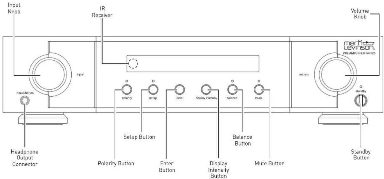
Front-panel controls/indicators
Input knob: Rotate this knob to select the desired input to send to the outputs. The name and volume level of the selected input are indicated on the display. (Note: the Input knob will bypass any input for which the Input Name Setup menu parameter has been set to "Unused.")
IR receiver: the IR receiver receives commands from the included remote control when the unit is not being controlled via its rear-panel IR Input connector (see Rear-Panel Overview for more information). Infrared communication requires line-of-sight between the remote and this "target" on the unit's front panel.
Headphone output connector: this 14 -inch (6.3mm) TRS phone plug connector provides a stereo signal that can directly drive most headphones. When the unit detects that headphones have been connected, the Balanced and Single-Ended outputs are automatically muted, and the Volume knob switches to control of the Headphone output level. When the unit detects the headphones have been disconnected, the Balanced and Single-Ended outputs are automatically unmuted, and the Volume knob returns to control of their level.
The balanced and single-ended outputs can be configured in the Setup menu as Fixed (for use with recording components or a second audio zone). When outputs are configured as Fixed, they are not affected by any of the front-panel controls.
Polarity button: pressing this button inverts the absolute polarity of the signal. The associated LED illuminates when the signal's polarity is inverted.
Setup button: press this button to display the Setup menu, which you can use to customize the preamp to suit your other system components, individual preferences and listening space. The Setup LED lights when the Setup menu is active.
Enter button: press this button to select or deselect a menu item when the Setup menu is displayed. When playing from a digital source, pressing the Enter button displays the sample rate, unless the PLL Lock is set to Wide.
Display Intensity button: Press this button to change the intensity of the front-panel display. Multiple presses of the Display Intensity button cycle through the available brightness levels: High, Medium, Low, and Off.
Balance button: press this button to enter adjustment of the left-to-right channel output balance (disabled if outputs are set to Fixed in the Setup menu). The Balance LED lights when the balance function is active.
NOTE: the Balance LED remains lit when the left-to-right balance of the Main outputs is offset. Headphone Balance can be adjusted independently of the Balanced or Single-Ended outputs.
Mute button: press this button to mute and unmute the level of the outputs by the amount determined in the Setup menu. The LED lights when the mute function is active.
Volume knob: turn this knob to adjust the volume level of the outputs. The minimum volume level is OFF; the maximum volume level is determined in the Setup menu. Whenever you select an input, the unit applies the volume offset selected for it in the Setup menu to the output volume level.
Standby button: press this button to put the unit into and out of the selected Standby mode. The LED illuminates when the unit is On. When the unit is in Standby mode, it flashes slowly, with brightness level to indicate Standby mode.
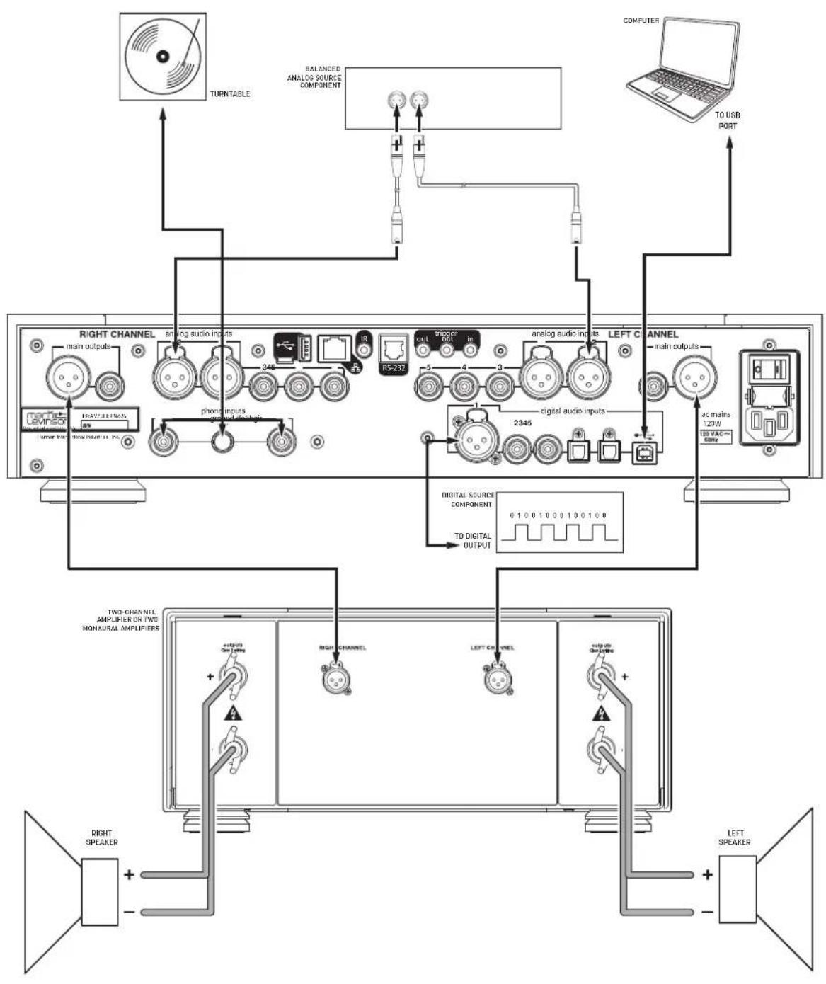
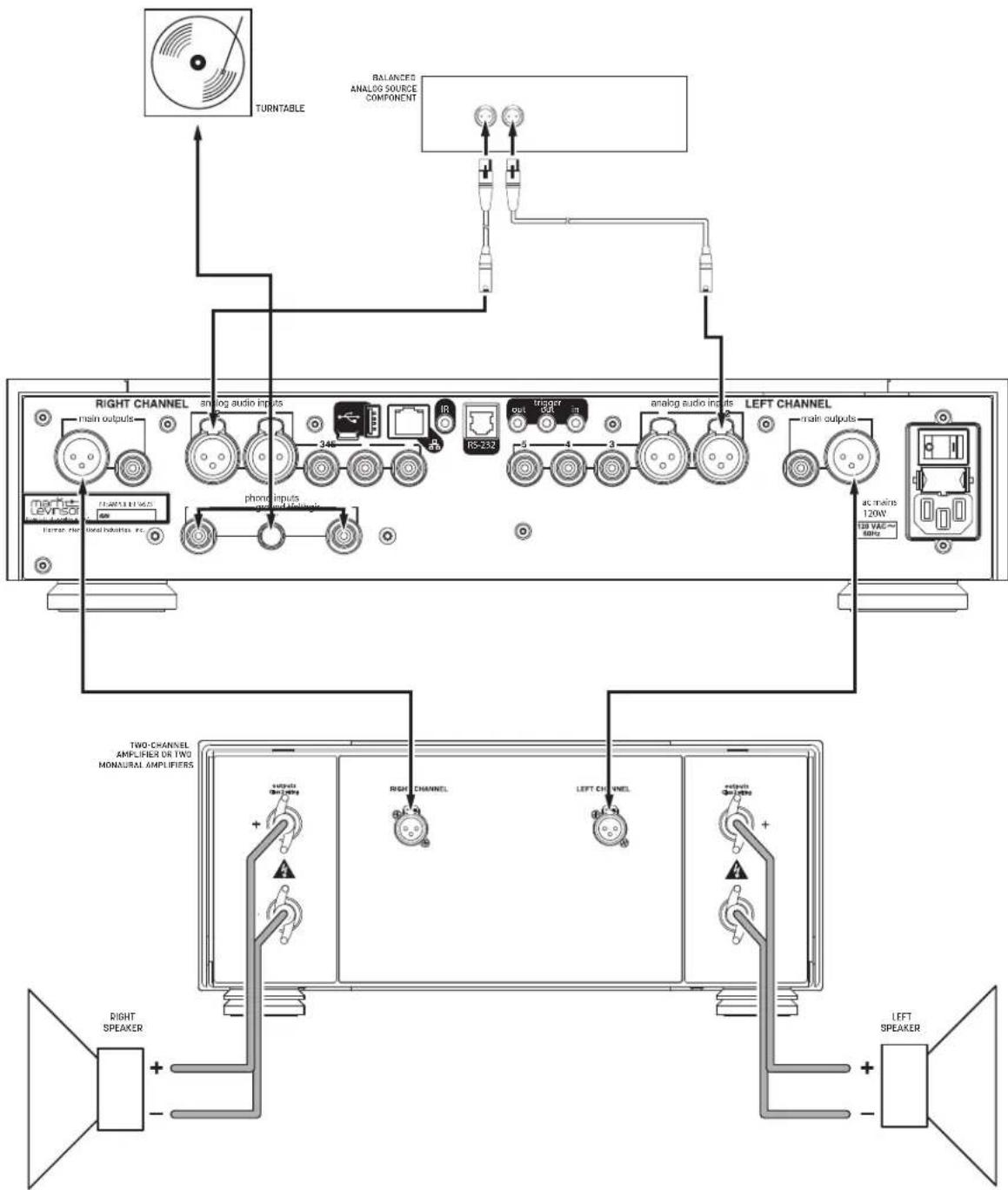
N°526 AND N°523 REAR PANEL OVERVIEW
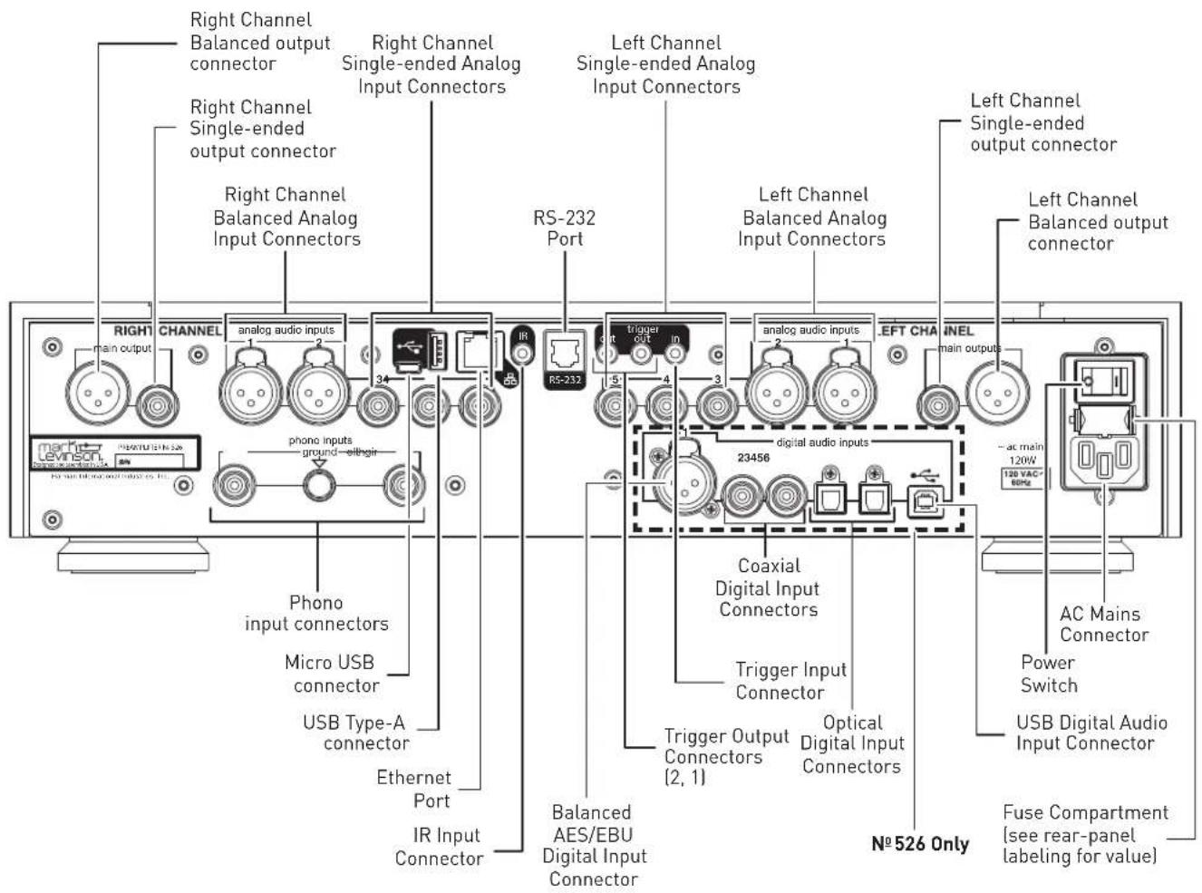
Output Connectors
Balanced output connectors: these XLR 3-pin connectors provide a line-level left-channel and right-channel signal that can be used to send the selected input to power amplifier inputs, a powered subwoofer, or to recording components. Mark Levinson recommends using the Balanced outputs as the primary output if your amplifiers offer balanced inputs.
Single-ended output connectors: these RCA connectors provide a line-level left-channel and right-channel signal that can be used to send the selected input to amplifier inputs, a powered subwoofer, to a second listening zone, or to recording components.
The Balanced and Single-ended outputs can be configured in the Setup menu as Fixed (for use with recording components or a second audio zone). When outputs are configured as Fixed, they are not affected by any of the front-panel controls.
By default the Balanced and Single-ended outputs are confirmed as as Variable. When so configured, the Balanced and Single-Ended outputs will follow the settings of the Volume, Balance and Mute controls. The Headphone output is always variable.
Additionally, if you would like to include a powered subwoofer in your system, you can restrict the low frequencies sent to your main speakers by engaging the unit's 24dB-per-octave Butterworth 4th-order 80Hz high-pass filter, which can be applied to either the Balanced or Single-Ended outputs.
For further information on configuring these parameters, see the Setup Menu section of this manual.
Input Connectors
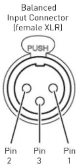
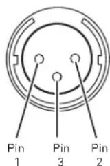
Balanced analog input connectors (1, 2): these connectors accept left-channel and right-channel balanced input signals from source components with balanced (male XLR) output connectors.
Balanced connector pin assignments:
- Pin 1: Signal ground
- Pin 2: Signal + (non-inverting) "hot"
- Pin 3: Signal – (inverting) "cold"
Balanced
Output Connector
(male XLR)
Single-ended input connectors [3, 4, 5]: these connectors accept left-channel and right-channel single-ended (unbalanced) input signals from source components without balanced output connectors. Mark Levinson recommends using balanced connections whenever possible.
Phono input connectors: these connectors accept left-channel and right-channel input signals from turntables with moving-magnet or moving-coil cartridges that do not have a built-in preamplifier. Connect the turntable output cable's grounding terminal to the preamplifier's ground pin by loosening the threaded collar, inserting the terminal, and tightening the collar using your fingers only. Do not tighten the ground pin collar with tools.
N°526 only:
Digital input connectors: the N-526 has six digital audio input connectors:
• One AES/EBU Balanced XLR, numbered 1
o Mark Levinson recommends using the Balanced connection whenever possible.
- Two Coaxial S/PDIF RCA, numbered 2 and 3
- Two Optical S/PDIF TOSLINK, numbered 4 and 5
- One Asynchronous USB Type B, numbered 6 o The USB connection is used for streaming audio from your computer.
Control Connectors
Micro USB connector: this connection enables the unit to be connected to a computer for internal webpage discovery. When the unit is connected to power and network, the preamplifier will mount to the PC as a mass-storage device containing a hyperlink to its internal web page for configuration and status monitoring.
USB Type-A connector: the connector is for attaching a USB flash drive containing unit software update, or for importing and exporting setup configurations. Further information on software updates is available from the Setup Menu: Advanced section of this manual.
Ethernet connector: This connector accepts a Cat5 or higher cable for connection to a home network. For information on how to configure and use the Ethernet port, see Setup Menu: Advanced section of this manual.
IR input connector: this 1/8-inch (3.5mm) connector accepts IR (infrared) control signals from other equipment. (does not work with extenders)
NOTE: that the IR input connector does not provide power for IR extender modules.
RS-232 connector: this RJ-11 connector provides serial control through a standard RS-232 connection.
Trigger output connectors: these 1/8-inch (3.5mm) TS phone plug connectors can be used to activate other components in the audio system and listening room, such as amplifiers, lights, and window shades. A 12V 100mA DC signal is output whenever the unit is on. The trigger can also be pulsed and delayed. (See illustration)
Trigger phone plug connector pin assignments:
- Tip: +
- Sleeve: -

Trigger input connector: this 1/8-inch (3.5mm) TS phone plug connector can be connected to the trigger output of another system component or control system that supplies a trigger voltage. Whenever the unit detects a voltage between 5V and 12V DC at this connection, it will turn On from Standby. When the trigger signal at this connection ceases, the unit will enter the selected Standby mode. (See illustration)
AC Mains connector: This connector provides AC power to the unit when the supplied power cord is connected from it to an AC electrical outlet. Unplug the preamplifier from the AC wall outlet during lightning storms and extended periods of non-use.
Power switch: this mechanical switch turns the unit's power supply on or off. During normal operation, do not use the Power switch to power off the unit; instead, use the Standby button.
REMOTE CONTROL OVERVIEW
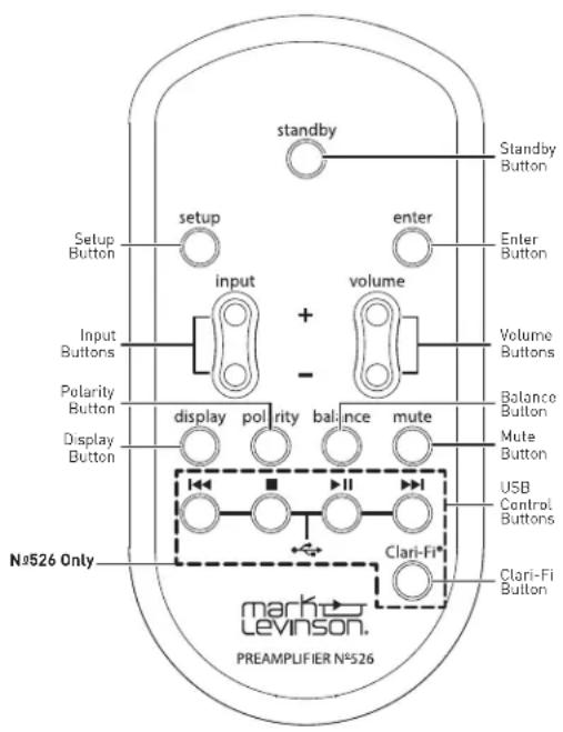
Standby button: press this button to put the unit into and out of the selected Standby mode.
Input buttons: press these buttons to select the desired input. The name and volume level of the selected input are indicated on the front-panel display.
Volume buttons: press these buttons to adjust the volume level of the Balanced outputs--and the Single-Ended outputs if you have set them to Variable in the Setup menu, or the Headphone output if you have connected headphones. The minimum volume level is OFF; the maximum volume level is determined in the Setup menu.
Whenever you select an input, the unit applies the volume offset selected for it in the Setup menu to the Main output volume level (and to the Line output volume level if you have set it to Variable in the Setup menu).
Setup button: press this button to display the Setup menu, which you can use to customize the preamplifier to suit your individual preferences, listening space and other system components. The Setup LED on the front panel illuminates when the Setup menu is active.
Mute button: press this button to mute and unmute the level of the Balanced outputs--and the Single-Ended outputs if you have set them to Variable in the Setup menu, or the Headphone output if you have connected headphones--by the amount determined in the Setup menu. The Mute LED on the front panel lights when the mute function is active.
Enter button: press this button to select or deselect a menu item when the Setup menu is displayed.
N°526 only: press the Enter button to display the Sampling rate when one of the digital inputs is selected (this function is disabled when PLL Lock is set to Wide).
Balance buttons: press this button to edit the left-to-right channel balance sent to the Balanced outputs, Single-Ended outputs if set to Variable in the Setup Menu, or Headphone output if headphones are connected. The Balance LED illuminates when Balance adjustment is active. It also illuminates when Balance adjustment is inactive if the left-to-right channel balance is offset from 0.
Clari-Fi® button (N°526 only): pressing this button activates or deactivates HARMAN Clari-Fi music restoration technology. After turning Clari-Fi on, the unit will display the Clari-Fi Intensity menu, which can be adjusted from 0 to 9 using the Volume buttons.
Clari-Fi can be applied to digital input sources only.
Polarity button: pressing this button inverts the absolute polarity of the signal at the outputs. The Polarity LED on the front panel illuminates when the signal's polarity is inverted.
Display button: press this button to change the intensity of the front-panel display. Multiple presses of the Display button cycle through the available brightness levels: High, Medium, Low, Off. If the display is Off and the unit is On, press the Display button to turn the display on.
USB transport control buttons (N°526 only): when the USB Type-B input is selected and software that supports external USB controls (such as Apple iTunes®), these buttons control playback.
QUICK SETUP AND LISTEN
REMOTE CONTROL
Your remote control comes with two preinstalled AAA alkaline batteries. To replace the batteries, remove the remote control's battery cover using the included screwdriver, insert the batteries and replace the battery cover. Be sure to observe proper battery polarity.
When using the remote control, aim it toward the front-panel IR receiver. Make sure that no objects, such as furniture, block the remote's view of the receiver. Bright lights, fluorescent lights, and plasma video displays may interfere with the function of the remote.
- The remote has a range of about 17 feet (5m), depending on the lighting conditions.
- You can use the remote at an angle of up to 45^ .
- Placing the unit behind tinted glass will reduce the remote control's effective range.
INITIAL CONNECTIONS
CAUTION: Before making connections, make sure the preamplifier and all associated components are powered off and disconnected from electrical outlets.
- Connect your amplifier(s) to the preamplifier's output connectors. Mark Levinson recommends using the Balanced output connectors if your amplifier(s) have balanced input connectors. Otherwise, use the Single-ended output connectors.
- Connect analog source components' outputs to the preamp's analog audio inputs. Mark Levinson recommends using Balanced connections whenever they are available.
3.(N°526 only) Connect digital source components' outputs to the preamp's digital audio inputs. If you are connecting a computer via USB, download and install the USB driver software from the product web page at marklevinson.com, under the Downloads tab.
- Connect the supplied power cable to the preamp's AC Mains connector and into an electrical outlet. Turn the rear-panel Power switch on the preamp to On, and turn on all associated components.
- Press the front-panel Standby button or the Standby button on the remote control.
- Turn the Input knob or press the Input buttons on the remote to select the input that corresponds to an input connector to which you connected a source component.
- Make sure the preamp's volume is set to a reasonable level. It is best to start low and turn up to avoid unintentionally damaging your equipment. Begin playing the selected source device.
flowchart
graph TD
    A["COMPUTER"] --> B["TO USB PORT"]
    B --> C["RIGHT CHANNEL"]
    C --> D["analog audio inputs"]
    C --> E["RS-232"]
    C --> F["phonic inputs"]
    C --> G["ground devices"]
    C --> H["digital audio inputs"]
    C --> I["ALPHA/REF/MAN"]
    C --> J["TV/AC 120W"]
    C --> K[TOR/TH/TH/TH/TH/TH/TH/TH/TH/TH/TH/TH/TH/TH/TH/TH/TH/TH/TH/TH/TH/TH/TH/TH/TH/TH/TH/TH/TH/TH/TH/TH/TH/TH/TH/TH/TH/TH/TH/TH/TH/TH/TH/TH/TH/TH/TH/TH/TH/TH/TH/Th/TH/TH/TH/TH/TH/TH/TH/TH/TH/TH/TH/TH/TH/TH/TH/TH/TH/TH/TH/TH/TH/TH/TH/TH/TH/TH/TH/TH/TH/TH/TH/TH/TH/TH/TH/TH/TH/TH/TH/TH/TH/TH/TH/TH/TH/TH/TH/TH/TH/<nl>
flowchart
graph TD
    A["RIGHT CHANNEL"] --> B["analog audio inputs"]
    B --> C["34K"]
    C --> D["RS-232"]
    D --> E["out"]
    E --> F["3"]
    F --> G["4"]
    G --> H["3"]
    H --> I["analog audio inputs"]
    I --> J["RS-232"]
    J --> K["5"]
    K --> L["4"]
    L --> M["3"]
    M --> N["analog audio inputs"]
    N --> O["RS-232"]
    O --> P["5"]
    P --> Q["4"]
    Q --> R["3"]
    R --> S["analog audio inputs"]
    S --> T["RS-232"]
    T --> U["5"]
    U --> V["4"]
    V --> W["3"]
    W --> X["analog audio inputs"]
    X --> Y["RS-232"]
    Y --> Z["5"]
    Z --> AA["4"]
    AA --> AB["3"]
    AB --> AC["analog audio inputs"]
    AC --> AD["RS-232"]
    AD --> AE["5"]
    AE --> AF["4"]
    AF --> AG["3"]
    AG --> AH["analog audio inputs"]
    AH --> AI["RS-232"]
    AI --> AJ["5"]
    AJ --> AK["4"]
    AK --> AL["3"]
    AL --> AM["analog audio inputs"]
    AM --> AN["RS-232"]
    AN --> AO["5"]
    AO --> AP["4"]
    AP --> AQ["3"]
    AQ --> AR["analog audio inputs"]
    AR --> AS["RS-232"]
    AS --> AT["5"]
    AT --> AU["4"]
    AU --> AV["3"]
    AV --> AW["analog audio inputs"]
    AW --> AX["RS-232"]
    AX --> AY["5"]
    AY --> AZ["4"]
    AZ --> BA["3"]
    BA --> BB["analog audio inputs"]
    BB --> BC["RS-232"]
    BC --> BD["5"]
    BD --> BE["4"]
    BE --> BF["3"]
    BF --> BG["analog audio inputs"]
    BG --> BH["RS-232"]
    BH --> BI["5"]
    BI --> BJ["4"]
    BJ --> BK["3"]
    BK --> BL["analog audio inputs"]
    BL --> BM["RS-232"]
    BM --> BN["5"]
    BN --> BO["4"]
    BO --> BP["3"]
    BP --> BQ["analog audio inputs"]
    BQ --> BR["RS-232"]
    BR --> BS["5"]
    BS --> BT["4"]
    BT --> BU["3"]
    BU --> BV["analog audio inputs"]
    BV --> BW["RS-232"]
SETUP MENU
SETUP MENU NAVIGATION
Pressing the Setup button displays the Setup menu on the preamplifier's front-panel display. When the Setup menu is active...
- use the Input knob to scroll through options,
- use the Enter button to select and deselect options,
- use the Volume knob to adjust parameters, and
- to move back a level in the menu structure or exit the Setup menu, press the Setup button repeatedly until the desired menu is shown in the display.
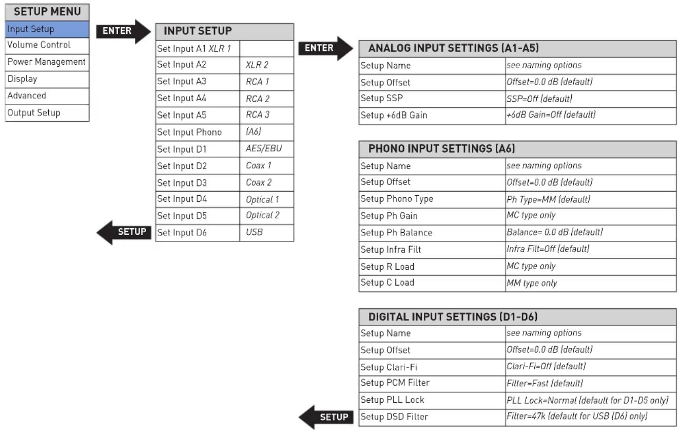
INPUT SETUP
flowchart
graph TD
    A["SETUP MENU"] --> B["ENTER"]
    B --> C["INPUT SETUP"]
    C --> D["ANALOG INPUT SETTINGS (A1-A5)"]
    D --> E["Setup Name"]
    D --> F["Setup Offset"]
    D --> G["Setup SSP"]
    D --> H["Setup +6dB Gain"]
    E --> I["PHONO INPUT SETTINGS (A6)"]
    F --> I
    G --> I
    H --> I
    I --> J["SETUP"]
    J --> K["DIGITAL INPUT SETTINGS (D1-D6)"]
    K --> L["Setup Name"]
    K --> M["Setup Offset"]
    K --> N["Setup Clari-Fi"]
    K --> O["Setup PCM Filter"]
    K --> P["Setup PLL Lock"]
    K --> Q["Setup DSD Filter"]
    L --> R["SETUP"]
    M --> R
    N --> R
    O --> R
    P --> R
    Q --> R
The Input Setup menu allows you to customize the following parameters for the selected input:
The following settings are available for all inputs.
Name: this option offers a choice of preset names for the selected input [CD, SACD™, DVD, Blu-ray™, DAC, EQ, Input [number], [Input type], [Input connector]. Additionally, the following special functions are available for each input:
Unused: this option removes the selected input from the list of available inputs. The input will be skipped when selecting the active input.
Manual Entry: This option allows you to enter a custom name for the selected input, and is available when you select the input name that alternately flashes with a row of underscores.
- Press Enter to begin editing the name; the first character of the name will flash.
- Use the Volume knob to choose from the list of available characters.
-
You can press Enter, or rotate the Select knob to move to the next character. You may rotate the Select knob to move in either direction within the name; pressing Enter will only move the cursor to the right.
-
When the name is set to your liking, press Enter and it will be saved. The name will be automatically saved if you press Enter or rotate the Select knob clockwise after setting the eighth character. The preamplifier will display "Saving Data" to indicate success.
- If you wish to exit without saving any changes, press Setup. The preamplifier will display "RESTORING" to indicate your edits were discarded and the name will remain as it was before
Offset: the output level of audio devices can vary between brands and models, making some devices sound louder or quieter than others. The Offset adjustment allows you to precisely compensate for that variance, allowing all associated devices in your system to output at a similar volume level.
The setting offers a range of -12.0dB to +12.0dB, in 0.1dB steps. Whenever an input is selected, the preamp applies the setting of the Offset parameter to the volume level of the outputs.
SSP: the SSP setting configures the selected input for complete integration with a multichannel surround sound processor. See the SSP Setup section of this manual for more information. (Note: The SSP setting is only available for analog inputs.)
THE FOLLOWING SETTINGS ARE AVAILABLE FOR THE DIGITAL INPUTS. (№526 ONLY)
DSD Filter: The DSD filter option is only available on the USB digital input (D6) of the No. 526 and has selectable values of 47 (default), 50, 60, and 70 KHz. Users can experiment with different values to suit their preferences when listening to DSD material through the USB input.
PCM Filter: this setting lets you set the filter characteristic:
Fast: this filter has a steep roll-off characteristic that may be better suited when listening to electric or electronic music
Slow: this filter has a gradual roll-off characteristic that is well suited to most types of music
Mphase: this is a minimum-phase filter that may be better suited when listening to acoustic music
Although the above descriptions are offered as a guide, feel free to set the PCM filter according to your own tastes
Clari-Fi: setting this option to ON activates HARMAN Clari-Fi® music restoration technology for the selected input. Clari-Fi analyzes compressed digital audio files during playback and reconstructs what was lost in the compression process. The Intensity control adjusts the amount of reconstruction applied to the signal, and can be applied according to your individual taste – there is no "correct" amount.
PLL Lock: this option selects between DAC DPLL Bandwidth settings of Normal or Wide. Set to "Wide" if you consistently experience dropouts or noise in the audio; otherwise leave this setting at "Normal".
+6dB Gain: setting this option to ON adds +6dB gain to the selected input for source components with low output voltage.
The following settings are available for the Phono input.
Phono Type: this setting enables selection of moving-magnet (MM) or moving-coil (MC) cartridge. For best performance be sure to verify your phono cartridge type before adjusting these settings.
R Load (Resistive Loading): this option sets moving-coil (MC) cartridges' resistive loading between 20 and 47k ohms.
C Load (Capacitive Loading): this option sets capacitive loading between 50 and 680 pF for moving magnet (MM) cartridges.
Infrasonic Filter: this option sets the infrasonic "rumble" filter on or off.
Gain: this option selects High, Medium, or Low gain for MC cartridges.
Balance: this option applies balance from L 3dB to R 3dB in 0.1 dB steps to the Phono input.
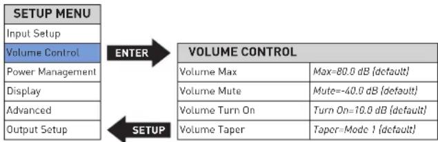
VOLUME CONTROL
flowchart
graph TD
    A["SETUP MENU"] --> B["Input Setup"]
    B --> C["Volume Control"]
    C --> D["Power Management"]
    C --> E["Display"]
    C --> F["Advanced"]
    C --> G["Output Setup"]
    H["VOLUME CONTROL"] --> I["Volume Max"]
    H --> J["Volume Mute"]
    H --> K["Volume Turn On"]
    H --> L["Volume Taper"]
    H --> M["Max=80.0 dB {default}"]
    H --> N["Mute=-40.0 dB {default}"]
    H --> O["Turn On=10.0 dB {default}"]
    H --> P["Taper=Mode 1 {default}"]
Volume Control settings let you customize the performance of the preamp's Volume and Mute functions.
Max Vol: this setting sets the maximum line output volume level in 0.1dB increments between 40.0dB and 80.0dB. The factory default maximum volume is 80.0dB.
Mute: this setting lets you set the amount of line output level attenuation that occurs when the Mute button is engaged, in 0.1dB increments between -10dB and -80.0dB. The factory default mute attenuation is -40dB.
Turn On: this setting lets you set a line output volume level to which your preamp will default every time you turn it on.
o 10.0dB - 60.0dB: choose a turn-on volume level in 0.1dB increments between 10.0db and 60.0db. The factory default setting is 10.0dB.
o Last: the volume level setting from the previous time the unit was powered down is retained.
CAUTION: setting the Turn-On parameter to Last can result in louder-than-expected power-up volume if the preamp was set to a high volume level setting when last powered down.
Taper: this setting lets you choose the desired taper for the volume control, from the following options:
Mode 1: the faster you rotate the volume knob the more quickly the volume will change. Rotating the knob slowly slows the rate the volume changes, allowing you to make very precise adjustments in the listening level. This is the factory default setting.
Mode 2: Similar to Mode 1, with a "faster" response curve, with more gain change for a similar range of knob travel.
Mode 3: When increasing the volume the volume changes quickly through the low volume range, and then decelerates in the higher range, for precision adjustments. When decreasing the volume the control works in the opposite fashion, changing quickly through the high volume range and decelerating in the lower range.
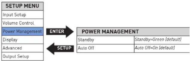
POWER MANAGEMENT AND DISPLAY
flowchart
graph TD
    A["SETUP MENU"] --> B["ENTER"]
    B --> C["POWER MANAGEMENT"]
    C --> D["SETUP"]
    D --> E["Input Setup"]
    D --> F["Volume Control"]
    D --> G["Power Management"]
    D --> H["Display"]
    D --> I["Advanced"]
    D --> J["Output Setup"]
    C --> K["Standby"]
    C --> L["Standby=Green (default)"]
    C --> M["Auto Off"]
    C --> N["Auto Off=On (default)"]
The Power Management and Display parameters let you customize power-related functions.
Standby: this setting lets you set the Standby mode to one of the following options:
Green: this mode removes power from almost all of the circuits, allowing the unit to be activated only via an IR control signal, a 5V - 12V trigger voltage or a press of the Standby button. This mode provides maximum power conservation and is the factory-default Standby mode.
Power Save: this mode removes power from the audio circuits, but keeps the control circuitry powered and ready to receive commands from either the front-panel controls or the remote control. This mode provides moderate power conservation.
Normal: this mode shuts off the display and mutes audio outputs, but keeps all of the control and audio circuits powered. This mode provides the least amount of power conservation but allows the audio circuits to remain warmed up to deliver optimal performance at all times.
Auto Off: this setting lets you engage or disengage the Auto Off function, which puts your preamp into the Standby mode after 20 minutes of inactivity (no audio signal, and no control input).
Display: this menu gives you access to the following display parameters:
Intensity: lets you set the brightness of your preamp's display to High, Med, Low, or Off (which turns the display off entirely until a control is operated). The factory default setting is High.
Timer (only takes effect when the display intensity is set to Off): lets you choose how long the display remains lit after the last time a control is operated. Choose from 10 seconds, 4 seconds, or 2 seconds. The factory default setting is 10 seconds.
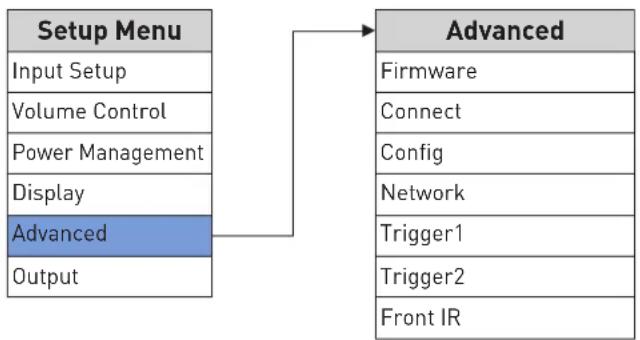
ADVANCED
flowchart
graph TD
    A["Setup Menu"] --> B["Advanced"]
    A --> C["Input Setup"]
    A --> D["Volume Control"]
    A --> E["Power Management"]
    A --> F["Display"]
    A --> G["Advanced"]
    A --> H["Output"]
    B --> I["Firmware"]
    B --> J["Connect"]
    B --> K["Config"]
    B --> L["Network"]
    B --> M["Trigger1"]
    B --> N["Trigger2"]
    B --> O["Front IR"]
The Advanced section of the Setup menu gives you access to a range of configuration and administrative settings and functions.
Firmware: this menu gives you access to the following firmware-related functions:
Version: displays the version number of the currently loaded firmware. (This setting is informational only, and does not provide any adjustments.)
Update: lets you update your preamp's firmware, either from a flash drive inserted in the rear-panel USB Type A port or from a connected computer over the Ethernet connection. (If you press Enter when ENET is selected, the preamp's display shows "Start Download" to remind you to connect via a browser and begin downloading the firmware.) To update via a flash drive:
- Select USB and press Enter.
- The preamp will read the USB drive. The display will show "Check updates..." while the drive is being read
- When the preamp finds a valid firmware file on the drive, the display will show "Updating..."
- If the preamp does not find a valid firmware file on the drive, the display will show "Not Available."
Connect: this menu lets you select the type of control connection you made to your preamp: Ethernet (default), or RS232.
Config: this menu lets you import or export Setup menu configuration settings.
Export: press Enter to export all setup configuration information to a thumb drive inserted in the rear-panel USB Type A port. This data can then be used to identically configure other preamplifiers, or serve as a backup so you can easily reconfigure your preamp.
Import: press Enter to import all setup configuration information from a thumb drive inserted in the rear-panel USB Type A port.
Lock: engage the Lock to prevent accidental changing of Setup menu parameters. The factory default setting is Off.
Restore: lets you restore all parameters to their factory-default condition.
Network: this menu offers access to the following network-related parameters:
Name: N°526XXX or N°523XXX: Displays your preamp's network name (the X's represent the last three digits of the unit's unique MAC address). This setting is informational only and does not provide any user adjustments.
DHCP: lets you toggle DHCP mode (network auto-configuration) on or off. The factory default behavior is On. When the mode is set to Off, you can specify static IP and Subnet addresses for your preamp. Selecting Renew (available only when DHCP is set to On) refreshes your DHCP configuration, assigning a new IP address to your preamp. This function is often useful when troubleshooting a network connection.
Current IP: shows the IP address currently assigned (by DHCP or manually) to your preamp.
Current subnet: shows the subnet address currently assigned (by DHCP or manually) to your preamp.
Current Gateway: shows the gateway address currently assigned (by DHCP or manually) to your preamp.
Manual Entry: this option (only when DHCP is off) allows you to enter a static IP, Subnet, and Gateway address. Holding the Enter button longer than two seconds will start Editing Mode. Use the Select knob to select the character you want to change, use the Volume control to choose from the list of available characters and press the Enter button to confirm each character. After the last character is entered or Enter button has been held longer than two seconds, the new address will be saved.
Trigger: this setting configures how the 12V trigger relay data is sent and received. Most components require this to be set at "Normal," but some products (such as some older Mark Levinson components) require that it be set to Pulsed. There are two triggers available. The menu options allow user to disable trigger and set up the delay time.
Front IR: this menu allows you to turn the unit's front IR receiver on or off. If you have connected the unit's rear-panel IR input to an IR control device, set the Front IR receiver to Off to avoid interference.
OUTPUT
flowchart
graph TD
    A["SETUP MENU"] --> B["Input Setup"]
    A --> C["Volume Control"]
    A --> D["Power Management"]
    A --> E["Display"]
    A --> F["Advanced"]
    A --> G["Output Setup"]
    G --> H["ENTER"]
    H --> I["OUTPUT SETUP"]
    I --> J["XLR Linc Out"]
    I --> K["Mode=Variable (default)"]
    I --> L["RCA Line Out"]
    I --> M["Mode=Variable (default)"]
    I --> N["Headphone"]
    I --> O["Impedance=Low (default)"]
    G --> P["SETUP"]
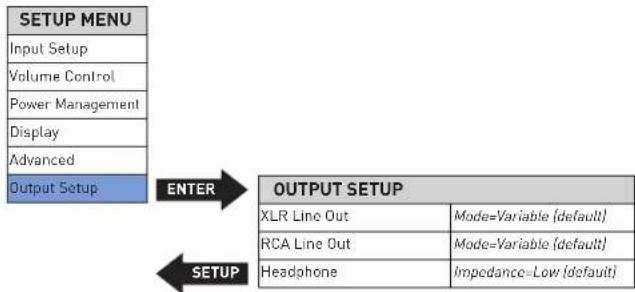
The Output section of the Setup menu lets you configure the outputs.
Line Out: this menu lets you set the Balanced and Single-ended outputs to Fixed, Variable or High Pass Filter:
Fixed: use this setting when you have connected the Balanced or Single-ended outputs to a recording device. The outputs will remain at a fixed level regardless of the volume control level.
Variable: This is the default setting. use this setting when you have connected the Balanced or Single-ended outputs to a powered subwoofer or to an external amplifier. The output level will vary with the level of the volume control.
High Pass: this menu allows you to activate a 24dB-per-octave, 4th-order Butterworth 80Hz high-pass filter on the Balanced or Single-ended outputs. If you have connected a powered subwoofer to one of the outputs and want to restrict the low frequencies sent to your system's main speakers, set the High Pass filter to On for the output connected to your speakers' power amplifier(s). Note: the Headphone output is always full-range and Variable.
Headphone: this menu lets you select Low or High Impedance for the Headphone output. The factory default setting is Low Impedance, which works with all kinds of headphones. Some listeners may prefer the High Impedance setting when using higher impedance headphones. There is no "correct" setting; use what you prefer.
SSP SETUP
In the past, the differing number of channels in each component made integration between two-channel and multichannel components difficult. Sending multichannel processor output signals to a stereo Preamplifier distorts calibrated processor output levels. Multichannel processor volume controls adjust the relative volume level of all channels in unison. However, stereo Preamplifier volume controls adjust the relative volume level of just the front left and right channels, leaving the center, surround, and subwoofer channels unaffected.
To avoid these problems when the preamplifier is connected with an associated surround sound processor, the SSP Mode allows selected input sources to pass through the preamp without interference. When SSP Mode is activated, the preamp's volume control is deactivated to prevent the preamp from distorting channel balance. As a result, the processor controls the relative volume level of all channels while maintaining its calibrated output levels.
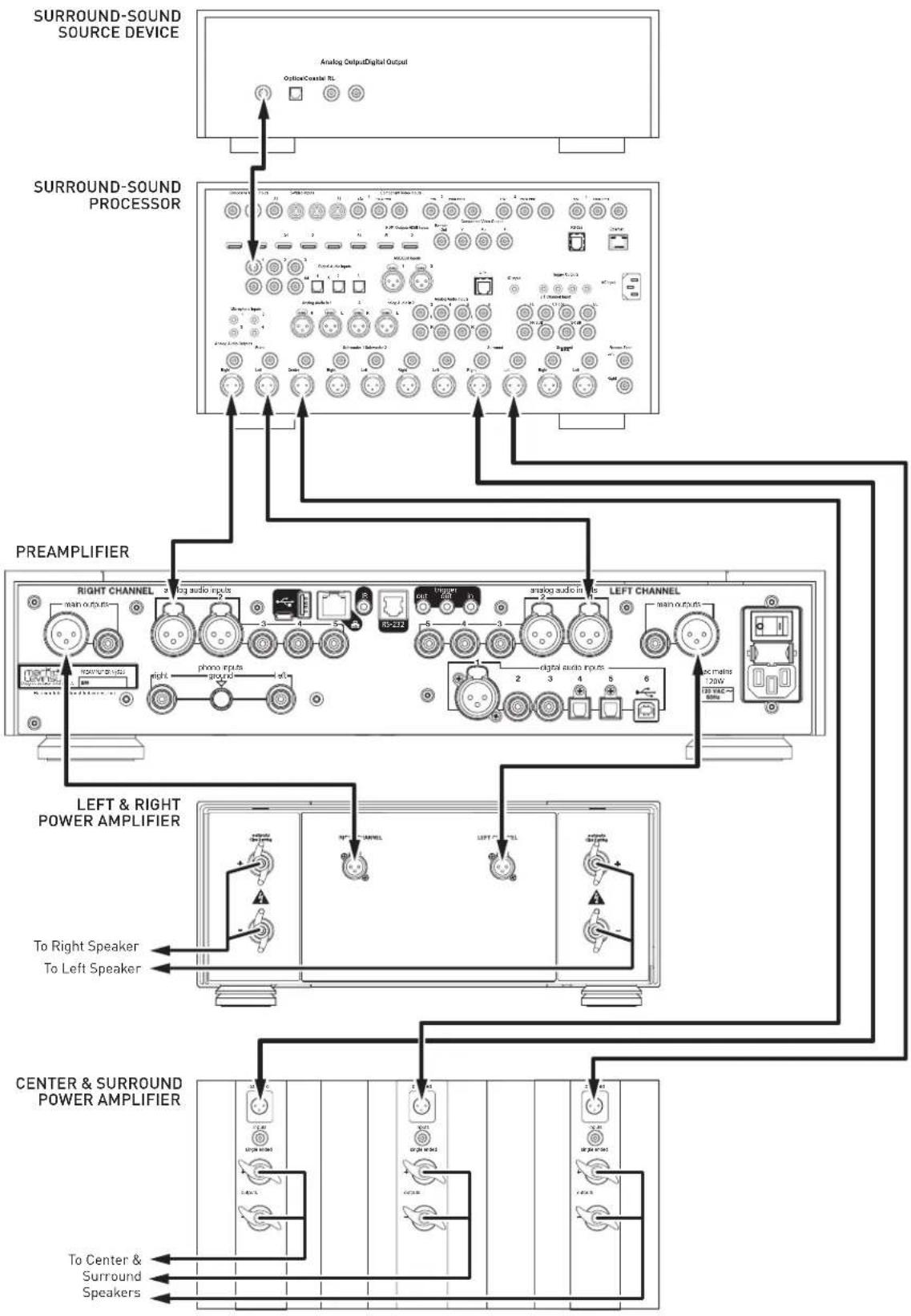
To connect the preamp with a surround sound processor:
- Make sure the preamplifier and all associated components are powered off and disconnected from electrical outlets.
- Connect the output connectors on the surround-sound source component to the input connectors on the surround-sound processor. For example, if the source component is a Blu-ray disc player, connect it to the appropriate input connectors on the surround sound processor.
- Connect the front left and right output connectors on the processor to the desired analog input connectors on the N°526 or N°523 preamplifier. For best performance, use balanced connections whenever possible.
- Connect the center, surround, and subwoofer output connectors on the processor to the appropriate input connectors on the power amplifier(s).
- Connect the preamplifier's outputs to the amplifier(s) connected to the system's left and right (main) speakers.
To activate SSP Mode for a selected input:
CAUTION: Before activating the SSP mode for any input, set the associated surround sound processor volume control to a reasonable level to prevent sending dangerous signal levels to the associated loudspeakers.
- Activate the Setup menu by pressing the Setup button
- Select Input Setup, and press Enter
- Select the analog input you wish to configure for SSP use, and press Enter
- Select SSP, and press Enter
- Set the SSP parameter to On, and press Enter
- Press the Setup button four times to step backward through the menu hierarchy and exit the Setup menu
flowchart
graph TD
    A["SURROUND-SOUND SOURCE DEVICE"] --> B["Analog Output Digital Output"]
    B --> C["Surround-SOUND PROCESSOR"]
    C --> D["PREAMPLIFIER"]
    D --> E["LEFT & RIGHT POWER AMPLIFIER"]
    E --> F["CENTER & SURROUND POWER AMPLIFIER"]
    F --> G["To Center & Surround Speakers"]
    style A fill:#f9f,stroke:#333
    style B fill:#ccf,stroke:#333
    style C fill:#cfc,stroke:#333
    style D fill:#fcc,stroke:#333
    style E fill:#cff,stroke:#333
    style F fill:#ffc,stroke:#333
TROUBLESHOOTING
Incorrect operation is sometimes mistaken for malfunction. If problems occur, see this section for troubleshooting information. If problems persist, contact your authorized Mark Levinson dealer.
NO POWER
Examine the power cord to ensure that it is connected to both the AC mains connector and a working, unswitched electrical outlet.
Make sure the preamp is powered on with the rear-panel Power switch. Examine the electrical circuit breaker to ensure that power is being supplied to the electrical outlet to which the preamp is connected.
Make sure the preamp is not in standby. The front-panel standby LED illuminates fully and continually when the preamplifier is On. The LED flashes slowly when the preamp is in Standby mode.
REMOTE CONTROL DOES NOT OPERATE
Eliminate obstructions between the remote control IR transmitter and the IR receiver on the front-panel display. Make sure the rear-panel IR input connector is not being used.
Make sure the remote control is positioned within 17 feet (5m) of the front panel. If the chassis is placed inside a glass cabinet, tinted glass will reduce the remote control range.
Make sure the remote control signal is being received at the IR receiver on the front-panel display at a reasonable angle.
Make sure the IR receiver on the front-panel display is not exposed to strong sunlight, halogen light, or fluorescent light. This can cause IR reception to become unreliable.
Replace the remote control batteries.
NO SIGNAL AT THE OUTPUTS
Examine all audio cables to ensure a solid connection between the preamplifier and all associated components. Examine the speaker cables to ensure a solid connection between the speakers and the amplifiers. Make sure that the connected speakers are operational. Make sure the volume is set to an audible level.
Make sure the mute is deactivated. Make sure the Offset setting for the selected input is not reducing the volume to an inaudible level. Make sure all associated components are connected to working electrical outlets and powered on. Make sure the source device connected to the preamp's selected input is producing an output signal.
MISSING INPUT
Make sure the Name parameter for the selected input has not been set to Unused in the Setup menu.
DIGITAL AUDIO DROPOUTS
Set PLL Lock to Wide for the digital input exhibiting the dropout problem.
AUDIO HUM
Disconnect components one at a time to isolate the problem.
Once the problem is identified, make sure the problematic component is properly grounded and connected to the same electrical circuit as the preamp.
VOLUME CAN'T BE SET TO MAXIMUM
You have the option of establishing a maximum volume level in the Setup menu. If this option is set, it can prevent the unit's maximum volume level of 80.0 from being reached. Refer to Volume Control / MaxVol for more information.
FRONT-PANEL DISPLAY NOT WORKING
Verify that the Intensity parameter in the Setup menu is not set to Off.
NO NETWORK CONNECTIVITY
Verify that the network cables are properly connected between the router, switch or hub and the preamp.
Verify the age of the router, switch or hub. If the router, switch or hub is more than ten years old, there may be a communication issue with the preamp. Power cycle the preamp and use a newer router, switch or hub between the network and the preamp.
IF ALL ELSE FAILS...
Make sure the display is not turned off by pressing the display button.
Disconnect the AC power cord from the unit. Pull out the fuse drawer and inspect the fuses, making sure the wire inside is not broken and that the glass envelope is not discolored. Replace fuses if necessary.
Power cycle the preamp with the rear-panel Power switch, waiting at least 10 seconds between powering the unit off and on.
Restore factory-default settings (See Advanced: Config / Restore).
Contact your authorized Mark Levinson dealer.
Contact Mark Levinson Customer Service at 888-691-4171 or marklevinson.com.
MARK LEVINSON N° 526 AND N° 523 SPECIFICATIONS
LINE STAGE
Gain
• Normal gain setting
- High gain setting
• Fixed mode, normal gain setting
• Fixed mode, high gain setting
13.5dB balanced; 7.5dB single-ended
19.5dB balanced; 13.5dB single-ended
3.0dB balanced; -3.0dB single-ended
9.0dB balanced; 3.0dB single-ended
Frequency response
- 20Hz to 20kHz
- 0.4Hz to 370kHz
±0.02dB
+0.1 / -3dB
Total harmonic distortion plus noise (THD+N)
- at 1kHz (2V RMS single-ended or 4VRMS balanced output)
- at 20kHz (2V RMS single-ended or 4V_RMS balanced output)
<0.003%
<0.005%
Signal-to-noise ratio
• 20Hz to 20kHz, wideband, unweighted
- A-weighted
- Reference to 2V RMS single-ended or 4M _MS balanced output, max volume
97dB
100dB
115dB @ 1kHz
105dB @ 20kHz (spot noise)
Crosstalk
- at 1kHz
- at 20kHz
Channel separation
High-pass filter
Volume control
<-107dB
<-82dB
below noise floor (>115dB @ 1kHz)
defeatable 80Hz, 4^th order (24dB/octave) Butterworth
balanced, current mode, discrete 15-bit R-2R ladder
SINGLE-ENDED (RCA) INPUTS
- Input impedance >45kΩ
• Maximum input level normal gain setting: >10V
RMS, high gain setting: >7VRMS
BALANCED (XLR) INPUTS
- Input impedance >45kΩ
• Maximum input level normal gain setting: >15V
RMS, high gain setting: >7.5V RMS
SINGLE-ENDED (RCA) OUTPUTS
• Output impedance <80Ω
• Maximum output level >11V
RMS
BALANCED (XLR) OUTPUTS
• Output impedance <160Ω
• Maximum output level >22V
RMS
HEADPHONE OUTPUT
| Output impedance | selectable; <3Ω or 75Ω |
| Maximum output, low impedance setting | |
| 30Ω (0.3W), 20Hz to 20kHz, <0.1% THD | >3VRMS |
| 300Ω, 20Hz to 20kHz, <0.1% THD | >9VRMS |
| Maximum output, high impedance setting | |
| 300Ω, 20Hz to 20kHz, <0.1% THD | >7VRMS |
| Total harmonic distortion plus noise (THD+N) | |
| 20Hz to 20kHz, 2V RMS at 30Ω | <0.03% |
| 20Hz to 20kHz, 2V RMS at 300Ω | <0.01% |
PHONO STAGE
| • RIAA frequency response• Infrasonic filter | 20Hz to 20kHz, ±0.3dBdefeatable, 15Hz, 2^nd order (12dB/octave) |
| Moving Magnet mode• Input resistance• Input capacitance• Gain• Total harmonic distortion plus noise• Signal-to-noise ratio (Referred to 2V RMS output) | 47kΩselectable; 50, 100, 150, 200, or 680pF40dB @ 1kHz<0.03%, 20Hz to 20kHz, 2V_RMS output>97dB (20Hz to 20kHz, wideband, unweighted)>102dB (A-weighted)>110dB @ 20Hz to 20kHz (spot noise)>95mV @ 1kHz; >285mV @ 20kHz |
| • Maximum input level | |
| Moving Coil mode• Input resistance• Input capacitance• Gain• Total harmonic distortion plus noise | selectable; 20, 33, 50, 66, 100, 200, 330, 500, 1000, or 47kΩ50pFselectable; 50, 60, or 70dB @ 1kHz50dB gain setting: <0.02%, 20Hz to 20kHz, 2V_RMS output60dB gain setting: <0.02%, 20Hz to 20kHz, 2V_RMS output70dB gain setting: <0.04%, 20Hz to 20kHz, 2V_RMS output |
| • Signal-to-noise ratio (Referred to 2V RMS output) | 50dB gain setting: >87dB (20Hz to 20kHz, wideband, unweighted)50dB gain setting: >94dB (A-weighted)50dB gain setting: >100dB at 20Hz to 20kHz (spot noise)60dB gain setting: >77dB (20Hz to 20kHz, wideband, unweighted)60dB gain setting: >84dB (A-weighted)60dB gain setting: >90dB at 20Hz to 20kHz (spot noise)70dB gain setting: >68dB (20Hz to 20kHz, wideband, unweighted)70dB gain setting: >74dB (A-weighted)70dB gain setting: >80dB at 20Hz to 20kHz (spot noise) |
| • Maximum input level | 50dB gain setting: >30mV @ 1kHz; >105mV @ 20kHz60dB gain setting: >9.5mV @ 1kHz; >90mV @ 20kHz70dB gain setting: >3.2mV @ 1kHz; >30mV @ 20kHz |
DIGITAL-TO-ANALOG CONVERTER (№526 ONLY)
| Output voltageFrequency responseTotal harmonic distortionSignal-to-noise ratio (Referred to 3.7VRMS/0dBFS output)Sample rates/bit depthPCMDSD | 3.7V_RMS @ full scale (0dBFS)20Hz to 20kHz, +0 / -0.2dB<0.0001% @ 1kHz, full scale (0dBFS)<0.0003% @ 20kHz, full scale (0dBFS)>117dB (20Hz to 20 kHz, wideband, unweighted)>120dB (A-weighted) |
| 32, 44.1, 48, 88.2, 96, 176.4, or 192kHz; up to 32 bitsNative or DoP (DSD over PCM), single- and double-speed (2.8 and |
GENERAL
- Analog audio connectors
Line inputs
Phono input
Outputs
• Digital audio input connectors (N 9526 only)
Balanced
Coaxial
Optical
USB asynchronous
- Control connectors
RS-232
Infrared (IR)
DC triggers
Ethernet
USB
- Mains voltage
• Power consumption
Standby, Green mode
Standby, Power Save mode
Standby, Normal mode
Power on, idle
Power on, idle, headphones connected
- Dimensions
Unit
With Packaging
3 pairs single-ended (RCA), 2 pairs balanced (XLR)
1 pair single-ended phono inputs (RCA), 1 phono ground binding post
1 pair single-ended line (RCA), 1 pair balanced line (XLR), 1 TS 14
(6.3mm) headphone
1 AES/EBU (XLR)
2 S/PDIF (RCA)
2 Toslink
1 USB Type B)
1 RJ-12
1 18 " (3.5mm) phone jack
2 programmable 12V outputs ( 18 " / 3.5mm phone jack), 100mA maximum
1 programmable 12V input ( 18 " / 3.5mm phone jack)
1 RJ-45
1 USB Type A, 1 Micro USB
100VAC, 115VAC, or 230VAC, factory set
0.4W
5W
Height: 3.97" [101mm]
Height without feet: 3.45" (88mm)
Width: 17.25"/438mm
Depth: 19.10" (485mm)
Weight: 41 lbs. (18.6kg)
Height: 17" (432mm)
Width: 26" (660mm)
Depth: 26" (660mm)
Weight: 60 lbs. (27.2kg)

HARMAN International Industries, Incorporated
8500 Balboa Boulevard
Northridge, CA 91329 USA
© 2016 HARMAN International Industries, Incorporated. All rights reserved.
Mark Levinson and Clari-Fi are registered trademarks of HARMAN International Industries, Incorporated. Blu-ray is a trademark of the Blu-ray Disc Association. SACD (Super Audio CD) is a trademark of Sony Corporation. Other company and product names may be trademarks of the respective companies with which they are associated.
This document should not be construed as a commitment on the part of HARMAN International Industries, Incorporated. The information it contains, as well as the features, specifications and appearance of the product, is subject to change without notice. HARMAN International Industries, Incorporated, assumes no responsibility for errors that may appear within this document.
For customer service and product shipment information, refer to our website: marklevinson.com
Part No. 070-90027 Rev: 2.0

PHONO INPUT SETTINGS (A6)
| Setup Name | Ver opciones de definición de nombres |
| Setup Offset | Offset=0.0 dB (predeterminado) |
| Setup Phono Type | Ph Type=MM (predeterminado) |
| Setup Ph Gain | Solo tipo MC |
| Setup Ph Balance | Balance= 0.0 dB (predeterminado) |
| Setup Infra Filt | Infra Filt-Off (predeterminado) |
| Setup R Load | Solo tipo MC |
| Setup C Load | Solo tipo MM |
| DIGITAL INPUT SETTINGS (D1-D6) | |
| Setup Name | Ver opciones de definición de nombres |
| Setup Offset | Offset=0.0 dB (predeterminado) |
| Setup Clari-Fi | Clari-Fi=Off (predeterminado) |
| Setup PCM Filter | Filter=Fast (predeterminado) |
| Setup PLL Lock | PLL Lock=Normal (predeterminado para D1-D5 solamente) |
| Setup DSD Filter | Filter=47k (predeterminado para USB [D6] solamente) |
HARMAN International Industries, Incorporated
8500 Balboa Boulevard
Northridge, CA 91329 Estados Unidos
© 2016 HARMAN International Industries, Incorporated. Todos los derechos reservados.
HARMAN International Industries, Incorporated
8500 Balboa Boulevard
Northridge, CA 91329 USA
© HARMAN International Industries, Incorporated, 2016. Tous droits réservés.
flowchart
graph TD
    A["SETUP MENU"] --> B["Input Setup"]
    A --> C["Volume Control"]
    A --> D["Power Management"]
    A --> E["Display"]
    A --> F["Advanced"]
    A --> G["Output Setup"]
    G --> H["ENTER"]
    H --> I["OUTPUT SETUP"]
    I --> J["XLR Line Out"]
    I --> K["RCA Line Out"]
    I --> L["Headphone"]
    I --> M["Impedance=Low (认)"]
    I --> N["Mode=Variable (认)"]
HARMAN International Industries, Incorporated
8500 Balboa Boulevard
Northridge, CA 91329 USA
© 2016 HARMAN International Industries, Incorporated. 保留所有权利。
HARMAN International Industries, Incorporated
8500 Balboa Boulevard
Northridge, CA 91329 USA
© 2016 HARMAN International Industries, Incorporated. 無断複写·複製·転載禁止。