D — Cooker — Mode d'emploi PDF")
KP 648 MS.B (X)D - Cooker INDESIT - Free user manual and instructions
Find the device manual for free KP 648 MS.B (X)D INDESIT in PDF.

User questions about KP 648 MS.B (X)D INDESIT
0 question about this device. Answer the ones you know or ask your own.
Ask a new question about this device
Download the instructions for your Cooker in PDF format for free! Find your manual KP 648 MS.B (X)D - INDESIT and take your electronic device back in hand. On this page are published all the documents necessary for the use of your device. KP 648 MS.B (X)D by INDESIT.
USER MANUAL KP 648 MS.B (X)D INDESIT
Instructions for use and installation
Cuisinières electrogaz
IE GB Electric-gas cooker Instructions for use and installation
Congratulations on choosing an Indesit appliance, which you will find is dependable and easy to use. We recommend that you read this manual for best performance and to extend the life of your appliance. Thank you.
SAFETY PRECAUTIONS
THESE INSTRUCTIONS ARE ONLY VALID FOR THE COUNTRIES OF DESTINATION WHOSE SYMBOLS ARE SHOWN IN THE BOOKLET AND THE APPLIANCE RATING PLATE.
- This appliance has been designed for private, nonprofessional use in normal dwellings.
- Read the recommendations in this instruction booklet carefully, as they give important advice regarding safe installation, use and maintenance. Keep this booklet in a safe place for further reference when required.
- Oven accessories which may come into contact with food are made of materials which comply with the contents of EEC Regulation 89/109 of 21.12.88 and national regulations in force.
- After having removed the packaging, check that the appliance is intact. If in doubt, do not use the appliance and contact professionally qualified personnel.
- Some parts are covered with a removable scratchproof film. Before using the appliance the film should be removed and the underlying part cleaned with a cloth and a non-abrasive household cleaning product. When switching on for the first time, it is advisable to heat the empty oven at maximum temperature for about 30 minutes to eliminate any residue from manufacture.
- All installation and adjustment operations should be carried out by qualified technicians in accordance with current regulations. Specific indications are given in the "instructions for the installer" paragraph.
- Before connecting the appliance, make sure that the data on the rating plate (situated on the rear part of the appliance and on the last page of the instruction booklet) correspond to those of the mains electricity and gas supplies.
-
During operation, the oven glass door and adjacent parts of the appliance become hot. Make sure, therefore, that children do not touch the appliance. For greater safety, an additional child-safety device is available from our Head Office and our Authorised Service Centres (see enclosed list). When ordering this, please give the code: BAB - followed by the appliance model. The model is stamped on the plate which is visible on the front part of the oven upon opening the door.
-
Check that the capacity of the electrical system and the power outlets are suitable for the maximum power of the appliance, indicated on the rating plate. If in doubt, consult a professionally qualified technician.
- Periodically check the condition of the gas connection pipe and have it replaced by a qualified technician as soon as it shows any signs of wear or anomaly.
- Under no circumstances should the user replace the power supply cable or the gas connection pipe of this appliance. In the event of damage or the necessity for replacement, only contact an authorised service centre.
- Do not leave the appliance plugged in if it is not in use. Switch off the main switch and gas supply when you are not using the cooker.
- The burners and the cast-iron pan supports remain hot for a long time after use. Take care not to touch them.
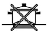
- To avoid accidental spillage do not use cookware with uneven or deformed bottoms on the burners.
- Never use flammable liquids such as alcohol or gasoline, etc. near the appliance when it is in use.
- Do not use steam cleaners to clean your oven
- To obtain the best results with the cooktop, several fundamental rules should be followed while cooking or preparing food. Use cookware with a flat bottom to make certain that the pot sets properly on the cooking area.
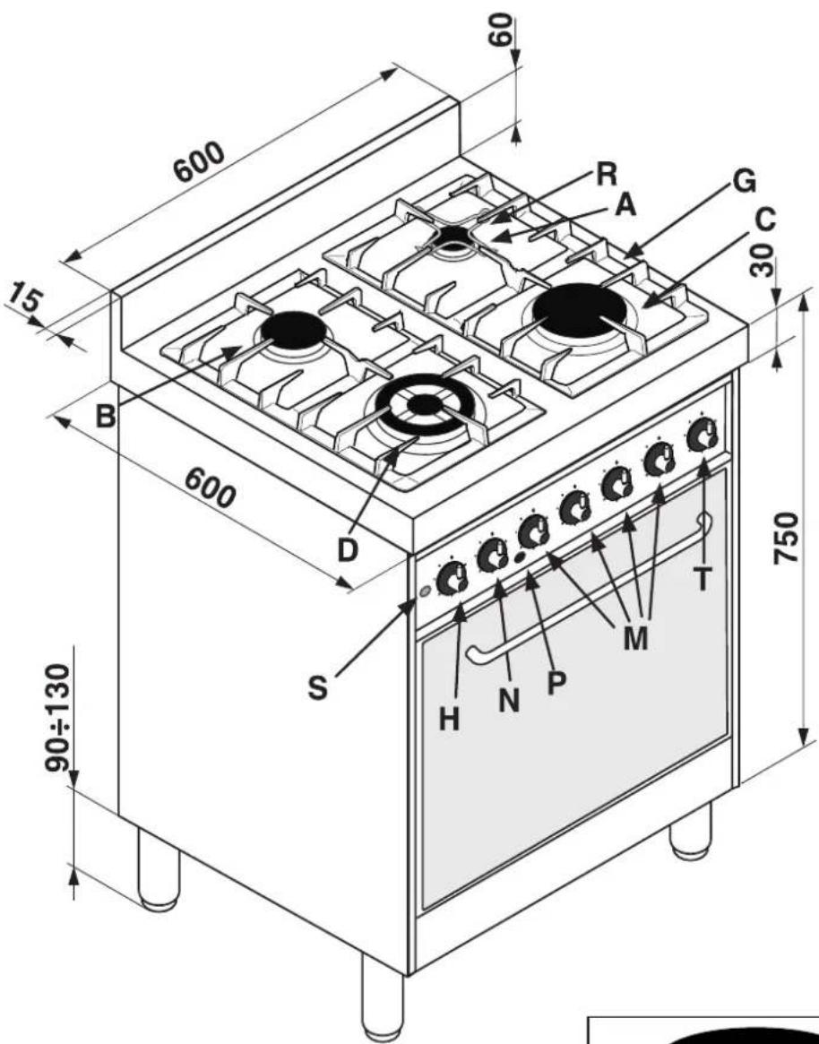
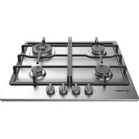
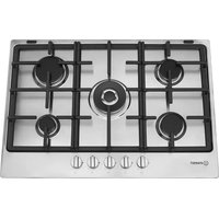
A Auxiliary gas burner
B Semi-rapid gas burner
C Rapid gas burner
D Triple ring gas burner
G Support Grid for Cookware
R Reduction Grid for Cookware
M Control Knobs for Gas Burners
P Ignition Pushbutton for gas burners
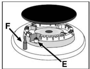
E Ignitor for Gas Burners
F Safety Device - Activates if the flame accidentally goes out (spills, drafts, etc.), interrupting the delivery of gas to the burner.
T Timer
S Electric oven operation indicator light
H Electric oven selector knob (cooking function selection)
N Electric oven thermostat knob (temperature selection)
INSTRUCTIONS FOR USE
HOB OPERATION
The burners are fitted with automatic ignition and a thermocouple safety device, which automatically cuts off the gas from the burner in a few seconds if the flame accidentally goes out during operation.
The burners differ in size and power. Choose the most appropriate one for the diameter of the cookware being used.
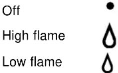
Each burner can be regulated with the corresponding control knob "M" by using one of the following settings:
The symbols near the knobs show the position of the relative burner on the hob.
Toignite a burner, proceed as follows:
- turn the relative knob counter-clockwise until the pointer is on the high-flame symbol;
- press the knob down fully and activate the automatic gas ignition by pushing at the same time the button "P" marked with the symbol
- keep the knob pressed down for about 10 seconds with the flame lit to allow the safety thermocouple to be heated;
- release the knob, checking that the flame is stable. If it is not, repeat the operation.
For minimum power, turn the knob towards the low flame symbol. Intermediate positions are possible by simply putting the knob anywhere between the high and the low flame symbol.
To turn off the burner, turn the knob clockwise to the off position "●".
Important:
- Do not activate the automatic ignition device for more than 15 consecutive seconds.
- Difficulty in ignition is sometimes due to air inside the gas duct.
- If a burner flame accidentally goes out, the gas continues to exit for a few moments before the safety device activates. Turn the control knob to the off position and do not attempt ignition again for at least 1 minute, thereby letting the gas disperse, which could otherwise be a danger.
- When the appliance is not in operation, check that the knobs are in the off position "●". The main gas supply cut-off cock should also be closed.
Using the burners:
To obtain maximum efficiency from the burners, it is advisable to only use pans with a diameter suitable for the burner being used, so that the flame does not extend beyond the pan base (see following table). When a liquid starts boiling, it is advisable to turn the flame down just enough to keep the liquid simmering.
| Burner | Diameter of the pan in cm. |
| Auxiliary A | from 6 to 14 |
| Semi-rapid B | from 15 to 20 |
| Rapid C | from 21 to 30 |
| Triple ring D | from 24 to 30 |
The hob is fitted with a pan reducing support (fig.1), which should only be used on the auxiliary burner "A"
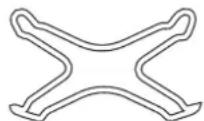
fig.1
OVEN USE (MOD. KP 648 VS - X)
By turning the selector knob "H" marked with the symbol (fig. on page 3), different cooking modes are obtained, as shown in the following table:
| 0 | Off | - |
| 1)Oven light+fan | 50 W | |
| 2)Round heating element+ fan | 2100 W | |
| 3)Grill heating element | 1500 W |
After having selected the heat source, put the thermostat knob "N" (marked with the symbol ) onto the temperature required.
- With this (fan assisted) mode heat is transmitted to the food through pre-heated air made to circulate inside the oven by a fan. The oven heats up very quickly so the food to be cooked may be put into the oven as soon as it is switched on. Cooking is also possible simultaneously on two shelves.
The "fast defrosting" function uses no heating elements, just the oven light and the fan. - Grill operation: a high heat output is used for grilling, so that the surface of the food is immediately browned; this is particularly indicated for meats which should remain tender on the inside.
To grill, turn the selector knob "H" to one of these positions: (grill).
During grilling, do not set the thermostat knob to above 200^ and keep the oven door closed.
MULTI-FUNCTION OVEN (MOD.KP 648 MS -X)
The oven offers nine combinations of heating elements; so the most suitable combination may therefore be chosen for each dish, with convincing results.
By turning the selector knob "H" marked with the symbol , different cooking modes are obtained, as shown in the following table:
| 0 | ffO)0 | |
| 1) Top + Bottom heating s | 0 W | |
| 2) Bottom heating element | 1250 W | |
| 3) Top heating element | 750 W | |
| 4) Grill heating element | 1500 W | |
| 5) Maxigrill (Top + Grill heating elements) | 2250 W | |
| 6) Maxigrill (Top + Grill heating elements) + fan | 2300 W | |
| 7) Bottom heating element + Fan | 1300 W | |
| 8) Rear round heating element + Fan | 2050 W | |
| 9) Fast defrosting | 50 W |
After having selected the heat source, put the thermostat knob "N" (marked with the symbol onto the temperature required.
- For traditional cooking (roasts, biscuits, etc.) in conventional mode use the mode (hot above + below).
Only put the food to be cooked into the oven when it has reached the selected temperature and preferably use just one shelf for cooking.
To provide heat only to the bottom or the top part of the dishes, turn the selector to the position (hot below)
or (hot below + fan) or (hot above);
-
With this (fan assisted) mode heat is transmitted to the food through pre-heated air made to circulate inside the oven by a fan. The oven heats up very quickly so the food to be cooked may be put into the oven as soon as it is switched on. Cooking is also possible simultaneously on two shelves.
-
The "fast defrosting" function uses no heating elements, just the oven light and the fan.
-
Grill operation: a high heat output is used for grilling, so that the surface of the food is immediately browned; this is particularly indicated for meats which should remain tender on the inside.
To grill, turn the selector knob "H" to one of these positions:
(grill), (maxigrill), 中 (maxigrill + fan)
During grilling, do not set the thermostat knob to above 200^ and keep the oven door closed.
Oven light
The oven light comes on automatically when the selector knob is turned to any of its positions.
Indicator light "S"
It indicates that the oven is heating up. When the light goes out, the required temperature has been reached inside the oven.
When the light alternately comes on and goes out, it means that the thermostat is working properly to maintain the oven temperature.
Timer "T"
Manual mode
Turn the timer knob counterclockwise until the pointer is on the symbol manual).
Switch on the oven by turning the selector knob and set the required temperature by turning the thermostat knob.
To switch off the oven, put the timer knob back to its original position "●".
Programmed cooking times mode
Turn the timer knob clockwise, positioning the pointer on the required time (from 10 to 120 minutes).
Switch on the oven by turning the selector knob and set the required temperature by turning the thermostat knob.
At the end of the set time a buzzer sounds and the oven is turned off.
Upon completion of cooking, turn the knobs back to their original position "●".
CLEANING AND MAINTENANCE
To ensure a long life cycle for the appliance, it is essential to carry out a thorough general clean frequently, taking into account that:
- The appliance should be disconnected from the mains supply before starting cleaning operations.
- Avoid cleaning appliance parts when they are still warm.
- The enamelled, chromed or glass parts must be washed with warm water without using abrasive powders or corrosive substances which could ruin them.
- The inside of the oven should be cleaned every time it is used with hot water and detergent; rinse and dry thoroughly.
- The steel parts and especially the areas with the screen-printed symbols should not be cleaned with diluents or abrasive detergents. It is advisable to use only a damp cloth with tepid water and washing up liquid. After cleaning, the surfaces should be rinsed thoroughly with water and then dried well.
- Avoid leaving acidity liquids (vinegar, lemon juice, aggressive detergents, etc.) on enamelled or varnished parts.
- The removable parts of the burners on the hob should be washed frequently with warm water and soap, making sure to remove any caked-on substances. Check that the gas outlet slits are not clogged. Dry the burners carefully before using them again.
- Clean the end part of the automatic glow plug ignitors of the hob frequently.
Greasing the taps
As time passes, a tap may lock or become difficult to turn. In this case it will be necessary to clean inside and replace the grease. This procedure must be performed by a technician authorized by the manufacturer.
Changing the oven lightbulb
Make sure that the appliance is disconnected from the electricity supply.
Unscrew the glass protective cover from inside the oven, unscrew the lightbulb and replace it with an identical one suitable for high temperatures (300^) and with the following characteristics:
Voltage 230 V
Wattage 15 W
- Type E 14.
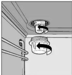
fig.2
COOKING TIPS
Cooking times may change according to the nature of the foods, their homogeneity and their volume. When cooking a certain food for the first time, it is advisable to choose the lowest values in the cooking time range given in the table and then increase them if necessary.
CONVENTIONAL OVEN COOKING
| hsidfoepyT °C | erutarepmET emtgnikooC )setunim( | hsidfoepy °C | erutarepmET emtgnikooC )soh( |
| Pastries and cakes | aem | ||
| eipir | 130 | 07-06 | gk84kT 160 |
| seugm | 130 | 04-03 | gk56ooG 160 |
| ekacegnsp | 150 | 03-02 | gk64D 170 |
| ekaclegn | 160 | 05-04 | gk3-12paC 170 |
| ekacaedam | 160 | 05-04 | Braised beef (1-1½ kg.) 160 |
| ekacetalocohC | 170 | 04-03 | Leg of lamb 160 |
| faolteetaf | 170 | 05-04 | Roast hare (2 kg.) 160 |
| fu | 200 | 02-51 | Roast pheasant 160 |
| stcsibysat | 200F | 02-51 | Chicken (1-1½ kg.) 170 |
| Mille feuilles | 200 | 02-51 | |
| tsapsh | 200 | 02-51 | Fish 200 |
| 15-25 minutes |
GRILLING
| Type of dish | Cooking time (minutes) | Position of shelf |
| Chops (0.5 kg.) | 60 | 3rd guide rail |
| Sausages | 15 | 2nd guide rail |
| Grilled chicken (1 kg) | 60 | 1st guide rail |
| Veal on the spit (0.6 kg.) | 60 | - |
| Chicken on the spit (1 kg.) | 60 | - |
The 1^st guide rail is understood as being the lowest position.
FAN ASSISTED COOKING
| Type of dish | Guide rail No. from bottom | Quantity kg. | Temperature °C | Time (minutes) |
| Pastries and cakes* With beaten mix, in mould* With beaten mix, without mouldShort pastry, flan baseShort pastry with wet fillingShort pastry with dry filling* With natural leavened mixSmall pastries and cakes | 1-31-3-41-3-41-3-41-3-41-3-41-3-41-3-4 | 110.51.51175117511751175 | 175175175175175160 | 60503070455030 |
| Meat Roasts under grillVealBeef English roast beefPorkChicken Roasts on trayVealBeefPorkChicken Turkey slicesDuck CasserolesBraised beefBraised veal | 222222221-31-31-31-31-31-31-31-3 | 11180180220180200160160160180180180175 | 180180180180180180180 | 6070507080909090120120 |
| Fish Fillets, steaks, cod hake, soleMackerel, turbot, salmonOysters | 1-31.31-3 | 1180180180 | 160160160160180180 | 8090909090120120 |
| TimbalesBaked pasta dishVegetable pudding* Sweet and savoury soufflés* Pizzas and savoury rollToasted sandwiches | 1-31-31-31-31-3 | 22185185180200190 | 185185180180200190 | 605050503015 |
| Defrosting Ready-to-eat dishesMeatMeatMeat | 1-31-31-31-3 | 10.50.751 | 200505050 | 455070110 |
Notes:
1) Cooking times do not include oven pre-heating, except for those marked with an asterisk
2) The indication given in the table for the guide rails is the one that should preferably be used in the event of cooking on more than one level.
3) The indicated times refer to cooking on one shelf only; for cooking on more than one level, increase the time by 5 ÷ 10 min.
4) For roast beef, veal, pork and turkey, on the bone or rolled, increase the times by 20 min.
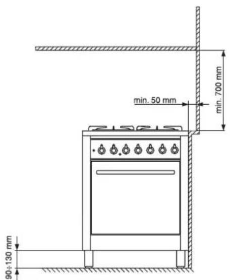
fig.3
The following instructions are provided for qualified installers so that they may accomplish installation, adjustment and technical maintenance operations correctly and in compliance with current regulations and standards. Important: the appliance should be disconnected from the mains electricity supply before any adjustment, maintenance, etc. is carried out. Maximum caution should be used should it be necessary to keep the appliance connected to the electricity supply.
The cookers have the following technical specifications:
Category: II 2H3+ Class: 1
For trouble-free operation of appliances installed in housing units, the minimum distances shown in fig.3 should be observed. Adjacent surfaces and the wall at the rear should also be able to withstand an overheating temperature of 65^ .
Prior to installing the cooker, 90 ÷ 130 mm high supporting feet (provided) should be fitted into the holes to be found in the bottom of the cooker (fig.4). These feet are screw-adjustable and whenever necessary should be used to make sure the cooker stands level.
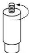
fig.4
Positioning
This appliance may only be installed and operated in permanently ventilated rooms in compliance with current standards. The following requirements must be observed:
- The appliance must discharge combustion products into a special hood, which must be connected to a chimney, flue pipe or directly to the outside (fig.5).
- If it is impossible to fit a hood, the use of an electric fan is permitted, either installed on a window or on an external wall, which must be switched on at the same time as the appliance.
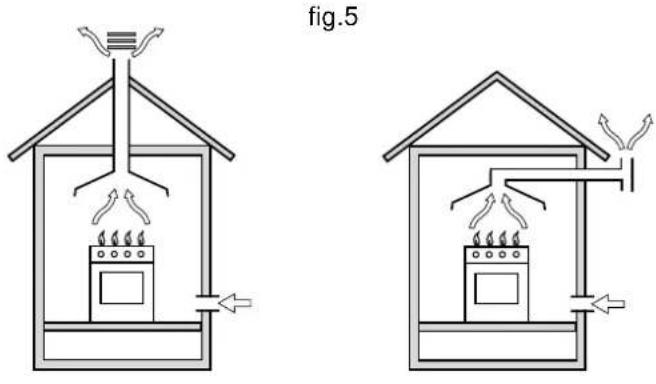
In a chimney stack or branched flue Directly to the outside (exclusively for cooking appliances)
Kitchen ventilation
The air flow into the room where the appliance is installed must equal the quantity of air that is required for regular combustion of the gas and for ventilating the same room. Air must be taken in naturally through permanent apertures made in the outside walls of the room or through single or branching collective ventilation ducts in compliance with current standards and regulations. The air must be taken directly from the outside, from an area far from sources of pollution.
The ventilation aperture must have the following characteristics (fig.6A):
- total free cross section of passage of at least 6cm^2 for every kW of rated heating capacity of the appliance, with a minimum of 100cm^2 (the heating capacity is indicated on the rating plate);
- it must be made in such a way that the aperture, both on the inside and outside of the wall, cannot be obstructed;
- it must be protected, e.g. with grates, wire mesh, etc. in such a way that the above-mentioned free section is not reduced:
- it must be situated as near to floor level as possible.

Detail A Adjacent Room to be
room ventilated
Examples of ventilation holes Enlarging the ventilation slot for comburant air between window and floor
fig. 6A fig. 6B
The air inflow may also be obtained from an adjoining room, provided the latter is not a bedroom or a room where there is a risk of fire, such as warehouses, garages, fuel stores, etc. and is ventilated in compliance with the current standards and regulations. Air from the adjoining room to the one to be ventilated may be made to pass freely through permanent apertures with a cross section at least equal to that indicated above. These apertures may also be obtained by increasing the gap between the door and the floor (fig.6B).
If an electric fan is used for extracting the combustion products, the ventilation aperture must be increased in relation to its maximum performance. The electric fan should have a sufficient capacity to guarantee an hourly exchange of air equal to 3 ÷ 5 times the volume of the kitchen. Prolonged, intensive use of the appliance may require extra ventilation, e.g. an open window or a more efficient ventilation system by increasing the extraction power of the electric fan if installed. Liquid petroleum gas descends towards the floor as it is heavier than air. Apertures in the outside walls in rooms containing LPG cylinders should therefore be at floor level, in order to allow any gas from leaks to be expelled. Do not store LPG cylinders (even when empty) in basements/rooms below ground level; it is advisable to keep only the cylinder in use in the room and connected far from heat sources which could raise its temperature to above 50^ .
Gas supply connection
- Check that the appliance is set for the type of gas available and then connect it to the mains gas piping or the gas cylinder in compliance with current regulations and standards.
- This appliance is designed and set to work with the gas indicated on the label situated on the actual hob. If the gas supply is different from the type for which the appliance has been set, proceed with replacing the corresponding nozzles (provided), following the instructions given in the paragraph "Adaptation to different types of gas".
- For trouble-free operation, suitable use of energy and longer life of the appliance, make sure that the supply pressure complies with the values indicated in table 1 "burner and nozzle specifications", otherwise install a special pressure regulator on the supply pipe in compliance with current standards and regulations.
- Connect in such a way that the appliance is subjected to no strain whatsoever.
Either a rigid metal pipe with fittings must be used for connecting to the threaded cylindrical 1/2''G male flexible fitting situated in the rear right-side of the appliance (fig.7), or a flexible steel tube which must not exceed 2000~mm in length. Connection must be made in compliance with the regulations in force.
Should it be necessary to rotate the fitting, definitely replace the gasket (provided with the appliance).
When the installation has been completed, check the pipe fittings for leaks using a soapy solution (never use a flame). Check that the connecting pipe cannot come into contact with moving parts which could damage or crush it. Check that the natural gas supply is sufficient for the appliance when all the burners are in use.
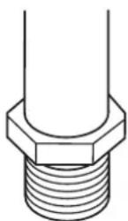
fig.7
Important: A pressure regulator, in compliance with the standards in force, must be inserted when connecting to a liquid gas supply (in a cylinder).
Adapting the cooker to a different type of gas
If the appliance is to be converted for use with a type of gas different from the one for which it was set in the factory (indicated on the label to be found on the hob), the burner nozzles should be replaced as follows:
- remove the grids and the burners.
- unscrew the nozzles "A" (fig.8), using a 7 mm socket spanner and replace them according to the table 1 "burners and nozzles specifications" with ones which are suitable for the new type of gas.
- re-assemble all the components.
- on completing the operation, replace the old rating label with the one showing the new type of gas; the sticker is available from our Service Centres.
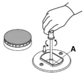
fig.8
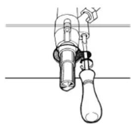
fig.9
Adjusting the low flame
- Put the tap to the low flame position (the burner should be lit);
- Remove the tap knob and turn the adjusting screw, situated to the side of the tap stem (fig. 9) until the flame is small yet steady, using a screwdriver (loosening the screw increases the height of the flame, tightening it decreases it).
N.B.: the adjusting screw must be fully screwed in for liquid gas.
- having obtained the low flame setting required and with the burner lit, abruptly change the position of the knob several times from minimum to maximum and vice versa and check that the flame does not go out.
- Refit the tap knobs.
BURNER AND NOZZLE SPECIFICATIONS
| Table 1 | Liquid gas | Natural gas | |||||||
| Burner | Diameter (mm) | Thermal power kW (H.s.*) | By-pass 1/100 | Nozzle 1/100 | Flow * g/h | Nozzle 1/100 | Flow* l/h | ||
| Nomin. | Reduc. | (mm) | (mm) | G30 | G31 | (mm) | G20 | ||
| Rapid C | 100 | 3.00 | 0.7 | 40 | 86 | 218 | 214 | 116 | 286 |
| Semi-rapid B | 75 | 1.65 | 0.4 | 30 | 64 | 120 | 118 | 96 | 157 |
| Auxiliary A | 55 | 1.00 | 0.3 | 27 | 50 | 73 | 71 | 71 | 95 |
| Triple ring D | 130 | 3.25 | 1.3 | 57 | 91 | 236 | 232 | 124 | 309 |
| Supply pressure | 30 | 37 | 20 | ||||||
TECHNICAL SPECIFICATIONS
ENERGY LABEL
Directive 2002/40/EC on the label of electric ovens Norm EN 50304
Energy consumption for Natural convection
heating mode: Convection (only for mod. KP 688 MS) Declared energy consumption for Forced convection Class
heating mode: Fan assisted
- At 15^ and 1013 mbar-dry gas
Propane G31 H.s. = 50,37 MJ/kg
Butane G30 H.s. = 49,47 MJ/kg
Methane G20 H.s. = 37,78 MJ/m

3
This appliance conforms to the following European Economic Community directives:
- 73/23/EEC of 19/02/73 (Low Voltage) and subsequent modifications;
- 89/336/EEC of 03/05/89 (Electromagnetic Compatibility) and subsequent modifications;
- 90/396/EEC of 29/06/90 (Gas) and subsequent modifications;
- 93/68/EEC of 22/07/93 and subsequent modifications.
ELECTRICAL CONNECTION
THE APPLIANCE MUST BE EARTHED
The appliance is designed to work with alternating current at the supply voltage and frequency indicated on the rating plate (situated on the rear part of the appliance and on the last page of the instruction manual). Make sure that the local supply voltage corresponds to the voltage indicated on the rating plate.
Connecting the supply cable to the mains electricity supply
For models supplied without a plug, fit a standard plug, suitable for the load indicated on the rating plate, onto the cable and connect it to a suitable socket.
To connect directly to the mains supply, an omnipolar circuit breaker with a contact separation of at least 3mm suitable for the load and complying with current standards and regulations must be fitted between the appliance and the mains supply outlet.
The yellow-green earth wire must not be interrupted by the switch.
The supply cable must be in such a position so that no
part of it can reach a temperature of 50^ above room temperature.
All appliances should be connected seperately.
Do not use reducers, adapters or shunts as they could cause heating or burning.
Before connecting to the power supply, make sure that:
- the limiter valve and the domestic system can withstand the load from the appliance (see rating plate);
- the supply system is efficiently earthed according to standards and laws in force;
- the socket or omnipolar circuit-breaker are easily accessible when the appliance is installed.
FAILURE TO OBSERVE THE ACCIDENT-PREVENTION REGULATIONS RELIEVES THE MANUFACTURER OF ALL LIABILITY.
Replacing the cable
Use a rubber cable of the type H05VV-F with a cross section of 3 × 1.5 mm^2 .
The yellow-green earth wire must be 2 ÷ 3 cm longer than the other wires.