
DCS4703E - Surveillance Camera D-LINK - Free user manual and instructions
Find the device manual for free DCS4703E D-LINK in PDF.
User questions about DCS4703E D-LINK
0 question about this device. Answer the ones you know or ask your own.
Ask a new question about this device
Download the instructions for your Surveillance Camera in PDF format for free! Find your manual DCS4703E - D-LINK and take your electronic device back in hand. On this page are published all the documents necessary for the use of your device. DCS4703E by D-LINK.
USER MANUAL DCS4703E D-LINK
Building Networks for People
Quick Installation Guide
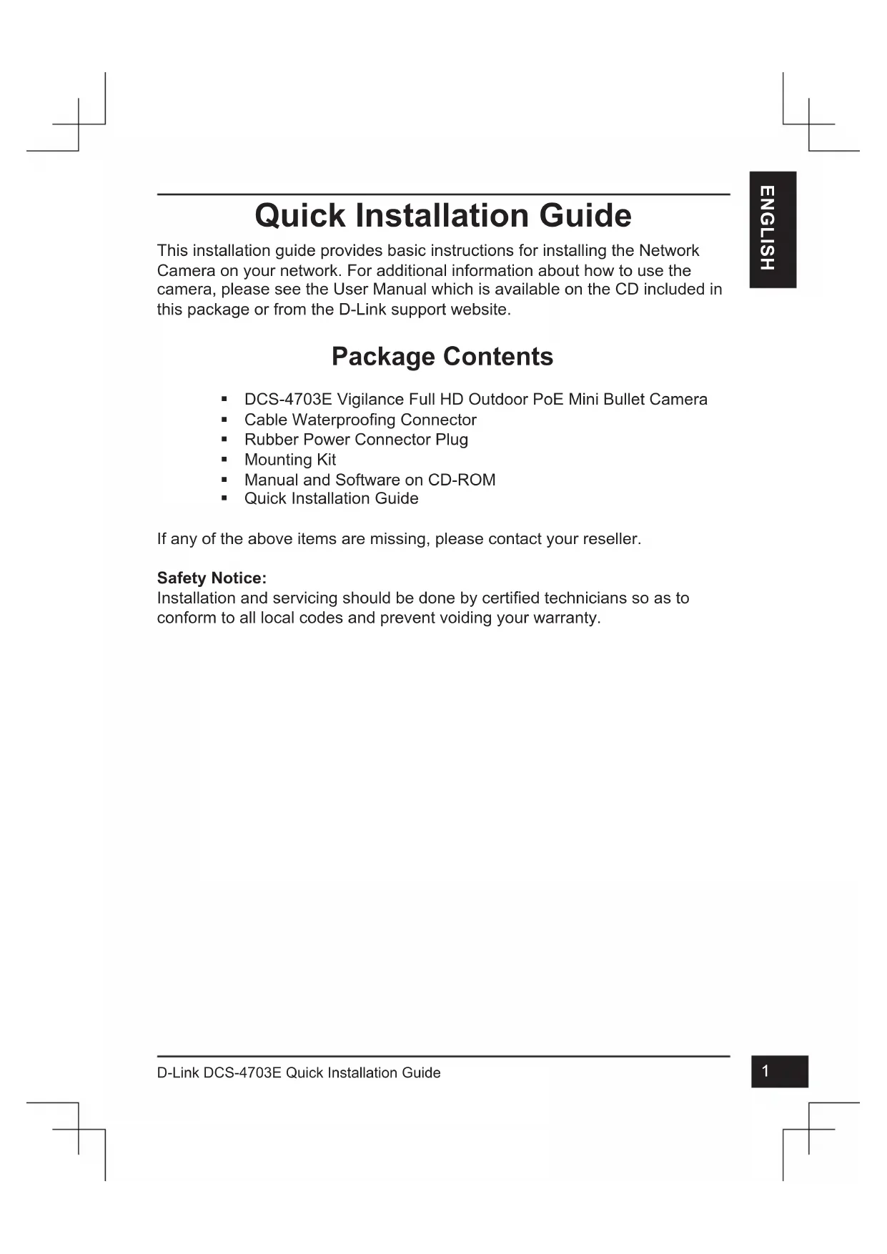
Vigilance Full HD Outdoor PoE Mini Bullet Camera
This document will guide you through the basic installation process for your new D-Link Network Camera.
DCS-4703E
natural_image
Technical line drawing of a mechanical bearing assembly (no text or symbols)Quick Installation Guide
Documentation also available on
CD and via the D-Link Website


Quick Installation Guide
This installation guide provides basic instructions for installing the Network Camera on your network. For additional information about how to use the camera, please see the User Manual which is available on the CD included in this package or from the D-Link support website.
Package Contents
■ DCS-4703E Vigilance Full HD Outdoor PoE Mini Bullet Camera
■ Cable Waterproofing Connector
■ Rubber Power Connector Plug
- Mounting Kit
■ Manual and Software on CD-ROM
■ Quick Installation Guide
If any of the above items are missing, please contact your reseller.
Safety Notice:
Installation and servicing should be done by certified technicians so as to conform to all local codes and prevent voiding your warranty.
Hardware Overview
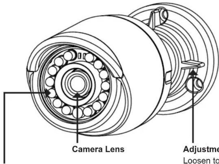
IR LEDs
Provide illumination for low-light environments
Loosen to adjust camera angle and tighten to lock camera angle
Can be attached to a grounding wire if desired
Adjustment Ring
Grounding Screw
natural_image
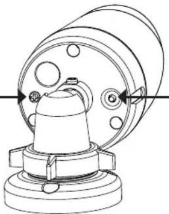
Technical line drawing of a mechanical component with no visible text or symbolsReset Button
Press and hold for 10 seconds to reset camera back to the factory default settings
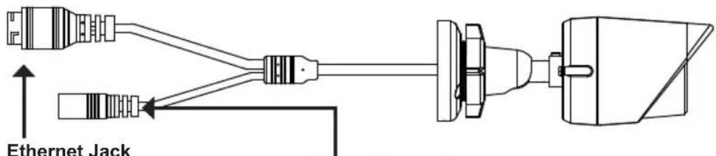
RJ-45 connector for Ethernet, can also be used to power the camera using Power over Ethernet (PoE)
Connects to an optional 12 V / 1.5 A power adapter (not included)
Power Connector
Configuring the Camera
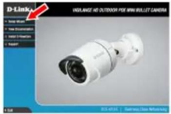
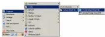
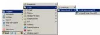
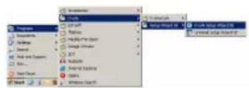
Insert the DCS-4703E CD into your computer's CD-ROM drive to begin the installation. If the Autorun function on your computer is disabled, or if the D-Link Launcher fails to start automatically, click Start > Run. Type D:\ autorun.exe, where D: represents the drive letter of your CD-ROM drive.
Click Setup Wizard and follow the instructions to install the Setup Wizard.
Click on the D-Link Setup Wizard SE icon that was created in your Windows Start menu (Start > D-Link > Setup Wizard SE).
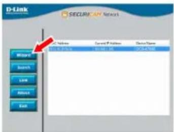
The Setup Wizard will appear and display the MAC address and IP address of your camera(s). If you have a DHCP server on your network, a valid IP Address will be displayed. If your network does not use a DHCP server, the network camera's default static IP 192.168.0.20 will be displayed.
Select your camera, then click the Wizard button to continue.
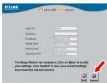
Enter the Admin ID and password. When logging in for the first time, the default Admin ID is admin with the password left blank.
Click the checkboxes if you wish to change the admin ID and password for the camera, and enter the new ID and password you wish to use.

Click Next to continue.
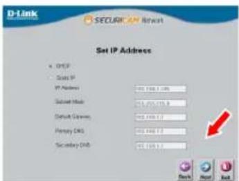
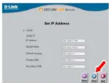
Select DHCP if your camera obtains an IP address automatically from a DHCP server such as a router. Select Static IP if you want to manually enter the IP settings for the camera.
Click Next to continue.
Take a moment to confirm your settings and click Restart.
Viewing Your Camera via Web Browser
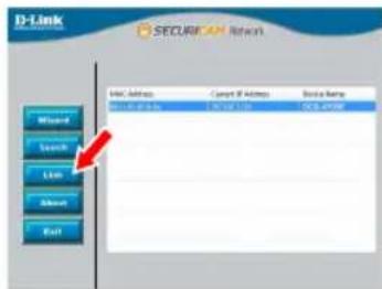
Click on the D-Link Setup Wizard SE icon that was created in your Windows Start menu (Start > D-Link > Setup Wizard SE).
Select the camera and click Link to access the web configuration.
The Setup Wizard will automatically open your web browser to the IP address of the camera.
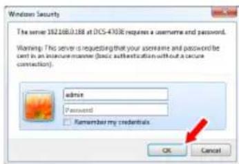
The first time you connect to the camera, you will need to create a password for the administrator account. Enter a password, then click the Save button.
Enter admin as the username and enter the password you just created. Click OK to continue.
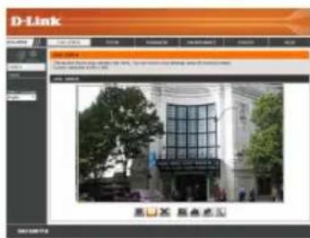
This section displays your camera's live video. You can select your video profile and view or operate the camera. For additional information about web configuration, please refer to the user manual included on the CD-ROM or the D-Link website.

Mounting Instructions
It is highly recommended that you configure and test your camera before mounting it.
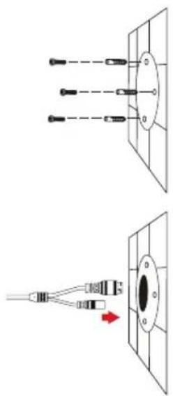
Place the mounting sticker where you want to position the camera. Make sure the camera base will be positioned so that the cable channel is on the bottom.
Use a 6 mm drill bit to make the required holes approximately 25 mm deep, then insert the wall anchors into the holes.
If you are running the camera cables through the wall, drill a hole in the center and pull the cables through the hole.
natural_image
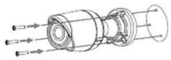
Diagram showing two types of connector or connector assemblies with labeled pins (no text or symbols present)Use the screws provided to mount the camera to the wall.
If you are running the camera cables out the side of the camera, guide the camera cables through the cable channel on the base.
Connect the power and Ethernet cables, or just the Ethernet cable if you are using a PoE connection.
natural_image
Technical line drawing of a mechanical assembly with directional arrows indicating flow or movement (no text or symbols)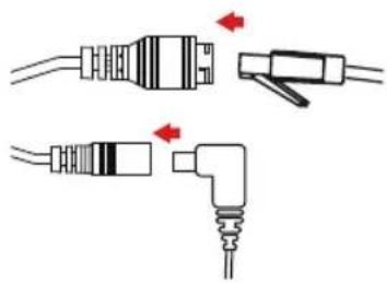
natural_image
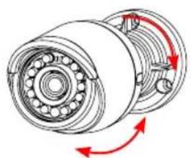
Diagram showing two types of electrical connectors with red arrows indicating connection points (no text or symbols present)To adjust the camera's angle, turn the adjustment ring counterclockwise to loosen it, then move the camera to the desired position and angle. When you are finished, turn the adjustment ring clockwise to tighten it.
natural_image
Mechanical assembly diagram showing a bearing housing with red directional arrows indicating rotational motion (no text or labels)If you need to waterproof your installation, please continue to the next page.
Waterproofing Your Installation
To waterproof your camera installation, follow the instructions below. Round Ethernet cable, a crimping tool, and RJ-45 plugs are required for this procedure.
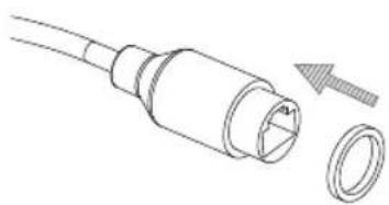
Place the washer around the base of the Ethernet connector as shown.
natural_image
Technical line drawing of a connector with a circular end cap and a separate ring (no text or symbols)Thread bare Ethernet cable through the waterproof connector as shown, then crimp an RJ-45 plug onto the cable.
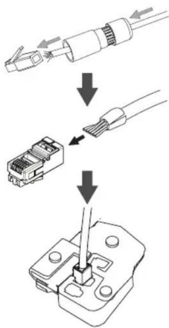
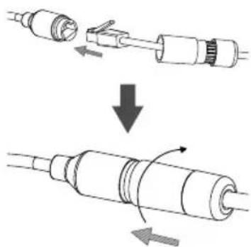
Connect the RJ-45 plug into the Ethernet connector, then screw the waterproof connector to the Ethernet connector by turning it about a half-turn clockwise.
natural_image
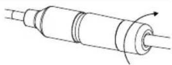
Diagram showing a cable being inserted into a connector, then being repressed or compressed (no text or symbols present)Screw the back part of the waterproof connector clockwise until there is a tight seal around the Ethernet cable.
natural_image
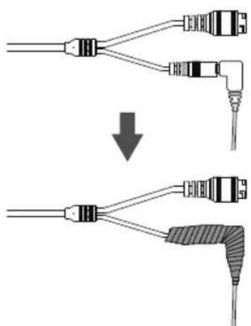
Pure technical line drawing of a cylindrical mechanical component with internal channels and a rotation arrow (no text or symbols)If you are using PoE to power your camera, use the included rubber power connector plug to the power connector.

natural_image
Pure electrical connector diagram showing two USB connectors and a power plug (no text or symbols)If you are using a power adapter(not included) to power your camera, wind waterproof tape around the connection in an overlapping manner to cover it.
Additional Information
Additional help and product information is available online at http://www.dlink.com.
Warranty Information
Please visit http://warranty.dlink.com/ for warranty information for your region.
natural_image
Technical line drawing of a mechanical component with no visible text or symbolsnatural_image
Pure electrical circuit lines without any symbolsEthernet-Anschluss

natural_image
Pure diagram of three parallel lines with dots at the intersection of a central oval (no text or symbols)
natural_image
Diagram showing a connector with wires connected to a circular component, no text or symbols presentnatural_image
Technical line drawing of a mechanical assembly with multiple ports and housing (no text or symbols)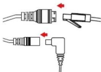
natural_image
Diagram showing two types of electrical connectors with red arrows indicating connection points (no text or symbols present)natural_image
Technical line drawing of a mechanical bearing assembly with red directional arrows indicating rotation (no text or symbols)natural_image
Technical line drawing of a mechanical connector with a separate circular component (no text or symbols)natural_image
Diagram showing a mechanical assembly process with arrows indicating direction of movement (no text or symbols present)natural_image
Pure technical line drawing of a cylindrical mechanical component with internal channels and a rotation arrow (no text or symbols)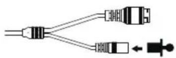
natural_image
Pure electrical connector diagram showing two connected components with a small symbol below (no text or labels)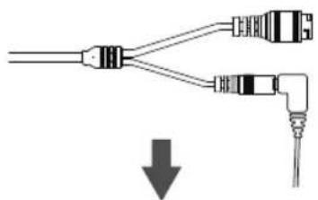
natural_image
Pure diagram of two connected audio/video cables with a downward arrow indicating compression (no text or symbols)
natural_image
Pure electrical connector diagram without any text, numbers, or symbolsnatural_image
Technical line drawing of a mechanical component with no visible text or symbols
natural_image
Diagram showing two types of connector or connector assemblies with pins and connectors, no text or symbols present.natural_image
Technical line drawing of a mechanical assembly with multiple ports and housing (no text or symbols)natural_image
Diagram showing two types of electrical connectors with red arrows indicating connection points (no text or symbols present)natural_image
Technical line drawing of a mechanical assembly with rotating components and red directional arrows indicating motion (no text or symbols)natural_image
Technical line drawing of a mechanical connector with a separate inset showing a ring and a threaded tip (no text or symbols)natural_image
Diagram showing a cable being inserted into a connector, with arrows indicating direction of movement (no text or symbols present)natural_image
Pure technical line drawing of a cylindrical mechanical component with internal channels and a rotation arrow (no text or symbols)natural_image
Pure diagram of two connected cables with a downward arrow indicating connection (no text or symbols)
natural_image
Pure electrical connector diagram without any text, numbers, or symbolsnatural_image
Technical line drawing of a mechanical component with no visible text or symbols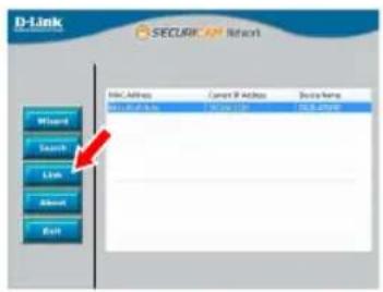
natural_image
Diagram showing two types of connector or connector assemblies with no visible text or symbolsnatural_image
Technical line drawing of a mechanical assembly with directional arrows indicating flow or movement (no text or symbols)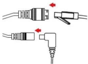
natural_image
Diagram showing two types of electrical connectors with red arrows indicating connection points (no text or symbols present)natural_image
Mechanical assembly diagram showing a bearing housing with red directional arrows indicating rotational motion (no text or labels)natural_image
Technical line drawing of a connector with a screw and plastic housing (no text or symbols)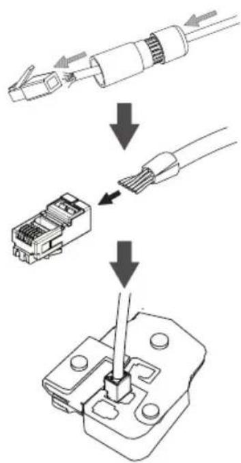
ESPAÑOL
natural_image
Diagram showing a mechanical assembly process with arrows indicating direction of movement (no text or symbols present)natural_image
Pure technical line drawing of a cylindrical mechanical component with internal channels and a rotation arrow (no text or symbols)natural_image
Pure electrical connector diagram showing two USB connectors and a power plug (no text or symbols)natural_image
Pure diagram of two connected audio/video cables with a downward arrow indicating compression (no text or symbols)
natural_image
Pure electrical connector diagram without any text, numbers, or symbolsnatural_image
Technical line drawing of a mechanical component with no visible text or symbolsPulsante di reset
natural_image
Diagram showing two types of electrical connectors with wires and a red arrow indicating connection (no text or symbols present)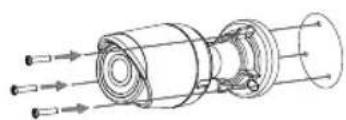
natural_image
Technical line drawing of a mechanical assembly with multiple ports and shafts (no text or symbols)
natural_image
Pure electrical connector diagram showing two types of plug connections with red arrows indicating connection points (no text or symbols)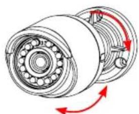
natural_image
Mechanical assembly diagram showing a bearing housing with red arrows indicating rotational direction (no text or labels)natural_image
Technical line drawing of a connector with a screw and plastic housing (no text or symbols)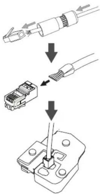
natural_image
Diagram showing a mechanical assembly process with arrows indicating direction of movement (no text or symbols present)natural_image
Pure technical line drawing of a cylindrical mechanical component with internal channels and a rotation arrow (no text or symbols)natural_image
Pure electrical connector diagram showing two USB connectors and a power plug (no text or symbols)natural_image
Technical line drawing of a mechanical component with no visible text or symbolsКнопка Reset
natural_image
Pure diagram of three identical screwdrivers arranged vertically within a rectangular frame (no text or symbols)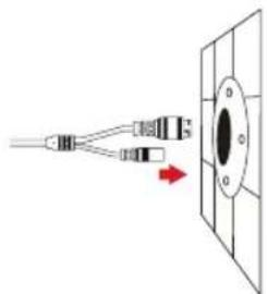
natural_image
Diagram showing a connector or connector inserted into a circular component with a red arrow indicating direction (no text or symbols present)natural_image
Technical line drawing of a mechanical assembly with multiple ports and internal components (no text or symbols)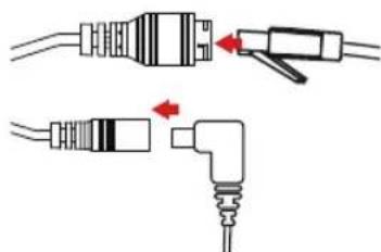
natural_image
Diagram showing two types of electrical connectors with red arrows indicating connection points (no text or symbols present)natural_image
Technical illustration of a mechanical bearing assembly with red directional arrows indicating rotation (no text or symbols)natural_image
Technical line drawing of a connector with a screw and plastic housing (no text or symbols)
natural_image
Diagram showing a cable being inserted into a connector, then being folded into a cylindrical component (no text or symbols present)natural_image
Pure technical line drawing of a cylindrical mechanical component with internal channels and a rotation arrow (no text or symbols)natural_image
Pure electrical connector diagram showing two USB connectors and a power plug (no text or symbols)natural_image
Pure diagram of two connected audio/video cables with a downward arrow indicating connection (no text or symbols)
natural_image
Pure electrical connector diagram without any text, numbers, or symbolsUphill Towers Residence A/99
Ataşehir /ISTANBUL
Tel: +90 (216) 492-99-99
Email: info.tr@dlink.com.tr

תָרִי
20 אַרְשׁוֹת 'ה'
הכלה
תְרָה בַעּו
972 (3) 921-28-86
support@dlink.co.il
natural_image
Technical line drawing of a mechanical component with no visible text or symbolsnatural_image
Diagram showing two types of connector or connector assemblies with pins and connectors, no text or symbols present.natural_image
Technical line drawing of a mechanical assembly with multiple ports and housing (no text or symbols)natural_image
Diagram showing two types of electrical connectors with red arrows indicating connection points (no text or symbols present)natural_image
Technical line drawing of a mechanical bearing assembly with red directional arrows indicating rotation (no text or symbols)natural_image
Technical line drawing of a connector with a screw and plastic housing (no text or symbols)natural_image
Diagram showing a mechanical assembly process with arrows indicating direction of movement (no text or symbols present)natural_image
Pure technical line drawing of a cylindrical mechanical component with internal channels and a rotation arrow (no text or symbols)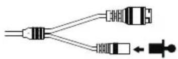
natural_image
Pure electrical connector diagram showing two USB connectors and a power plug (no text or symbols)
natural_image
Pure diagram of two connected audio/video cables with a downward arrow indicating compression (no text or symbols)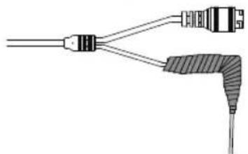
natural_image
Pure electrical connector diagram without any text, numbers, or symbolsnatural_image
Technical line drawing of a mechanical component with no visible text or symbols請點選「Next」來繼續。
透過網頁瀏覽器來觀看攝影機影像
natural_image
Pure diagram of three identical optical components with dashed lines indicating alignment, no text or symbols present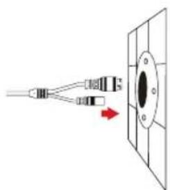
natural_image
Diagram showing a connector emitting a black object into a panel, with a red arrow indicating direction (no text or symbols)natural_image
Technical line drawing of a mechanical assembly with multiple ports and housing (no text or symbols)natural_image
Diagram showing two types of electrical connectors with red arrows indicating connection points (no text or symbols present)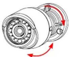
natural_image
Mechanical assembly diagram showing a bearing housing with rotating components and red directional arrows indicating motion (no text or labels)中文
natural_image
Technical line drawing of a connector with a screw and plastic housing (no text or symbols)
natural_image
Diagram showing a cable being inserted into a connector, with arrows indicating direction of movement (no text or symbols present)natural_image
Pure technical line drawing of a cylindrical mechanical component with internal channels and a rotation arrow (no text or symbols)natural_image
Pure electrical connector diagram showing two USB connectors and a plug (no text or symbols)natural_image
Pure diagram of two connected cables with a downward arrow indicating direction (no text or symbols)
natural_image
Pure electrical connector diagram without any text, numbers, or symbols中文
其他資訊
natural_image
Technical line drawing of a mechanical component with no visible text or symbols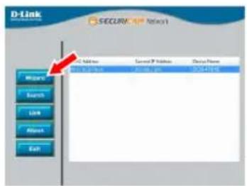

Melihat Kamera Anda via Web Browser
Klik pada ikon D-Link Setup Wizard SE pada menu Start Windows (Start> D-Link> Setup Wizard SE).
natural_image
Diagram showing two types of connector or connector assemblies with pins and connectors, no text or symbols present.natural_image
Technical line drawing of a mechanical assembly with multiple ports and housing (no text or symbols)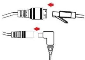
natural_image
Pure electrical connector diagram showing two types of plug connections without any text or symbolsnatural_image
Mechanical assembly diagram showing a bearing housing with rotating components and red directional arrows indicating motion (no text or labels)natural_image
Technical line drawing of a connector with a bolt and ring (no text or symbols)natural_image
Diagram showing a cable being inserted into a connector, with arrows indicating direction of movement (no text or symbols present)natural_image
Pure technical line drawing of a cylindrical mechanical component with internal channels and a rotation arrow (no text or symbols)natural_image
Pure electrical connector diagram showing two USB connectors and a power plug (no text or symbols)natural_image
Pure diagram of two connected audio/video cables with a downward arrow indicating compression (no text or symbols)
natural_image
Pure electrical connector diagram without any text, numbers, or symbolsInformasi Tambahan
Regulatory Statements (Only for Class A product)
Federal Communication Commission Interference Statement
This equipment has been tested and found to comply with the limits for a Class A digital device, pursuant to part 15 of the FCC Rules. These limits are designed to provide reasonable protection against harmful interference when the equipment is operated in a commercial environment. This equipment generates, uses, and can radiate radio frequency energy and, if not installed and used in accordance with the instruction manual, may cause harmful interference to radio communications. Operation of this equipment in a residential area is likely to cause harmful interference in which case the user will be required to correct the interference at his own expense.
Non-modification Statement
Any changes or modifications not expressly approved by the party responsible for compliance could void the user's authority to operate the equipment.
Caution
This device complies with Part 15 of the FCC Rules. Operation is subject to the following two conditions:
(1) This device may not cause harmful interference, and (2) this device must accept any interference received, including interference that may cause undesired operation.
Innovation, Science and Economic Development Canada (ISED) Statement:
This Class A digital apparatus complies with Canadian ICES-003.
CE EMI Class A Warning
This equipment is compliant with Class A of CISPR 32. In a residential environment this equipment may cause radio interference.
Regulatory Statements (Only for Class B product)
Federal Communication Commission Interference Statement
This equipment has been tested and found to comply with the limits for a Class B digital device, pursuant to Part 15 of the FCC Rules. These limits are designed to provide reasonable protection against harmful interference in a residential installation. This equipment generates, uses and can radiate radio frequency energy and, if not installed and used in accordance with the instructions, may cause harmful interference to radio communications. However, there is no guarantee that interference will not occur in a particular installation. If this equipment does cause harmful interference to radio or television reception, which can be determined by turning the equipment off and on, the user is encouraged to try to correct the interference by one of the following measures:
- Reorient or relocate the receiving antenna.
- Increase the separation between the equipment and receiver.
- Connect the equipment into an outlet on a circuit different from that to which the receiver is connected.
- Consult the dealer or an experienced radio/TV technician for help.
Non-modification Statement
Any changes or modifications not expressly approved by the party responsible for compliance could void the user's authority to operate the equipment.
Caution
This device complies with Part 15 of the FCC Rules. Operation is subject to the following two conditions: (1) This device may not cause harmful interference, and (2) this device must accept any interference received, including interference that may cause undesired operation.
Innovation, Science and Economic Development Canada (ISED) Statement:
This Class B digital apparatus complies with Canadian ICES-003.
CE EMI CLASS A WARNING
This equipment is compliant with Class A of CISPR 32. In a residential environment this equipment may cause radio interference.
SAFETY INSTRUCTIONS
The following general safety guidelines are provided to help ensure your own personal safety and protect your product from potential damage. Remember to consult the product user instructions for more details.
- Static electricity can be harmful to electronic components. Discharge static electricity from your body (i.e. touching grounded bare metal) before touching the product.
- Do not attempt to service the product and never disassemble the product. For some products with a user replaceable battery, please read and follow the instructions in the user manual.
- Do not spill food or liquid on your product and never push any objects into the openings of your product.
- Do not use this product near water, areas with high humidity, or condensation unless the product is specifically rated for outdoor application.
- Keep the product away from radiators and other heat sources.
• Always unplug the product from mains power before cleaning and use a dry lint free cloth only.
DISPOSING AND RECYCLING YOUR PRODUCT

This symbol on the product or packaging means that according to local laws and regulations this product should be not be disposed of in the household waste but sent for recycling. Please take it to a collection point designated by your local authorities once it has reached the end of its life, some will accept products for free. By recycling the product and its packaging in this manner you help to conserve the environment and protect human health.
CE EMI KLASSE A-WAARSCHUWING
AFVALVERWERKING EN RECYCLING VAN UW PRODUCT

MISE AU REBUT ET RECYCLAGE DE VOTRE PRODUIT


VIDVÖRUN FYRIR CE EMI FLOKK A
UTYLIZACJA I RECYKLING PRODUKTU

Slovenian [Slovenski]
OPOZORILO CE EMI ZA RAZRED A
DESECHAR Y RECICLAR EL PRODUCTO

CE EMI KLASS A-VARNING
This D-Link product includes software code developed by third parties, including software code subject to the GNU General Public License ("GPL") or GNU Lesser General Public License ("LGPL"). As applicable, the terms of the GPL and LGPL, and information on obtaining access to the GPL code and LGPL code used in this product, are available to view the full GPL Code Statement at:
The GPL code and LGPL code used in this product is distributed WITHOUT ANY WARRANTY and is subject to the copyrights of one or more authors. For details, see the GPL code and the LGPL code for this product and the terms of the GPL and LGPL.
Written Offer for GPL and LGPL Source Code
Where such specific license terms entitle you to the source code of such software, D-Link will provide upon written request via email and/or traditional paper mail the applicable GPL and LGPLsource code files via CD-ROM for a nominal cost to cover shipping and media charges as allowed under the GPL and LGPL.
Please direct all inquiries to:
Email:
GPLCODE@dlink.com
Snail Mail:
Attn: GPLSOURCE REQUEST
D-Link Systems, Inc.
Fountain Valley, CA 92708
Notes
Notes
Notes
Notes


D-Link®

Ver.1.01(WW)_90x130
2018/10/05
RMN0101591A