EM 20 - Exercise bike Christopeit - Free user manual and instructions
Find the device manual for free EM 20 Christopeit in PDF.
User questions about EM 20 Christopeit
0 question about this device. Answer the ones you know or ask your own.
Ask a new question about this device
Download the instructions for your Exercise bike in PDF format for free! Find your manual EM 20 - Christopeit and take your electronic device back in hand. On this page are published all the documents necessary for the use of your device. EM 20 by Christopeit.
USER MANUAL EM 20 Christopeit
Assembly and exercise instructions for Order No. 98201
F
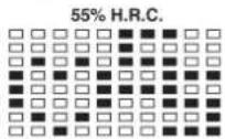
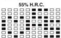
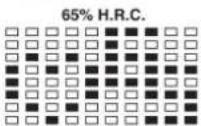
55% H.R.C., 65% H.R.C., 75% H.R.C., 85% H.R.C., Ziel-H.R.C.
One of the Following Six Profiles Will Display Automatically after Measuring Your BODY FAT:
Workout Time: 40 minutes
Workout Time: 40 minutes
Workout time: 20 minutes
Workout Time: 40 minutes
Workout Time: 40 minutes
Workout time: 20 minutes
Trainingsanleitung
- Summary of Parts Page 3
- Important Recommendations and Safety Information Page 14
- Parts List Page 15 - 16
- Assembly Instructions With Exploded Diagrams Page 17 - 19
- Computer instructions Page 20 - 23
- Training Instructions Page 24
Dear customer,
We congratulate you on your purchase of this home training sports unit and hope that we will have a great deal of pleasure with it. Please take heed of the enclosed notes and instructions and follow them closely concerning assembly and use.
Please do not hesitate to contact us at any time if you should have any questions.
Important Recommendations and Safety Instructions
Our products are all TUV-GS tested and therefore represent the highest current safety standards. However, this fact does not make it unnecessary to observe the following principles strictly.
- Assembly the machine exactly as described in the installation instructions and use only the enclosed, specific parts of the machine contained in the parts list. Before assembling, verify the completeness of the delivery against the delivery notice and the completeness of the carton against the parts list in the installation and operating instructions.
- Check the firm seating off all screws, nuts and other connections before using the machine for the first time and at regular intervals to ensure that the trainer is in a safe condition.
- Set up the machine in a dry, level place and protect it from moisture and water. Uneven parts of the floor must be compensated by suitable measures and by the provided adjustable parts of the machine if such are installed. Ensure that no contact occurs with moisture or water.
- Place a suitable base (e.g. rubber mat, wooden board etc.) beneath the machine if the area of the machine must be specially protected against indentations, dirt etc.
- Before beginning training, remove all objects within a radius of 2 metres from the machine.
- Do not use aggressive cleaning agents to clean the machine and employ only the supplied tools or suitable tools of your own to assemble the machine and for any necessary repairs. Remove drops of sweat from the machine immediately after finishing training.
- Your health can be impaired by incorrect or excessive training. Consult a doctor before beginning a planned training programme. He can defi ne the maximum exertion (pulse, Watts, duration of training etc.) to which you may expose yourself and can give you precise information on the correct posture during training, the targets of your training and your diet. Never train after eating large meals.
- Only train on the machine when it is in correct working order. Use original spare parts only for any necessary repairs.
- When setting the adjustable parts, observe the correct position and the marked, maximum setting positions and ensure that the newly adjusted position is correctly secured.
-
Unless otherwise described in the instructions, the machine must only be used for training by one person at a time.
-
Wear training clothes and shoes which are suitable for fitness training with the machine. Your clothes must be such that they cannot catch during training due to their shape (e.g. length). Your training shoes should be appropriate for the trainer, must support your feet firmly and must have non-slip soles.
- If you notice a feeling of dizziness, sickness, chest pain or other abnormal symptoms, stop training and consult a doctor.
- Never forget that sports machines are not toys. They must therefore only be used according to their purpose and by suitably informed and instructed persons.
- People such as children, invalids and handicapped persons should only use the machine in the presence of another person who can give aid and advice. Take suitable measures to ensure that children never use the machine without supervision.
-
Ensure that the person conducting training and other people never move or hold any parts of their body into the vicinity of moving parts.
-
At the end of its life span this product is not allowed to dispose over the normal household waste, but it must be given to an assembly point for the recycling of electric and electronic components. You may find the symbol on the product, on the instructions or on the packing.
The materials are reusable in accordance with their marking. With the re-use, the material utilization or the protection of our environment. Please ask the local administration for the responsible disposal place. - This machine is a speed-independent machine.
- The unit has a resistance device with 16 levels. This makes it possible to increase or reduce the braking resistance and thus the amount of effort required in the training. Pressing the button with an arrow pointing upwards reduces the braking resistance and thus the amount of effort required in the training. Pressing the button with an arrow pointing downwards increases the braking resistance and thus the amount of effort required in the training.
- This machine has been tested and certified in compliance with EN 957-1 and -5 "H,A". The maximum permissible load (=body weight) is specified as 150kg .
Approx. 8 kg flywheel
- Motor- and Computer-controlled resistance
11 installed training programs
-
5 Heart rate programs
-
5 individual programs, resistance adjustable in 10 steps
1 speed independent program, power control in steps of 10 Watt (40-300 Watt)
1 Body fat program
-
Hand pulse measurement
-
Horizontally and vertically adjustable saddle
Saddle and handle bar inclination adjustable
Saddle individual to change
- Wheels for easier transportation
Power plug (Adapter)
-
Computer, showing at same time: Speed, time, distance, approx. calories, body fat analysis, pedal revolutions per minute, Watt and heart rate
-
Input of limits for time, distance and approx. calories
Announcements of higher limits
Fitness test announcement
Max. body weight 150 KG
Space requirement approx.
L 96, W 54, H 135 cm
| Illustration Design No. | Design Dimension Quantity Attached to E mm | number illustration No. | |||
| 1 | Computer | 1 | 15 | 36-9820103-BT | |
| 2 | Handlebar wrapping | 2 | 5 | 36-9820105-BT | |
| 3 | Flat head screw | M 5x10 | 5 | 1+15 | 39-10190 |
| 4 | Handlebar cap | d=25 | 2 | 5 | 39-9847 |
| 5 | Handlebar | 1 | 15 | 33-9808-07-SI | |
| 6 | Hand pulse cable | 2 | 1+19 | 36-9820106-BT | |
| 7 | Upper computer cable | 1 | 1+18 | 36-9820107-BT | |
| 8 | T Knob | 1 | 5 | 36-9613210-BT | |
| 9 | Bushing 1 | 12x1,5x29 | 1 | 8 | 36-9613209-BT |
| 10 | Handlebar cover | 1 | 11 | 36-9613208-BT | |
| 11 | Handlebar fixer | 1 | 15 | 33-9613208-SI | |
| 12 | Spring washer | 10 | 16+68 | 39-9864-VC | |
| 13 L | Pedal crank left | 1 | 43 | 36-9913120-BT | |
| 13 R | Pedal crank right | 1 | 43 | 36-9913121-BT | |
| 14 | Self-tapping screw | M 4x10 | 8 | 54 | 39-10185 |
| 15 | Handlebar post | 1 | 32 | 33-9820102-SI | |
| 16 | Allen key bolt | M 8x16 | 8 | 15+70 | 39-9886-CR |
| 17 | Curved washer | 8//20 | 6 | 16 | 39-10232-CR |
| 18 | Lower computer cable | 1 | 7+20 | 36-9820108-BT | |
| 19 | Pulse unit | 2 | 5 | 36-9613204-BT | |
| 20 | Motor | 1 | 32 | 36-9820109-BT | |
| 21 | Round screw | M 5x13 | 4 | 20 | 39-9903-SW |
| 22 | Saddle | 1 | 24 | 36-9913106-BT | |
| 23 | Square stop | 38x38x1,5 | 2 | 24 | 39-9954 |
| 24 | Saddle adjust set | 1 | 29 | 33-9913103-SI | |
| 25 | Saddle movable set | 1 | 24 | 36-9913107-BT | |
| 27 | Washer | 10//20 | 1 | 28 | 39-10207 |
| 28 | Adjustable Nut | M10 | 1 | 25 | 36-9814-14-BT |
| 29 | Seat post | 1 | 30 | 33-9820103-SI | |
| 30 | Seat post bushing | 1 | 32 | 36-9820110-BT | |
| 31 | Quick release knob | M 14 | 1 | 32 | 36-9613220-BT |
| 32 | Main frame | 1 | 33-9820101-SI | ||
| 33 | Domed Nut | M 8 | 2 | 68 | 39-9900-VC |
| 34 | Sensor connector | 1 | 35 | 36-9808-10-BT | |
| 35 | Sensor | 1 | 32 | 36-9808-09-BT | |
| 36 | Washer | 5//20 | 8 | 14 | 39-10111-VC |
| 37 | C-Clip | d=17 | 2 | 43 | 36-9804-20-BT |
Please check after opening the packing that all the parts shown in the following parts lists are there. Once you are sure that this is the case, you can start assembly.
Please contact us if any components are defective or missing, or if you need any spare parts or replacements in future:
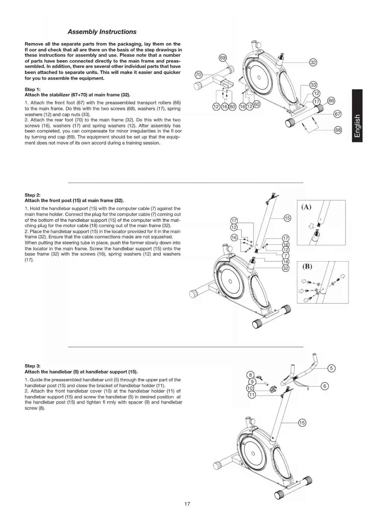
Assembly Instructions
Remove all the separate parts from the packaging, lay them on the floor and check that all are there on the basis of the step drawings in these instructions for assembly and use. Please note that a number of parts have been connected directly to the main frame and preassembled. In addition, there are several other individual parts that have been attached to separate units. This will make it easier and quicker for you to assemble the equipment.
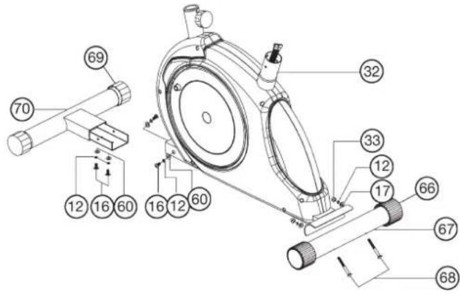
Step 1:
Attach the stabilizer (67 + 70) at main frame (32).
- Attach the front foot (67) with the preassembled transport rollers (66) to the main frame. Do this with the two screws (68), washers (17), spring washers (12) and cap nuts (33).
- Attach the rear foot (70) to the main frame (32). Do this with the two screws (16), washers (17) and spring washers (12). After assembly has been completed, you can compensate for minor irregularities in the floor by turning end cap (69). The equipment should be set up that the equipment does not move of its own accord during a training session.

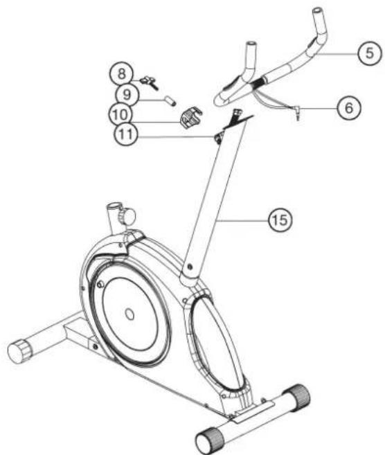
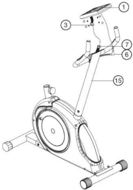
Step 2:
Attach the front post (15) at main frame (32).
- Hold the handlebar support (15) with the computer cable (7) against the main frame holder. Connect the plug for the computer cable (7) coming out of the bottom of the handlebar support (15) of the computer with the matching plug for the motor cable (18) coming out of the main frame (32).
- Place the handlebar support (15) in the locator provided for it in the main frame (32). Ensure that the cable connections made are not squashed. When putting the steering tube in place, push the former slowly down into the locator in the main frame. Screw the handlebar support (15) onto the base frame (32) with the screws (16), spring washers (12) and washers (17).
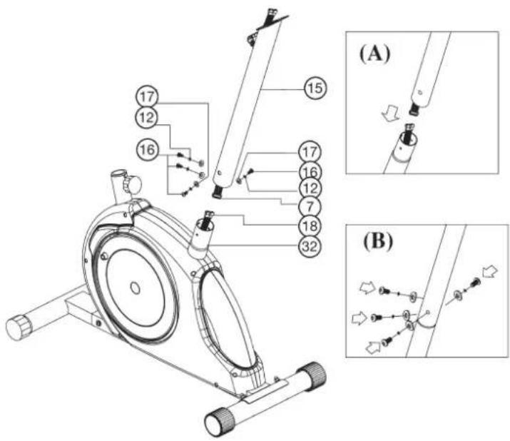
Step 3:
Attach the handlebar (5) at handlebar support (15).
- Guide the preassembled handlebar unit (5) through the upper part of the handlebar post (15) and close the bracket of handlebar holder (11).
- Attach the front handlebar cover (10) at the handlebar holder (11) of handlebar support (15) and screw the handlebar (5) in desired position at the handlebar post (15) and tighten firmly with spacer (9) and handlebar screw (8).

Step 4: Attach the computer (1) at handlebar support (15).
- Push the plug of the connecting cable (7) projecting from the handlebar support (15) into the associated socket of the computer (1).
- Place the computer on the plate provided for it on the handlebar support (15) and attach it with the screws (3).
- Push the plug of the pulse cable (6) projecting from the handlebar (5) into the associated socket of the computer (1).

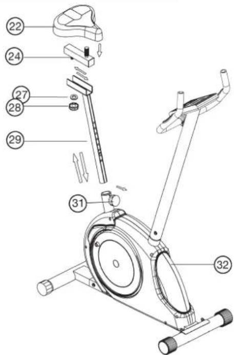
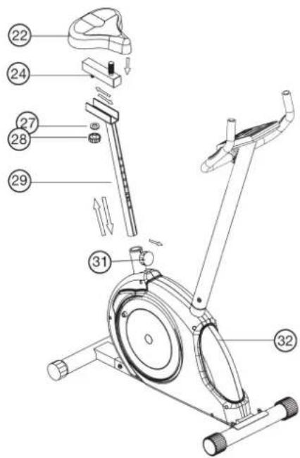
Step 5: Installation of saddle (22) at saddle support (24) by using saddle slide (29).
- Push the saddle (22) with saddle bracket into the movable saddle slide (24) and tight it up in desired position.
- Place the movable seat post (24) into the holder of saddle post (29), set it at the desired horizontally position and tighten it by washer (27) and movable seat knob (28).
- Insert the saddle support (29) into the provided holder of the main frame (32) and secure at the desired position by screwing in the rapid-action lock (31).
(Note: To screw in the rapid-action lock (31), the threaded hole in the main frame (32) and one of the holes in the saddle support (29) must be aligned. Furthermore, ensure that the saddle support (29) is not pulled out of the main frame beyond the marked maximum Position. The setting of the saddle post can be adjusted as desired later. For this, the rapid action catch (31) must be loosened by only a few revolutions, the cap of the lock must be pulled away and the saddle adjusted. Then secure the new setting by tightening the rapid action catch.
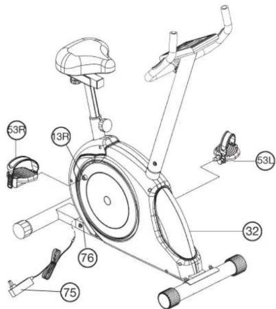
Step 6: Installation of the right pedal (53R) and the left pedal (53L) at pedal arms (13R + 13L) and attach the power adaptor (75).
- Screw the right pedal (53R) into the threaded hole on the right hand side of the pedal arm (13R) and tighten firmly.
(Note: Right and left are specified as viewed seated on the machine during training. It must also be observed that the threaded part of the right pedal must be screwed clockwise into the threaded hole of the pedal crank.) - Screw the left pedal (53L) into the threaded hole on the left hand side of the pedal arm (13L) and tighten firmly.
(Note: The threaded part of the left pedal must be screwed anticlockwise into the threaded hole of the pedal crank.) The pedals are marked "R" for right and "L" for left. - Then attach the pedal straps left and right to the respective pedals.
Step 7:
Attach the power.
- Please insert the plug of adaptor (75) to the jack of chain guard (76).
- Please insert the plug of adaptor (75) to the jack of wall power (230V-50Hz).

Step 8: Checks
- Check the correct installation and function of all screwed and plug connections. Installation is thereby complete.
- When everything is in order, familiarise yourself with the machine at a low resistance setting and make your individual adjustments.
Note: Please keep the tool set and the instructions in a safe place as these may be required for repairs or spare parts orders becoming necessary later.
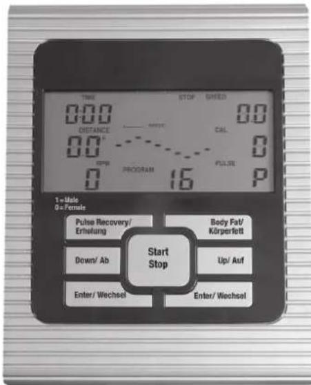
Display Console Overview:

The things you should know before exercise
A. Input Power
Plug in the adaptor to the equipment then the computer will produce a beep sound and turn on the computer at the Manual mode.
B. Program select and setting value
- Use the UP or DOWN keys to select program mode and then press ENTER to confirm your exercise mode.
- At the Manual mode, the computer will use the UP or DOWN keys to set up your exercise TIME, DISTANCE, CALORIES.
- Press the START/STOP key to start exercise.
- When you reach the target, the computer will produce beep sounds and then stop.
- If you set up more than one target and you would like to reach next target, press START/STOP key to keep on exercise.
C. Clock Mode:
- After plug-in AC adaptor then the LCD will display at the Clock mode for user to input the current hour by 24 hours and minute by 60 minutes. After setting up the clock then the monitor will display the hour-minute and second bar on the screen. Two seconds display one bar. Also display the current temperature on the screen. Press any key to quit the CLOCK mode except the ENTER key.
- The computer will enter the clock mode when there is no signal input or no keys be pressed after 4 minutes. You can press ENTER key to switch the clock and temperature at the clock mode or press other keys to quit the clock mode except the ENTER key.
- By holding the ENTER and UP keys together for over two seconds, you can switch to the CLOCK mode during the STOP mode.
- You can set up the CLOCK by holding ENTER key for over 2 seconds when switch to CLOCK mode from STOP mode then you can set up TIME by UP or DOWN keys.
Functions and Features:
- Quick Start key: Allows you to start the computer without selecting a program. TIME automatically begins to count up from zero. Use the UP and DOWN keys to adjust the resistance.
- TIME: Shows your elapsed workout time in minutes and seconds. Your computer will automatically count up from 0:00 to 99:59 in one second intervals. You can also program your computer to count down from a set value by using the UP and DOWN keys. If you continue exercising once the time has reached 0:00, the computer will begin beeping, and reset itself to the original time set, letting you know your workout is done.
- DISTANCE: Displays the accumulative distance traveled during each workout up to a maximum of 99.9KM/MILE.
4.RPM:Your pedal cadence.
- WATT: The amount of mechanical power the computer is receiving from your exercise.
- SPEED: Displays your workout speed value in KM/MILE per hour.
- CALORIES: Your computer will estimate the cumulative calories burned at any given time during your workout.
- PULSE: Your computer displays your pulse rate in beats per minute during your workout.
- AGE: Your computer is age-programmable from 10 to 99 years. If you do not set an age, this function will always default to age 35.
- TARGET HEART RATE (TARGET PULSE): The heart rate you should
maintain is called your Target Hear Rate in beats per minute.
- PULSE RECOVERY: During the START stage, leave the hands holding on grips or leave the chest transmitter attached and then press "PULSE RECOVERY" key, all function displays will stop except "TIME". Time starts counting from 00:60 - 00:59 -- to 00:00. As soon as 00:00 is reached, the computer will show your heart rate recovery status with the grade F1.0 to F6.0.
1.0 means OUTSTANDING
1.0<F<2.0 means EXCELLENT
2.0≤F2.9 means GOOD
3.0F 3.9 means FAIR
4.05.9 means BELOW AVERAGE
6.0 means POOR
Note: If no pulse signal input then the computer will show "P" on the PULSE window. If the computer shows "ERR" on the message window, please re-press the PULSE RECOVERY key and please make sure your hands are keeping well on the grips or the chest transmitter is attached well.
Key function:
There are 6 button keys and the function description as follows:
1. START/STOP key:
a. Quick Start key function: Allows you to start the computer without selecting a program.
Manual workout only. Time automatically begins to count up from zero
b. During the exercise mode, press the key to STOP exercise.
c. During the stop mode, press the key to START exercise.
- UP (Auf) key: a. Press the key to increase the resistance during exercise mode.
b. During the setting mode, press the key to increase the value of Time, Distance, Calories, Age and select Gender and Program.
3. DOWN (Ab) key:
a. Press the key to decrease the resistance during exercise mode.
b. During the setting mode, press the key to decrease the value of Time, Distance, Calories, Age and select Gender and Program.
a. During the setting mode, press the key to accept the current data entry.
b. At the stop mode, by holding this key for over two seconds the user can reset all values to zero or default value.
c. During setting the Clock, press this key can accept the setting hour and setting minute.
5. BODY FAT (Körperfett) key: Press the key to input your HEIGHT, WEKGHT, GENDER and AGE then to measure your body fat ratio,
6. PULSE RECOVERY (Erholung) key: Press the key to activate heart rate recovery function.
Program Introduction & Operation:
Manual Program: Manual
P1 is a manual program. User can start exercise by pressing START/STOP key. The default resistance level is 5. Users may exercise in any desirous of resistance level (Adjusting by UP/DOWN keys during the workout) with a period of time or a number of calories or a certain distance.
Operations:
- Use UP/DOWN keys to select the MANUAL (P1) program.
- Press the ENTER key to enter MANUAL program.
- The TIME will flash and you can press UP or DOWN keys to setting your exercise TIME. Press ENTER key to confirm your desired TIME.
- The DISTANCE will flash and you can press UP or DOWN keys to setting your target DISTANCE.
Press ENTER key to confirm your desired DISTANCE. - The CALORIES will flash and you can press UP or DOWN keys to setting your exercise CALORIES.
Press ENTER key to confirm your desired CALORIES. - Press the START/STOP key to begin exercise.
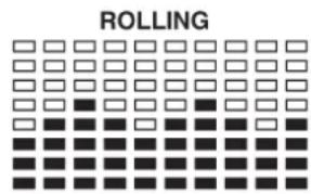
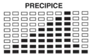
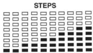
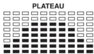
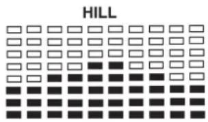
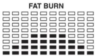
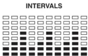
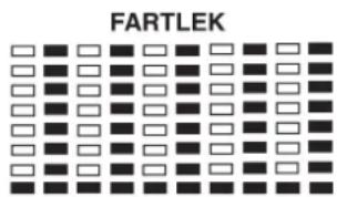
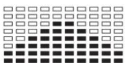
Preset Program: Steps, Hill, Rolling, Valley, Fat Burn, Ramp, Mountain, Intervals, Random, Plateau, Fartlek, Precipice Program
PROGRAM 2 to PROGRAM 13 is the preset programs. Users can exercise with different level of loading in different intervals as the prof les show. Users may exercise in any desirous of resistance level (Adjusting by UP/DOWN keys during the workout) with a period of time or a number of calories or a certain distance.
Operations:
- Use UP/DOWN keys to select one of the above programs from P2 to P13.
- Press the ENTER key to enter your workout program.
- The TIME will flash and you can press UP or DOWN keys to setting your exercise TIME.
Press ENTER key to confirm your desired TIME.
- The DISTANCE will flash and you can press UP or DOWN keys to setting your target DISTANCE.
Press ENTER key to confirm your desired DISTANCE. - The CALORIES will flash and you can press UP or DOWN keys to setting your exercise CALORIES.
Press ENTER key to confirm your desired CALORIES. - Press the START/STOP key to begin exercise.
User Setting Program: User 1, User 2, User 3 and User 4
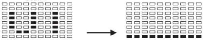
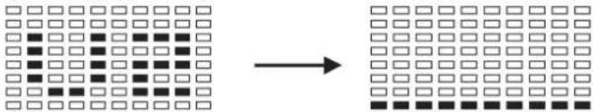
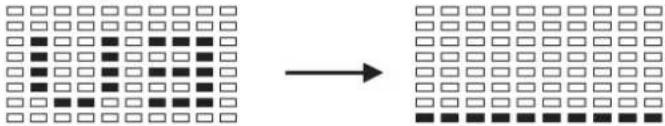
Program 14 to 17 is the user setting program. Users are free to create the values in the order of TIME, DISTANCE, CALORIES and the resistance level in 10 columns. The values and prof les will be stored in the memory after setup. Users may also change the ongoing loading in each column by UP/DOWN keys, and they will not change the resistance level stored in the memory.
Operations:
- Use UP/DOWN keys to select the USER program from P14 to P17.
- Press the ENTER key to enter your workout program.
- The column 1 will flash, and then use the UP/DOWN keys to create your personal exercise profile.
Press ENTER to confirm your first column of exercise profile. The default level is load 1.
4. The column 2 will flash, and then use the UP/DOWN keys to create your personal exercise profile.
Press ENTER to confirm your second column of exercise profile.
5. Follow the above description 5 and 6 to finish your personal exercise profi les.
Press ENTER to confirm your desired exercise profile.
6. The TIME will flash and you can press UP or DOWN keys to setting your exercise TIME.
Press ENTER key to confirm your desired TIME.
7. The DISTANCE will flash and you can press UP or DOWN keys to setting your target DISTANCE.
Press ENTER key to confirm your desired DISTANCE.
8. The CALORIES will flash and you can press UP or DOWN keys to setting your exercise CALORIES.
Press ENTER key to confirm your desired CALORIES.
9. Press the START/STOP key to begin exercise.
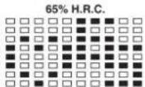
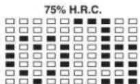
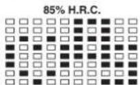
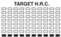
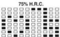
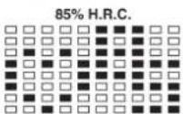
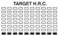
Heart Rate Control Program: 55% H.R.C., 65% H.R.C., 75% H.R.C., 85% H.R.C., Target H.R.C.
Program 18 to Program 22 is the Heart Rate Control Programs and Program 22 is the Target Heart Rate Control program.
Program 18 is the 55% Max H.R.C. -- Target H.R. = (220 - AGE) x 55%
Program 19 is the 65% Max H.R.C. -- Target H.R. = (220 - AGE) x 65%
Program 20 is the 75% Max H.R.C. - - Target H.R. = (220 - AGE) x 75%
Program 21 is the 85% Max H.R.C. -- Target H.R. = (220 - AGE) x 85%
Program 22 is the Target H.R.C. - - Workout by your target heart rate value.
Users can exercise according to your desired Heart Rate program by setting your AGE, TIME, DISTANCE, CALORIES or TARGET PULSE. In these programs, the computer will adjust the resistance level according to the heart rate detected. For example, the resistance level may increase every 20 seconds while the heart rate detected is lower than the TARGET H.R and then the computer will show "SLOW DOWN" on the message window. Also the resistance level may decrease every 20 seconds while the heart rate detected is higher than the TARGET H.R and then the computer will show "HURRY UP" on the message window. As a result, the user's heart rate will be adjusted to close the TARGET H.R. between the range of TARGET H.R. +5 and TARGET H.R. -5 and then the computer will show "KEEP GOING" on the message window.
Operations:
- Use UP/DOWN keys to select one of the heart rate control program from P18 to P22.
- Press the ENTER key to enter your workout program
- The AGE will flash at P18 to P21 programs and you can press UP or DOWN keys to set your AGE.
The default age is 35. - At program 22, the TARGET PULSE will flash and you can press UP or DOWN keys to set your TARGET PULSE between 80 to 180. The default TARGET PULSE is 120.
- The TIME will flash and you can press UP or DOWN keys to set your exercise TIME. Press ENTER key to confirm your desired TIME.
- The DISTANCE will fl ash and you can press UP or DOWN keys to set your target DISTANCE.
Press ENTER key to confirm your desired DISTANCE. - The CALORIES will fl ash and you can press UP or DOWN keys to set your exercise CALORIES.
Press ENTER key to confirm your desired CALORIES. - Press the START/STOP key to begin exercise.
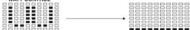
Watt Control Program: Watt Control
Program 23 is a Speed Independent Program. Press ENTER key to set up the values of TARGET WATT, TIME, DISTANCE and CALORIES. During the exercise mode, the level of resistance is not adjustable. For example, the level of resistance may increase while the speed is too slow. Also the level of resistance may decrease while the speed is too fast. As a result, the calculated value of WATT will close to the value of TARGET WATT setup by users.
Operations:
- Use UP or DOWN key to select the WATT CONTROL (P23) program.
- Press ENTER key to enter your workout program.
- The TIME will flash and you can press UP or DOWN key to set your exercise TIME.
Press ENTER key to confirm your desired TIME. - The DISTANCE will flash and you can press UP or DOWN key to set your target DISTANCE. Press ENTER key to confirm your desired DISTANCE.
- The WATT will flash and you can press UP or DOWN key to set your target WATT value. Press ENTER key to confirm your target WATT. The default WATT value is 100.
- The CALORIES will flash and you can press UP or DOWN key to set your exercise CALORIES. Press ENTER key to confirm your desired CALORIES.
- Press the START/STOP key to begin exercise.
NOTE: 1. WATT = TORQUE (KGM) * RPM * 1.03
- In this program, the WATT value will keep constant value. It
means that if you peddle quickly, the resistance level will decre
ase and if you peddle slowly, the resistance level will increase.
Always try to keep you in the same watt value.
Body Fat Program: Body Fat
Program 24 is a special program design to calculate users' body fat ratio and to offer a specific loading profile for users. There are 3 body types divided according to the FAT% calculated.
Type1: BODY FAT% > 27
Type2: 27 ≥ BODYFAT% ≥ 20
Type3:BODY FAT % < 20
The computer will show the test results of FAT PERCENT, BMI and BMR.
Operations:
- Use UP/DOWN keys to select the BODY FAT (P24) program.
- Press the ENTER key to enter your workout program.
- The HEIGHT will flash and you can press UP or DOWN keys to set your HEIGHT.
Press ENTER key to confirm your HEIGHT. The default HEIGHT is 170cm or 5'07'' (5feet 7 inches).
- The WEIGHT will flash and you can press UP or DOWN keys to set your WEIGHT.
Press ENTER key to confirm your WEIGHT. The default WEIGHT is 70kgs or 155lbs. - The GENDER will fl ash and you can press UP or DOWN keys to select your sex. Number 1 means man and number 0 means female. Press ENTER key to confirm your Gender. The default sex is 1 (MAN).
- The AGE will flash and you can press UP or DOWN keys to set your AGE. Press ENTER key to confirm your AGE. The default AGE is 35.
- Press the START/STOP key to begin body fat measurement. If the window show E on the window, please make sure your hands are attached well on the grips or the chest belt is touch well on your body. Then press the START/STOP key again to begin body fat measurement.
- After finished your measurement, the computer will show the values of BMR, BMI and FAT PERCENT on the LCD display. Furthermore, the computer will show your own exercise profile for your body type.
- Press START/STOP key to begin exercise.
Operation guide:
1. Sleep Mode:
The computer will enter the sleep mode when there is no signal input and no keys be pressed after 4 minutes. You can press any key to wake up the computer.
- BMI (Body Mass Index): BMI is a measure of body fat based on height and weight that applies to both adult men and women.
- BMR (Basal Metabolic Rate): Your Basal Metabolic Rate (BMR) shows the number of calories your body needs to operate. This doesn't account for any activity, it's simply the energy needed to sustain a heartbeat, breathing and normal body temperature. It measures the body at rest, not sleep, at room temperature.
Error Message:
E1 (ERROR 1):
Normal state: During workout, when the monitor did not get the count si
gnal from the gear motor more than 4 seconds and check under successive 3 times then the LCD will show E1.
Power on state: The gear motor will return to zero automatically, when the signal of motor cannot be detected for more than 4 seconds then the gear motor's driver will be cut off immediately and show the E1 on the LCD display. All the other digital and function mark are blank, and the output signals are cut off also.
E2 (ERROR 2): When the monitor read the memory data, if the I.D. code is not correct or the memory IC damages then the monitor will show E2 immediately at power on.
E3 (ERROR 3): After 4 seconds by start mode, the computer detects the faulty motor did not leave the zero point then the LCD bar displays "E3".
Technical data of the current adapter
- Available for Input: 230V/50Hz or 60Hz Output: 6V AC/0.5A
- Available for Input: 110V/50Hz or 60Hz Output: 6V AC/0.5A
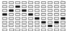
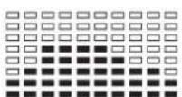
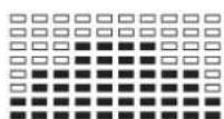
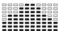
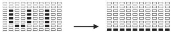
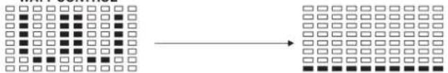
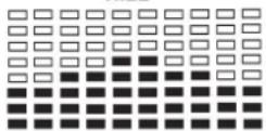
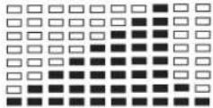
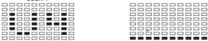
LCD Workout Graphics
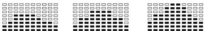
PRESET PROGRAM PROFILES:
PROGRAM 1
PROGRAM 4

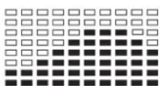
PROGRAM 7

PROGRAM 10
PROGRAM 13
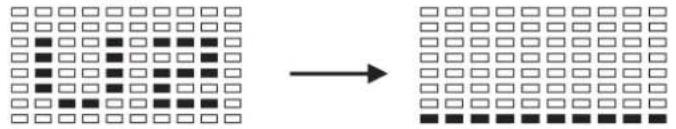
PROGRAM 2

PROGRAM 5

PROGRAM 8
PROGRAM 11
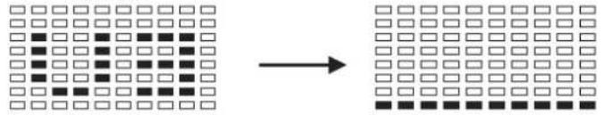
PROGRAM 3
PROGRAM 6
PROGRAM 9
PROGRAM 12
USER SETTING PROGRAM
PROGRAM 14
USER1
PROGRAM 15
USER2
PROGRAM 16
USER3
PROGRAM 17

USER4
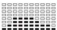
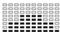
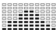
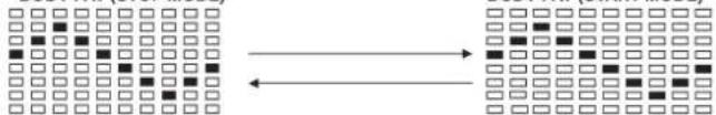
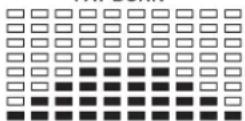
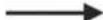
HEART RATE PROGRAM PROFILES:
PROGRAM 18
PROGRAM 19
PROGRAM 20
PROGRAM 21
PROGRAM 22

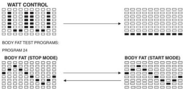
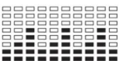
WATT CONTROL PROGRAM
PROGRAM 23
WATT CONTROL
BODY FAT TEST PROGRAMS:
PROGRAM 24
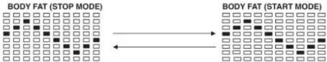
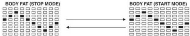
BODY FAT (STOP MODE)
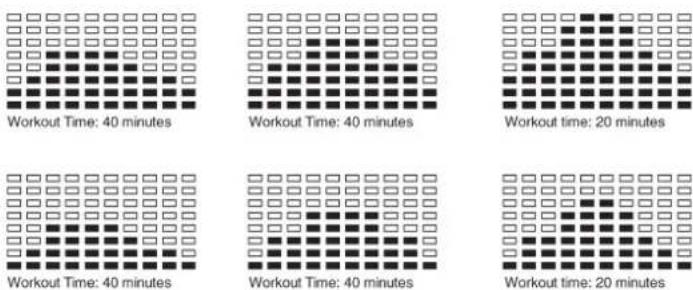
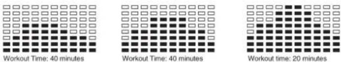
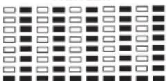
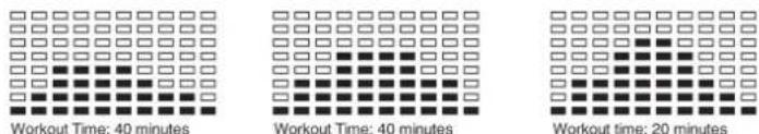
One of the Following Six Profiles Will Display Automatically after Measuring Your BODY FAT:
Workout Time: 40 minutes
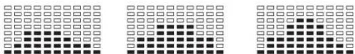
Workout Time: 40 minutes
Workout Time: 40 minutes
Workout time: 20 minutes
Training instructions
You must consider the following factors in determining the amount of training effort required in order to attain tangible physical and health benefits:
1. Intensity:
The level of physical exertion in training must exceed the level of normal exertion without reaching the point of breathlessness and / or exhaustion. A suitable guideline for effective training can be taken from the pulse rate. During training this should rise to the region of between 70% to 85% of the maximum pulse rate (see the table and formular for determination and calculation of this).
During the first weeks, the pulse rate should remain at the lower end of this region, at around 70% of the maximum pulse rate. In the course of the following weeks and months, the pulse rate should be slowly raised to the upper limit of 85% of the maximum pulse rate. The better the physical condition of the person doing the exercise, the more the level of training should be increased to remain in the region of between 70% to 85% of the maximum pulse rate. This should be done by lengthening the time for the training and / or increasing the level of diffi culty.
If the pulse rate is not shown on the computer display or if for safety reasons you wish to check your pulse rate, which could have been displayed wrongly due to error in use, etc., you can do the following:
a. Pulse rate measurement in the conventional way (feeling the pulse at the wrist, for example, and counting the number of beats in one minute).
b. Pulse rate measurement with a suitable specialised device (available from dealers specialising in health-related equipment).
2.Frequency
Most experts recommend a combination of health-conscious nutrition, which must be determined on the basis of your training goal, and physical training three times a week. A normal adult must train twice a week to maintain his current level of condition. At least three training sessions a week are required to improve one's condition and reduce one's weight. Of course the ideal frequency of training is five sessions a week.
3. Planning the training
Each training session should consist of three phases: the warm-up phase, the training phase, and the cool-down phase. The body temperature and oxygen intake should be raised slowly in the warm-up phase. This can be done with gymnastic exercises lasting five to ten minutes.
Then the actual training (training phase) should begin. The training exertion should be relatively low for the first few minutes and then raised over a period of 15 to 30 minutes such that the pulse rate reaches the region of between 70% to 85% of the maximum pulse rate.
In order to support the circulation after the training phase and to prevent aching or strained muscles later, it is necessary to follow the training phase with a cool-down phase. This should be consist of stretching exercises and / or light gymnastic exercises for a period of five to ten minutes.
4. Motivation
The key to a successful program is regular training. You should set a fixed time and place for each day of training and prepare yourself mentally for the training. Only train when you are in the mood for it and always have your goal in view. With continuous training you will be able to see how you are progressing day by day and are approaching your personal training goal bit by bit.
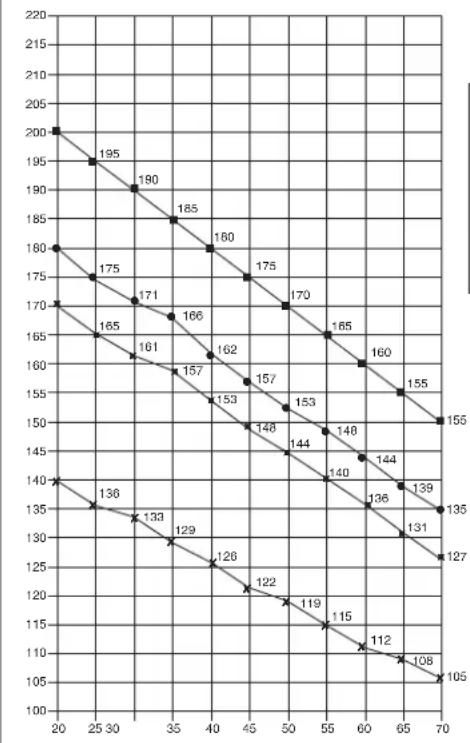
Maximalpuls (220-After) Maximum pulse rate (220-8g)
90% des Maximalpulses 90% of the maximum pulse rate
85% des Maximalpulses 85% of the maximum pulse rate
70% des Maximalpulses 70% of the maximum pulse rate
Calculation formula: Maximum pulse rate = 220 - age (220 minus your age)
90% of the maximum pulse rate = (220 - age) x 0.9
85% of the maximum pulse rate = (220 - age) x 0.85
70% of the maximum pulse rate = (220 - age) x 0.7

Sommaire
Chere cliente, cher client,
PROGRAMME CONTROLLE WATT
PROGRAM 23
One of the Following Six Profiles Will Display Automatically after Measuring Your BODY FAT:
Hartslag Controle Programma: 55% H.R.C., 65% H.R.C., 75% H.R.C., 85% H.R.C., RICHTWAARDE H.R.C.
WATT CONTROLE PROGRAMMA
PROGRAM 23

WATT CONTROL
BODY FAT TEST PROGRAMS:
PROGRAM 24
One of the Following Six Profiles Will Display Automatically after Measuring Your BODY FAT:

3. Planning van de training
War 1: MoHTaX HOKeK (67+70) Ha oCHOBHyO paMy (32).
1.CMOHTnpyuTe nepeDnIOHOxKy (68)c npedBaPntBHo CMOHTnpOBaHHbIMN Ha Hn TpaHCnOpTNPoBOUHbIMN polNKamn (66)Ha OCHOBHyIO paMy (32).Ira 3TOrO nCNoB3yTe NO DBA 60NTa (68),rhTyIe noDKaNDhIE WAIbI (17),npyxINHbIe WAIbI (12) IN KONNaKOBBe raIKK (33).
2. CMoHTpyuTe 3aHIOHOxKy (70) Ha oCHOBHy pamy (32).ДЯ 3TO rO cnoNb3yIte 4 BoTtA (16), noKnlaadHbe Wai6bl (60), npYkunHbIe Wai6bl (12). (Pocne MoTAtka C nOMouBIO KOnJaNA kKeHTpNa (69) npABINbHO bIcTabite KOMNEHCaTOpB HEPOBHOCTNoA. 3TmM Bbl NCKIOHrte HENpeHaMepeHHBe DvIXeHHeN TpeHaeXepa BO BpeM TpeHropBKn.)
War 2: MoHTax onOpHoi Tpy6bl pyra (15) Ha ochOBHyIO pamy (32).
1.Bo3bMnTe onOpHyTOpy6y pyn(15)cnpEaBapntelbHO CMOHTPOBaHbMb CoeHNITeNbHM KAOJEM(7).CoeINHtBe BbXOaIu Chm3y n3 onOPHO Tpy6y pny(15)wTekep coeHNITeNbHorO Ka6en(7)c BbIXoAunM n3 OCHOBnPamb(32)wTekepmKa6en cepBOBnATen(18)
2. BCTaBbTe onophyio ty6y pyn (15) B COOTBeTCTByIOoee KpennneHne Ha OCHOBHOI pame (32).O6paTnte BHNMaHne HA To, TTo6bl Ka6enbHOe coeINHe He 3aueMmNocb H MeDNEHO BCTaBBte ONOPHYO Ty6y pyn (15) CBepxY B COOTBeTCTByIOoee KpennneHne Ha OCHOBHOI pame. PInkpytnte onophyio ty6y pyn (15) K OCHOBHOI (32) C NOMOIO b6IoTOB (16), npyXHHbIX Wai6 (12) nOKnAaHbIX Raek (17).

War 3: MoHTax pyna (5) onopHyIO Tpy6y pyna (15).
1.Повьдente рунь(5)КOTкрытOMу кpenненMu рун(11)Ha onopну trpybe(15)и зakpoNTe erHa pvneM(5).
2. Bctabte nepeHIOO oBnochy pyra (10) Ha pyb (5) n 3akpennte pyb (5) B xenaemoi no3nuiHa onopnoT pybe pyra (15) c nomouho rp6koBoro 6oTa n npomexyTOHOro Tena (9).
War 4: MoHTaX KOMNbIOTepa (1) Ha onophyIO Tpy6y (15).
- BCTaBbTe wTekep KOMnblTePHorO Ka6eH (7), BbIXoJnN n3 OnOpHOr Tpy6bl pynn (15), B HaxoJnueecHa o6paTHoN CTopoHe KOMnblTePa rHe3do (1).
- Bctabte KOMnbIOTep (1) B COOtBeTCTByIOoee KpennHeHa onOpHou Tpy6 pyra (15) (06paTnTe BHNMaHne Ha To, YTO6b Ka6enBHOe CoeINHeHne He 3aueMnAocb), N KpeNko npNKpyTnTe KOMNbIOTep (1) c nOmoBho 6oTob (3) Ha ONPhyIO Tpy6y (15).
3.BCTaBtE WTeKep Ka6eNn N3MepeHn Nynbca (6), BbIXoAun n3 onOpHo Tpy6bl pyNA, B COOTBeTcTByIOoee IHe3Do HA KOMNbIbotepe (1).
Uar 5: MoTax ceNa (22) n cana3ok ceNa (24) Ha onopHyIO Tpy6y ceNa (29).
1.BctabTe ceNo (22)cKpenJIeHHeMaHa cala3Kn ceDna (24) npnKpyTITe ero noJKeJaEMbIM HAKIOHOm.
2. Bctabte cana3kn ce1na (24) B KpennneHne Ha onopHoi Tpy6e ce1na (29) n KpEnKo npikpyTnte ux noJKeJaEMbIM rOp30HaJIbHbIM HAKNOHOM C nOmoBIO rnp6KOBI WAI6bl (28) n NOkNaHOH WAI6bl (27) K ONOPHO Tpy6e ce1na (29).
3.BCTaBtBe onOpHyIO ty6y CeIa (29) B COOTBeTCTByIOuee KpENHeHne Ha OCHOBHO pame (32) n 3aKpeNITe B XeNaEMo N03uIN C NOMOsbIO 6bICTPO3aKpbBaIOUeROc 3aTBopa (31).
(BHIMAHNE!ДЯЗАКРУВАнгБИСТРОЗAKPьВАIOUJOEROC3aTBOPA(31) pe3b6OBOE OTBepCTNe B OCHOBHOr pame (31)и OTBepCTN B ONOPHO TpyeCEcJIa(29)doJXhBI COBnAdaTb.TakKHe npIMnTe BO BHIMAHNE,TO onOpHAR TpyBa CEJNa(29) He DoJXHa BByOXOINb N3 OCHOBHp pAmbla 3a MaKCMAMJIbHyIONoIuIO,ObO3NaYeHHyIO HA OCHOBHp pame.YCTAHOBKa CEJNa MoKET 6bITB B IIOBOE BPemN3MeHEna NO JKeJANIO CNeDyUOMM 6bpa3OM.OTKyPTne H BtIaHIte BbICTPO3AkPbBAIOUmC3aTbOP(31), YCTAHOBITE ONOPHYI Tpy6yCEJNA B HOYIO No3aUeIKBAAHNR 6bICTPO3AKPbBAIOUJOEROC3aTBOPa,NOcNe YeOCHOBA KpeKNo 3aKpyTnTe 6bICTPO3AKPbBAIOUmC3aTBOP.)
Uar 6: MoTax neJaIe (53L+53R) Ha waTyHbI neJaIe (13L+13R).
1.BBepHnTe npabyu neaIb (53R) B npabBn (no HappBeHHIO DnHexeH) wTuyn neaIIN (13R). (BHMAMHe! PpaBO nLeBO onpeJeHTcB nONOxEHm CnHa Na TpeHaepe Bo BPem TpeHnpOBKn. TaKke npMnTE BO BHMAMHe, YTO pe3b0BoE TeNo npAbN BkpyuBaETcB p3e3b0BoEOTBepCTMe B wAuYHe neaNNo YacOBn CTpeKe.)
2. BBeHnTe neByIO neJaIb (53L) B neBbI (no HappaBHeHIO dBHXeHn) 7aTuH neJaII (13L).
(BHIMAHNE! TaKKe npMmTE BO BHIMAHNE, YTo pe3b6OBoe Teno JIeBOI neaII BkpyuINBaETcBpe3b6OBoE OTBepCTHe B WAtyHe neaII npOTNB acOBoi CTpeNke.) IInI ynpoUeHHMOtXaJIeBAI neaII b 603HaueHa 6yKBoi L, a npabai neaJIb 603HaueHa 6yKBoi R.
3.YcTaHOBInTeΦnKcnpyUoUneJeHTbI NeJaEn Ha COOTBeTCTByOuNe neaenn (53R+53L).
7: 10dkJIOueHne 6JIOka NHTAHN (75).
1.BCTaBtE 6TKepe 6noka nHTAHN (75) B COOTBeTcByHOuee rHe3do (76) Ha 3aHem KOHe 06uWbK TpeHaXepa.
2.Bctabte 6nok nTuHnna (75) BtencenbHypo3eTKy (230V/50Hz).
Uar 8: KoHTpoNb
- NpOBeBpTe BCE CoeINHeHnHa npaBnIbHOCTb C6OpKn n npOBeHnTe npOBepKy cyHKUHOHaJIbHOCTn. PpN 3OM MOHTax CHTaETc3aKOHueHHbIM.
2.EcnnBce BnpAke, npoBeInTe np6HyTo TpeHnPoBky npn MaIeHbKo Harpy3Ke, nocne Yero INDnBnDyaBnHO HaCTpoTe TpeHaXep.
3ameyahne:
Noxanycta, CoXpAHnTe HApOp NHCtpyMeHTOB DnR NOcNepdyuxB 803MOKHBxpeMOHTOB INHCTpyKuIO NO MOHTAXy DnR BO3MOKHBx 3aKa3OB 3aNaChbIX YAcTeR.
063op nncnnn:
YTo BbI dOJXHbI 3HaTb nepei nepBoi TpeHnpOBko
KoHTpoIb YacToBc cepDeuHbIX cokpaueHn (HRC): 55% H.R.C., 65% H.R.C., 75% H.R.C., 85% H.R.C., Cenb-H.R.C.
PporgamMb P18-P22 -nporpaMb KoHTpoJIaCToBI cepdeHbIX cokpaueHn. PporpaMa P22 -nporpaMa uebeBOrO nynbc (Target
Heart Rate).
Iporpamma 22-ueeboi nplbc = TpeHnpobKa c Baunm ceJeBbIM nplbcom
Ponb30BaTeMmry Bb6npaTb Jekaemy nporpammy KOHTPOA CTOTbI cepdHbIX COKpaueHHN NocpeCTBOM 3MeHENH Noka3aTeEN BO3pacta, BpeHm, pacToHHN, KAnOpH NZeEBORO nylba. B 3TNX nporpammax CTeHb Harpy3K NcTaHaBnBAeTcB BAtOMATHeCKN B COOTBETBmC qACTOTOn CepdHbIX COKpaueHH. HanpImep, CTeEHb Harpy3Kn YBeHnHuABeTc KaJdbE 20 cek., ecnn qactota cepdeHbIX COKpaueHH NHXe Noka3aTea ZeebeBO rnybcA. Ha Dncnnee BBoDntc "SLOW DOWN / BHIN" (MeJeHee). NIn cTeeHb Harpy3Kn YMeHbAaTc KaaDbE 20 cek., ecnn qactota cepdeHbIX COKpaueHH Biwe Noka3aTea ZeebeBO rnybcA. Ha Dncnnee BBoDntc "HURRY UP / BBEPX" (6bictpee). B pezynbTaTe aactota cepdeHbIX COKpaueHH B obox Cnyaax 6ydtet HaxoDntc B npeDenax 3aDaHHOro noka3aTeen ± 5 . B 3tOM CNYae Ha Dncnnee BBoDntc "KEEP GOING" (npoDoJkaIte).
YnpaBneHne:
- NocpeCTBOM HaxaTnHa KnaBnU UP/DOWN / BBEPX/BHn3 Bbl6epnte Ondy n3 nporpamM P18-P22.
- Haxmte Ha knabuIy ENTER nOITBepxdeHn Bbl6paHno nporpambl.
- Покастел AGE/BO3PACT NaHHaet MraTb. Порседом Нжати Клави UP/BBEPX ИнDown/BH13 BBeДTe CBoB BO3pact. Порсдаховka - 35.net.
- B nporpamme P22 haunhaet mraTb nokaateNB TARGET PULSE/ UENEBOI NylbC. NocpeCTBOM haxatna KnaBn UP/BBEPX nIN DOWN/BHn3 BBeDnte napaemtpbI MeJy 80 n 180 ynapoB BMHyTy. IpeNyctahOBka - 120 ynapoB BMHyTy.
-
Nokaataenb TIME/BPEMHaHnHaet MuraTb. NocpeDcTBom HaxaTnKlaBnUP/BBEPX nn DOWN/BHN3 3aJaTe Bpem TpeHnpOBKn. NocpeDcTBom HaxaTn Ha KlaBnSy ENTER nDTBepdTe Bb6paHoe Bpem TpeHnpOBKn.
-
Noka3aTeIb DISTANCE/PACCTOHHE HaHaHaetMgAtb. NocpeCTBOM HkaTnKnaBnUP/BBEPX nIN DOWN/BHN3 3aJaTe dNCTaHcIO dIa TpeHnpBKn. NocpeCTBOM HkaTnHa KnaBnUY ENTER noITBePdnte BbIbaHHyIO nCTaHcIO TpeHnpBKn.
-
Noka3aTeIb CALORIES/KAJIOPN HAuHaHaET MmraTb. IocpeCTBOM HauKaTIN KNaBnUP/BBEPX mN DOWN/BHn3 3aJaTe KOJIueCTBO KAJOpN, n3pacxOdoBaHHbIX BO Bpemr TpeHnpOBKn. IocpeCTBOM HauKaTIN Ha KnaBnUy ENTER NoDTBepnTe BblpaHHOe KOJIueCTBO KAJOpN, n3pacxOdoBaHHbIX BO Bpemr TpeHnpOBKn.
8.C haxkataHnHa knabuuy START/STOP TpeHnpoBka HauHnaeTcA.
Pporpamma KOHTPONA noka3aTeNBAattax:
Pporpamma P23 - nporpamma Speed Independent Program (He3aBcMma) OT CKOPCTN BpaueHnnporpamma). NocpeCTbOM KlaBmEN ENTER 3aAaTe nokaataenl TARGET WATT/UELEBOI NOKA3ATEb BATT TIME/BPEM, DISTANCE/PACCTORHNE u CALORIES/KAJIOPN. CteneHb Harpy3Kn I3MeHnTb BO Bpem TpeHnpOBKn He BO3MOxHO. Hanpimep, CTeneHb Harpy3Kn MoXet 6bItb YBeJIuYeHa, ecn CIKoPCt b cInkOM Hn3Ka. IN Ho6OpOT, CTeneHb Harpy3Kn MoXet 6bItb YMeHbWeHa, ecn cKoPCt b cInkOM BbcOka. IOn3OMy paCHTbBaembI NOKA3aTeB BATT 6yET np6bnKeH K CEleBOMy NOKa3aTeNIO BATT NOB30BaTeJn.
UnpaBHeHne:
- Посецдом Нжати Ha Клавиши UP/DOWN / BBEPX/BHIN3 Быбэрпт e nporpaMMY P23.
- Haxmte Ha KnaBnSy ENTER nnoTBePKeHn Bb6paHNo nporpaMMbl.
- NokasaTeB TIME/BPEMHaunHaeT MuraTb. NocpeDCTBOM HaxaTnKnaBnUP/BBEPX nn DOWN/BHN3 3aJaTe Bpem TpeHnpOBKn. NocpeDCTBOM HaxaTnHa KaBnSy ENTER noTBePdnte Bbl6paHnoBpEe Bpem TpeHnpOBKn.
4.ПоказATEЛБ DISTANCE/PACCTOHRHHe HauHHeT MnraTb.ПocpeCTBOM haxatma KnaBnUp UP/BBEPX nIu DOWN/BHn3 3aJaTe DictauHIO dIa TpeHnpOBKn.ПocpeCTBOM haxatma Ha KnaBnUy ENTER noITBepnTe BbIbpaHHyIO nIcTaHnIO TpeHnpOBKn. - Noka3aTeNb WATT/BATT NaHaeT MNaTb. NocpeDCTBOM HaxaTnR KnaBnUP/BBEPX nIn DOWN/BHN3 3aJaTe ueJeBoi Noka3aTeNb BaTT. NocpeDCTBOM HaxaTnR Ha KnaBnUy ENTER noTBePnTe Noka3aTeNb. NpdeYctahOBKa Noka3aTeN BATT-100.
- IokaataIb CALORIES/KAIOPNu HAHnHaET Mrratb. IocpeCTBOM Haxatna KnaBn UP/BBEPX nn DOWN/BHN3 3aJaTe KOINueCTBO KAOpni, n3paccxOdoBaHHbIX BO Bpemr TpeHnpOBKn. IocpeCTBOM
Hakatna Ha KlaBniu y ENTER noTBepeDnte BbIbpaHoe KOJIueCTBO KaIopn, n3pacxOdoBaHHbx BO Bpemr TpeHnpOBKn.
7.CHaKaTneM Ha KnaBnSy START/STOP TpeHIpOBKa HaHHaTeCn.
Yka3aHHe:1.WATT MomentBpaueHHKgM*RPM*1,03
2.B30I nporpamme nokaateBbatt He meHnEeTc. Ecn Bbl Bpaaete nean 6bICTpe, CNXaaetc CTeneHb Harpy3Kn, N ecn Bbl Bpaaete nean MeDneHHee, yBemuBaTc CTeneHb Harpy3Kn.
PporpmaOnpeDeneHn coepKaHn Xupa TeNa
Pporpamma P24 - ocobehna nporpaMma. Oha onpeidenet cpeHee KOJIueCTBO Xupa Tena NOIb3ObaTeN I npeJnaraet nporpammy TpeHnOBKn C yuetom paCHTaHHORo noka3aTeN.CyueCTBYOT 3 Tnna TeLOcNOXeHIN, Dn KOTpbIX paCHTbIbAeTc NOKa3aTeIb KOJIueCTBa Xupa B TJeE B npoehtax (FAT %).
Tun 1: Xkp tena > 27
Tun 2:27 ≧ Knp Tena ≥20
Tun 3: Knp tena < 20
KOMBIOTEP BbICBeHnBaet peyntbBTB FAT %, BMI n BMR.
UnpaBneHne:
- NocpeIcTBOM Haxatna Ha KlaBnU UP/DOWN / BBEPX/BHIN3 Bb6epTe nporpammy P24.
- Haxmte Ha KnaBnU ENTER nT BepKdHnB Bb6paHHo nporpaMMbl.
3.Покаразел b HEIGHT/POCT haunhaet miraTb. ПocpeDcTBOM hakatna KlaBn UP/BBEPX nIN DOWN/BHIN3 BBeNTe BaW poC. ПocpeDcTBOM hakatna Ha KlaBnU ENTER noDTBepNTe BBoD. ПрedyTaHObKa -170 CM nIN 5'07"ФYTOB. - NokaataIb WEIGHT/BEc HauHaeT MHaTaIb. IocpeDCTBOM HkaTIN KlaBnUP/BBEPX nn DOWN/BHn3 BBeDnTe BaW Bec. IocpeDCTBOM HkaTIN Ha KnaBnSy ENTER noDTBepnTe BBOd. IpeDyctaHOBka-70 Kr nn 155 cyHTOB.
- NokaataIb GENDER/IOI haunhaeT mRaTb. IocpeDCTBOM haxaTnKnaBnUP/BBEPX nIN DOWN/BHn3 BBeDnte BaW non. Unppa 1O3hauaetMMyckcok》,Uppa0-«KeHcKn. IocpeDCTBOM haxaTnHaKnaBnuy ENTER noITBepDnte BBOI. PpeDyCTAHOBka -1 Myckcok
- NokaTeB AGE/BO3PACT HaHnaeT MraTb. NocpeCTBOM Haxatn KnaBn UP/BBEPX nnDOWN/BHN3 BBeDnte BaW BO3pact. NocpeCTBOM Haxatn Ha KnaBnEY ENTER noDTBepDne BBOd. NpeDyctahOBKa - 35 neT.
7.C haxkatahem Ha KJIaBnUy START/STOP haunhaetcH n3mepeHne JxnpaTeHa.EcnHa dncnnee BbcBeuBaetcE" npOBepbTe, Jekat nn pykn NIOTHo Ha ceHCopax n3MePnteN nyIbca N IIOHTHO nn DaTnK npIneraet K rpydn.
8.После ИЗмереня на диспjee BbICBEчBAIOТС NOKA3aTeNBI BMR, BMIN FAT%ИКOMMbIOTep npednaraet nporpammy c yHTOM pachNTAHORONOKa3aTeNJI
9.C haxkataHem Ha knaBnuy START/STOP TpeHnpOBKa HauHnaeTcA.
Примочаня:
1. Pexmm Stand-By:
Kombotep nepexoont B pexim Stand-By, ecnB teueHne 4 ckynd Tpehaxepom He noIb3ObaNcB. Pnp Haxatm Ha IIObyo KnaBnuy TpeHaXep BKIOUaTcra CHOBA.
- BMI (Body Mass Index): BMI - 3TO NOka3aTeIb JkaPa TeIa, KOTobI b3aHpyETc H aCOoTHoUeHN PoCTa N BeCa N MoKeT PnIMeHATc KaK dJIa XeHUnH, TaK N DJIa MxKUnH.
3.BMR (Basal Metabolic Rate): 3TOT NOKa3aTeBb ONpeDenHET KOINueCTBO KaIOpR, KOTOpBIE Heo6XoDnMbI OprAhn3My DnRA XN3HeDeTEnbHOCTN (dna 6neHHn cepua, dbyxAHn INoDpeKHaHH TEmnpaTpyb TEla).PpN 3OM 3aHTnC nOPTm He yuHTbBAiOTc. N3MepeHnepnoBOHTCR npN KOMHaTHOH TemnepaTy COCTOHN MIOKOR.
Bo3MOxHbIe depeKtbl:
E1(Own6ka1):
HopmaIbHoe coCToHHe: 3Ta OwN6ka BbICBeHbAeTcH Ha DnCIIee BO BpEMr TpeHnpOBKn, ecn DNcPiEi B TeueHHe 4 cekyHd He NOnyHaET CnHnla OT MOTOpa I 3To CNYaETc NOcNeIOBATEbHO Tpu p3a.
BkIOeHoe coToHHe: MToP TpeHaKepa nDet B Honb, ecn 6onee 4 cekyHne He noJyAeT CnHana OT MOTopa. PnpBOD MToTa pca3y Xe OTKIOaETcN Ha DCnIeee BbcBeHbAeTcN HnDnKaTOp "E1". Bce nokaTeEN N FyHKuIN NoTyXaIOT. Bce CnHaNbl BbIXoDAJIne CnHaNbl OKKIOHAcOTcN.
E2(Own6ka 2)
OuNbKa npn CnTbIbAHnn 3aHeceHHbIX B nAmrTaDaHbIX. Ecn Kn LogIn HeBepen Nn nAmrTaIC NOBpeJdeHa, cpa3y Jne nocNe BKJIIOueHn TpeHaepeHa DnCnJIee BBicBeHnBaTeCn INDnKaTOp ,E2".
E3 (Oun6ka 3):
OuB6ka B pexKMe cTAP npn npoeeCTBn 4 cekyH. KombIOTep onpeDenrHeNcnpaBHy moTp n BBicBeHbAeTc Hndikaun "E3".
TexHnueckne daHHbte 6JOKa nHTAHNA
1.ПоIxхояший ДЛВ ВОДа:230V/50Hz mnn 60Hz BBIOd:6V AC/0.5A
2.Подхояшн ДЛВ ВОДа:110V/50Hz mN 60Hz BBIOd:6V AC/0.5A
LCD TpeHnpoBoUhBie rpaΦnKu
BcTpoeHHbI nporpaMMbI TpeHmpoBKn:
PROGRAM 1
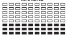
MANUAL
PROGRAM 4
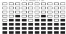
ROLLING
PROGRAM 7
PROGRAM 10
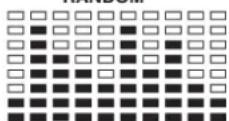
RANDOM
PROGRAM 2
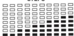
STEPS
PROGRAM 5
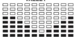
VALLEY
PROGRAM 8
PROGRAM 11
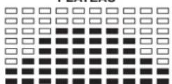
PLATEAU
PROGRAM 3
HILL
PROGRAM 6
FAT BURN
PROGRAM 9
PROGRAM 12
FARTLEK
PROGRAM 13
PRECIPICE
IporpammbiyuHOnyctaHOBKn
PROGRAM 14
USER1
PROGRAM 15
USER 2
PROGRAM 16
USER3
PROGRAM 17
USER 4
Iynbco3aBnCmMbie nporpammbi:
PROGRAM 18
PROGRAM 19
PROGRAM 20
PROGRAM 21
PROGRAM 22
Nporpamma KOHTpOJa NOKa3aTeJI B BaTTax
PROGRAM 23
WATT CONTROL
BODY FAT TEST PROGRAMS:
PROGRAM 24
One of the Following Six Profiles Will Display Automatically after Measuring Your BODY FAT:

BbdoJXhbl yHtBtBaTcNe dyUoune faKTOpbl, YTO6bl ONpeJeNTb BepHbI npaMetpbl TpeHnPOBOK dNRA DOCTUNKEHIN OUYTMbIX fN3Nuecknx pe3yNbTaTOB INoJIb3bl dNRA 3DOPOBBA.
1. HHTeHCMBHOCTb
YpOBeHb Hn3Nuecknx Harpy3OK npn TpeHnpOBkax DoJNKeH npeBbIaTb yPOBeHb HOpMaIbHbIX Hn3Nuecknx HApy3OK, HO Bbl He doJNKnBb 3aDbXaTbcn CmNbHO nepeyTomTbc. YO6HoH mepo3ΦΦeKTHBcHcTn TpeHNPBOK MoKet CnyKuTb cactota nylbca. Bo Bpemr TpeHnpOBKn cactota NybcMAoKet DOCTNRb70-85% OT MAKcMauhON (CMOTPN Tabnuy and pOpymapd AnOnpeDeneHHa pacTa). B nepByIO hAcTota NynbcdoJONHa OCTABaCBA HAHXHeN OTMeTKE 3To ObActn, T.e. OKOn 70% OT MAcMauhBOH. B noCleNyOuue HeDeHN meczbu cactoty Nynbc CneJeT NOCTeNEHO HapaunBaTb do 85% OT MaKcMauhBOH. JyUwe BCero dNn F3NueCKoro COCTORH YALOBEKa, BInONHIOUeO ynpaxHeH, ECn NAcTota Nynbc BO3paTaeT, OCTaBaRb B npeDenax 70-85% OT MAcMauhBOH. 3To DOCTraEeTcB YEINueHEm BpemEH TpeHnpOBKn INyPOBn CNOXHOCTN.
Ecni yactota nybca He nokaHa Ha dncnnee KOMnbIOTepa nn Bby XOTNE npOBepNTb YACTOTy Nylba, KOtopaB, BO3MOXHO, NOKa3Ha HBebpHo, BCneDCTBne KaKo-1n60 Oun6Kn . Bbl MoKeTe ppePnHrtb CJeDyHouee:
© by Top-Sports Gilles GmbH
D-42551 Velbert (Germany)