
ACE184PV0 - Air-conditioner WHIRLPOOL - Free user manual and instructions
Find the device manual for free ACE184PV0 WHIRLPOOL in PDF.

| Product Type | Window/Wall Air Conditioner |
| Brand | Whirlpool |
| Model | ACE184PV0 |
| Weight | 65 to 96 kg (145 to 200 lb) |
| Power Supply | 115 V (103.5-126.5 V) or 230 V (207-253 V), 12-24 A |
| Recommended Fuse | 15 A, 20 A or 30 A time-delay depending on version |
| Operating Modes | Cooling, Dehumidification, Fan, Heating (heat/cool model) |
| Special Features | 6th Sense, RapidCool, Sleep, Timer (30 min to 24 h) |
| Remote Control | Yes, with CR2025 battery |
| Air Filter | Washable, clean every 2 weeks |
| Installation | Window (width 76.2-109.2 cm) or wall (opening 67.9 cm x 47.6 cm) |
| Supplied Parts | Side curtains, seals, mounting flanges, screws, hooks, top rail |
| Safety | Power cord with Test and Reset buttons, ground fault protection |
| Annual Maintenance | Recommended by a certified technician |
Frequently Asked Questions - ACE184PV0 WHIRLPOOL
User questions about ACE184PV0 WHIRLPOOL
0 question about this device. Answer the ones you know or ask your own.
Ask a new question about this device
Download the instructions for your Air-conditioner in PDF format for free! Find your manual ACE184PV0 - WHIRLPOOL and take your electronic device back in hand. On this page are published all the documents necessary for the use of your device. ACE184PV0 by WHIRLPOOL.
USER MANUAL ACE184PV0 WHIRLPOOL
natural_image
Illustration of a thermometer with snowflake patterns around it, no text or symbols present
ROOM AIR CONDITIONER
Use & Care Guide
For questions about features, operation/performance, parts or service, call: 1-877-465-3566.
or visit our website at... www.whirlpool.com
In Canada, for assistance, installation or service, call: 1-800-360-2742
AIR CONDITIONER SAFETY ....3
INSTALLATION REQUIREMENTS....3
Tools and Parts ....3
Location Requirements....4
Electrical Requirements 5
INSTALLATION INSTRUCTIONS......6
Unpack the Air Conditioner....6
Window Installation—Prepare the Cabinet....7
Window Installation—Prepare the Window....8
Window Installation—Position the Cabinet 9
Through-the-Wall Cabinet Installation....11
Complete Installation 12
AIR CONDITIONER USE....13
Starting Your Air Conditioner....13
Using the Remote Control....15
Changing Air Direction 17
Exhaust Air Vent 17
Normal Sounds....17
AIR CONDITIONER CARE ....18
Cleaning the Air Filter 18
Cleaning the Front Panel....18
Repairing Paint Damage 18
Annual Maintenance....18
TROUBLESHOOTING ....18
ASSISTANCE OR SERVICE....20
In the U.S.A. 20
In Canada 20
ÍNDICE
SEGURIDAD DEL ACONDICIONADOR DE AIRE....21
ASSISTANCE OU SERVICE....59
AIR CONDITIONER SAFETY
Your safety and the safety of others are very important.
We have provided many important safety messages in this manual and on your appliance. Always read and obey all safety messages.

This is the safety alert symbol.
This symbol alerts you to potential hazards that can kill or hurt you and others.
All safety messages will follow the safety alert symbol and either the word "DANGER" or "WARNING."
These words mean:
DANGER
You can be killed or seriously injured if you don't immediately follow instructions.
WARNING
You can be killed or seriously injured if you don't follow instructions.
All safety messages will tell you what the potential hazard is, tell you how to reduce the chance of injury, and tell you what can happen if the instructions are not followed.
IMPORTANT SAFETY INSTRUCTIONS
WARNING: To reduce the risk of fire, electrical shock or injury when using your air conditioner, follow these basic precautions:
■ Plug into a grounded 3 prong outlet.
■ Do not remove ground prong.
■ Do not use an adapter.
■ Do not use an extension cord.
■ Unplug air conditioner before servicing.
■ Use two or more people to move and install air conditioner.
SAVE THESE INSTRUCTIONS
INSTALLATION REQUIREMENTS
Tools and Parts
Gather the required tools and parts before starting installation. Read and follow the instructions provided with any tools listed here.
Tools Needed
Phillips screwdriver
Level
■ 1/4" wrench
■ Tape measure
■ Cordless drill and 18 " or smaller bit
■ Pencil
Scissors
Through-the-Wall Installation:
In addition to the tools listed above, the following tools are needed for through-the-wall installation.
■ Saw
■ Wood preservative
Caulk
■ 1" (2.5 cm) or thicker lumber
■ 1" wood screws (7)
Parts Supplied
Check that all parts are included in parts package.
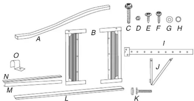
A. Foam seal
B. Side curtains (2)
C. 1½" X ¼" bolts (4)
D. 14 nuts (4)
E. 1/4" screws (23)
F. 3/4" screws (10)
G. Gaskets (10)
H. Lock washers (4)
I. Mounting brackets (2)
J. Angle brackets (2)
K. End caps and leveling legs (2)
L. Adhesive seal
M. Top channel
N. Top channel seal
O. Side curtain clamp (2)
NOTE: Installation parts are supplied for double-hung windows up to 43" (109.2 cm) wide.
Location Requirements
IMPORTANT: Observe all governing codes and ordinances.
Check the location where air conditioner will be installed. Proper installation is your responsibility. Make sure you have everything necessary for correct installation.
The location should provide:
■ Grounded electrical outlet within 4 ft (122 cm) of where the power cord exits the air conditioner.
NOTE: Do not use an extension cord.
■ Free movement of air in room to be cooled.
■ A large enough opening for the air conditioner.
■ Adequate wall support for weight of air conditioner. Air conditioner weighs between 145 and 200 lbs (65 to 96 kg).
NOTE: Cabinet louvers must not be obstructed. Air must be able to pass freely through the cabinet louvers.
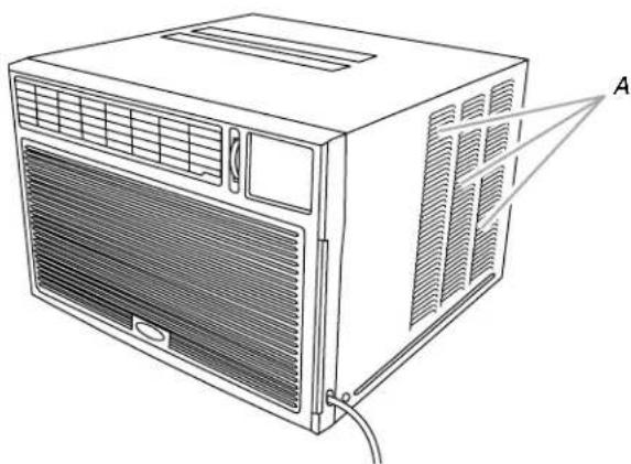
natural_image
Line drawing of an air conditioning unit with ventilation grilles and labeled component A (no text or symbols beyond label)A. Cabinet louvers
Window Installation
Window opening measurements:
■ 30" to 43" (76.2 cm to 109.2 cm) opening width.
■ 19½" (48.6 cm) minimum opening height.
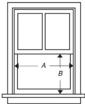
A. 30" (76.2 cm) minimum
B. 19 ^1/8 " (48.6 cm) minimum
Through-the-Wall Installation
The wall opening measurements should be:
■ Width: 26 ^3/4 " (67.9 cm) plus twice thickness of wood used to build frame.
■ Height: 18 ^3/4 " (47.6 cm) plus twice thickness of wood used to build frame.
■ Depth: Dimension for depth depends on the wall thickness and the type of molding.
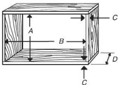
A. 18 ^3/4 " (47.6 cm)
B. 26 ^3/4 " (67.9 cm)
C. Wood thickness
D. Depth
Electrical Requirements
WARNING

Electrical Shock Hazard
Plug into a grounded 3 prong outlet.
Do not remove ground prong.
Do not use an adapter.
Do not use an extension cord.
Failure to follow these instructions can result in death, fire, or electrical shock.
Ground wire must be connected to the ground screw located in the lower right corner of the air conditioner when the air conditioner is in the cabinet.
The electrical ratings for your air conditioner are listed on the model and serial number label. The model and serial number label is located on the right-hand side of the air conditioner cabinet.
Specific electrical requirements are listed in the chart below. Follow the requirements for the type of plug on the power supply cord.
Power Supply Cord Wiring Requirements
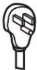 | ■ 115-volt (103.5 min. to 126.5 max.)■ 0 to 12 amps■ 15-amp time-delay fuse or circuit breaker■ Use on single outlet circuit only. | |
14" (0.6 cm) | ■ 230-volt (207 min. to 253 max.)■ 0 to 12 amps■ 15-amp time-delay fuse or circuit breaker■ Use on single outlet circuit only. | |
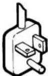 | ■ 230-volt (207 min. to 253 max.)■ 0 to 16 amps■ 20-amp time-delay fuse or circuit breaker■ Use on single outlet circuit only. | |
12" (1.3 cm) | 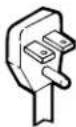 | ■ 230-volt (207 min. to 253 max.)■ 0 to 24 amps■ 30-amp time-delay fuse or circuit breaker■ Use on single outlet circuit only. |
Recommended Grounding Method
This air conditioner must be grounded. This air conditioner is equipped with a power supply cord having a grounded 3 prong plug. To minimize possible shock hazard, the cord must be plugged into a mating, grounded 3 prong outlet, grounded in accordance with all local codes and ordinances. If a mating outlet is not available, it is the customer's responsibility to have a properly grounded 3 prong outlet installed by a qualified electrical installer.
It is the customer's responsibility:
■ To contact a qualified electrical installer.
■ To assure that the electrical installation is adequate and in conformance with National Electrical Code, ANSI/NFPA 70 - latest edition, and all local codes and ordinances.
Copies of the standards listed may be obtained from:
National Fire Protection Association
One Batterymarch Park
Quincy, MÁ 02269
Power Supply Cord
NOTE: Your air conditioner's device may differ from the ones shown.
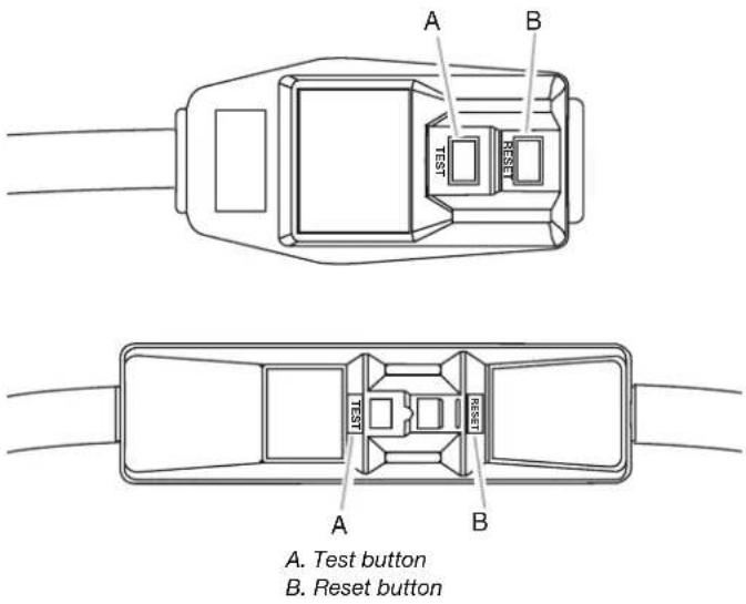
This room air conditioner is equipped with a power supply cord required by UL. This power supply cord contains state-of-the-art electronics that sense leakage current. If the cord is crushed, the electronics detect leakage current and power will be disconnected in a fraction of a second.
WARNING

Electrical Shock Hazard
Plug into a grounded 3 prong outlet.
Do not remove ground prong.
Do not use an adapter.
Do not use an extension cord.
Failure to follow these instructions can result in death, fire, or electrical shock.
- Press RESET (on some devices, a green light will turn on).
- Press TEST (listen for click; Reset button will trip, and on some devices, a green light will turn off).
- Press and release RESET (listen for click; Reset button will latch, and on some devices, a green light will turn on). The power supply cord is ready for operation.
NOTES:
■ The Reset button must be pushed in for proper operation.
■ The power supply cord must be replaced if it fails to trip when the test button is pressed or fails to reset.
■ Do not use the power supply cord as an off/on switch. The power supply cord is designed as a protective device.
■ A damaged power supply cord must be replaced with a new power supply cord obtained from the product manufacturer and must not be repaired.
■ The power supply cord contains no user serviceable parts. Opening the tamper-resistant case voids all warranty and performance claims.
To test your power supply cord:
- Plug the power supply cord into a grounded 3 prong outlet.
INSTALLATION INSTRUCTIONS
Unpack the Air Conditioner
WARNING
Excessive Weight Hazard
Use two or more people to move and install air conditioner.
Failure to do so can result in back or other injury.
Remove packaging materials
■ Remove and dispose of/recycle packaging materials. Remove tape and glue residue from surfaces before turning on the air conditioner. Rub a small amount of liquid dish soap over the adhesive with your fingers. Wipe with warm water and dry.
■ Do not use sharp instruments, rubbing alcohol, flammable fluids, or abrasive cleaners to remove tape or glue. These products can damage the surface of your air conditioner.
■ Handle the air conditioner gently.
1. Remove the air conditioner from the carton and place it on cardboard.
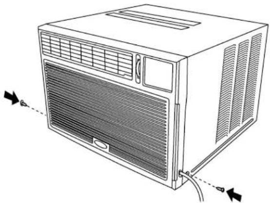
2. Remove the screws that attach the front panel to the air conditioner cabinet on both sides of the air conditioner.
3. Remove the screws that attach the air conditioner cabinet to the base on both sides of the air conditioner.
natural_image
Technical diagram of a heat exchanger or cooling unit with labeled component A (no text or symbols present)A. Screw locations
- Remove the front panel from the air conditioner and set aside.
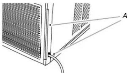
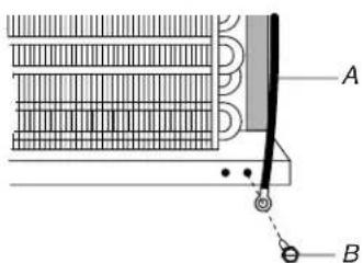
- Remove the ground screw and ground wire from the front of the air conditioner. Save the ground screw.
A. Green ground wire
B. Ground screw
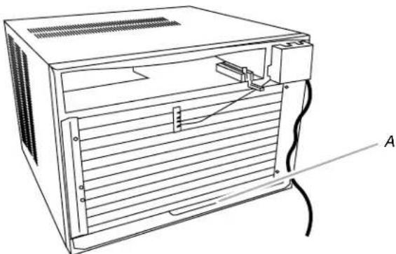
- Pull on the handle to slide the air conditioner out of the cabinet. Place the air conditioner on cardboard.
natural_image
Line drawing of a computer rack unit with ventilation slots and cable, labeled A (no text or symbols on the diagram itself)A. Handle
NOTE: Do not lift, push, pull or remove any expanded polystyrene (foam) from inside the air conditioner. It is not packing material.
Window Installation—Prepare the Cabinet
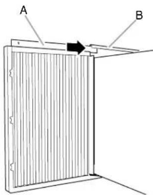
Attach Top Channel
NOTE: Attach the top channel and the side curtains to the air conditioner cabinet before placing the cabinet in the window.
- Locate the bag of screws provided.
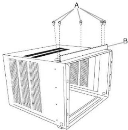
- Attach the top channel seal to the bottom of the top channel.
-
Place the top channel on top of the air conditioner cabinet, lining up the 5 holes in the top channel with the 5 holes on top of the air conditioner cabinet.
-
Using five 1/4" screws, attach the top channel to the air conditioner cabinet.
natural_image
Technical line drawing of a modular air vent or enclosure unit with labeled components A and B (no text or symbols beyond labels)A. 14 " screws B. Top channel
Attach Side Curtains
NOTE: Attach curtains to the air conditioner cabinet before placing the air conditioner cabinet in the window.
- Insert the top and then the bottom of the right-hand curtain housing in the top and bottom curtain guides on the air conditioner cabinet.
Back view
A. Curtain housing
B. Curtain guides
Bottom view
A. Curtain housing
B. Curtain guides
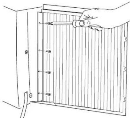
- Extend the right-hand curtain outward so you may insert a 14 " screw through the top hole in the curtain. Using a 14 " screw, screw the curtain to the top hole in the air conditioner cabinet.
NOTE: This screw is required to correctly attach the curtain (top to bottom) to the air conditioner cabinet.
natural_image
Line drawing of a hand holding a tool inside a wooden panel or cabinet frame (no text or symbols)- While the right-hand curtain is still extended, insert 14 " screws through the other three holes in the curtain. Screw the curtain to all four holes in the air conditioner cabinet.
- Slide the curtain housing into the curtain guides as far as it will go.
- Repeat the above steps for the left-hand curtain.
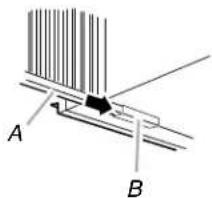
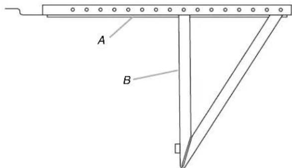
Assemble Mounting and Support Brackets
- Determine the correct holes to attach the support bracket to the mounting bracket. See "Thin-Wall Construction (vinyl, wood, etc.)" or "Thick-Wall Construction (brick)" illustration, depending on installation.
Thin-Wall Construction (vinyl, wood, etc.)
A. Mounting bracket
B. Support bracket
Thick-Wall Construction (brick)
A. Mounting bracket
B. Support bracket
- Insert two 1½" bolts through holes in the mounting bracket and support bracket.
- Place one lock washer and one 14 " nut on each bolt.
NOTE: Do not tighten the nuts as it may be necessary to adjust the location of the support bracket, depending on the thickness of your wall.
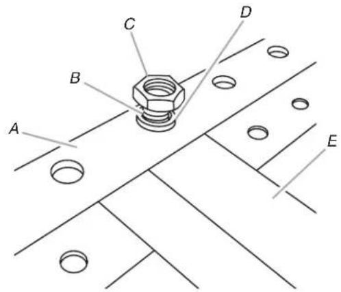
A. Mounting bracket
B. 1½" bolt
C. 1/4" nut
D. Lock washer
E. Support bracket
- Insert the leveling leg into the support bracket.
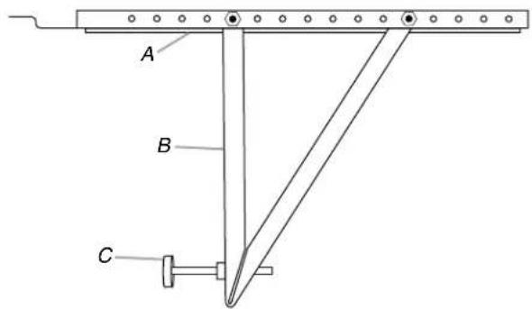
A. Mounting bracket
B. Support bracket
C. Leveling leg
- Repeat for other mounting and support bracket assembly.
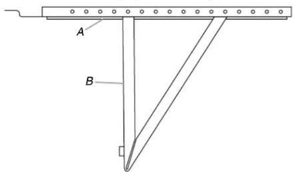
Install Bracket Assembly
- Measure the width of the window opening and mark the center line on the outside windowsill.
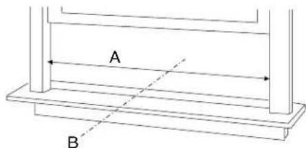
A. Width of window opening
B. Center line
- Measure and mark a line 12^9/16 on each side of the center line.
- Place the bracket assembly in the window. Check to see if the bracket assembly matches the wall construction.
- Using the leveling leg, adjust the angle of the bracket assembly to a downward slope no more than 316 " to allow condensation to flow away from the window.
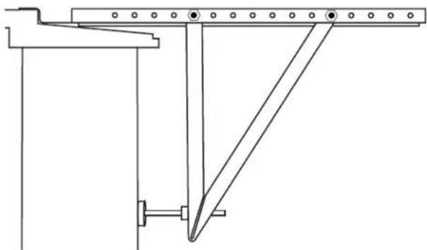
natural_image
Pure technical line drawing of a mechanical structure without any text, numbers, or symbols- If necessary, remove the 1½" bolt, locking washer and ¼" nut, and move the support bracket to the correct holes on the mounting bracket to match the wall construction. Reinsert the 1½" bolt, locking washer and ¼" nut.
- Tighten 14 " nut with a 14 " wrench.
- Align the V-slot with the lines marked in Step 2.
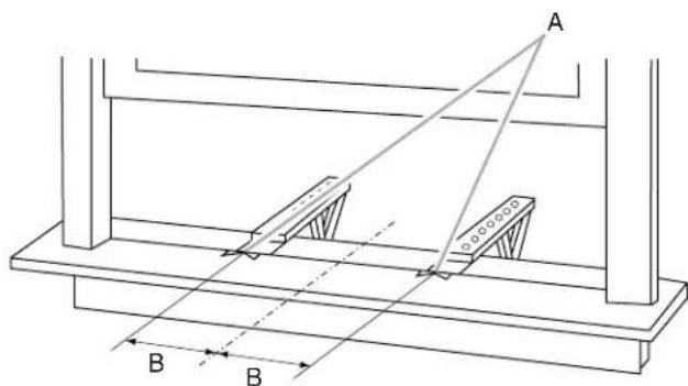
A. V-slots
B. 12% from center line
- Use 18 " drill bit to drill starter holes for each of the two bracket assemblies.
- Using 34 " screws, attach each bracket assembly to the windowsill.
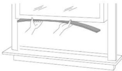
Attach Adhesive Seal
- Cut the adhesive seal to the width of the lower window sash.
- Remove the backing from the seal and attach the seal to the bottom of the lower window sash.
natural_image
Line drawing of a person holding a curved object inside a transparent container (no text or symbols)Window Installation—Position the Cabinet
NOTES:
■ Handle the air conditioner gently.
■ Be sure your air conditioner cabinet does not fall out of the opening during installation or removal.
■ The location where the power cord exits the air conditioner should be no more than 4 ft (122 cm) from a grounded 3 prong outlet.
■ Do not block the louvers on the front panel.
■ Do not block the louvers on the outside of the air conditioner.
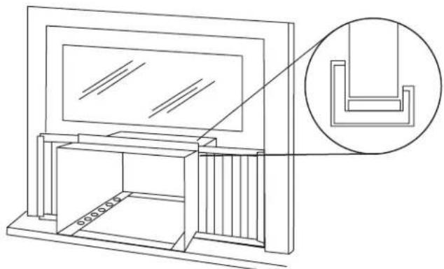
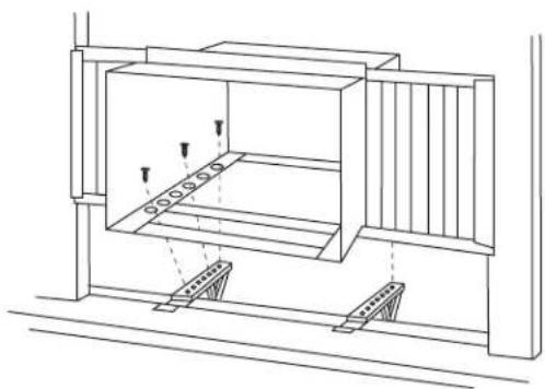
- Center the empty cabinet in the window. Check that the bottom curtain guide on the air conditioner cabinet is inside the track provided by the bracket assemblies. Maintain a firm hold on the air conditioner cabinet. Lower the window sash behind the top channel.
natural_image
Technical line drawing of a cabinet or enclosure with an inset showing a detailed L-shaped component (no text or symbols present)- Align holes in the bottom of the air conditioner cabinet with holes in the bracket assembly.
- Use three 14 " screws to attach the air conditioner cabinet to bracket assembly.
natural_image
Technical line drawing of a mechanical assembly with supports and structural elements (no text or symbols)- Repeat steps 2 and 3 to attach the other side of the air conditioner cabinet to the bracket assembly.
- Check that air conditioner cabinet is tilted to the outside so that water will run to the outside. If needed, adjust the leveling leg.
Attach Side Curtains to Window
- Pull the left-hand curtain out until it fits into the window channel.
- Use 18 " drill bit to drill a starter hole through the hole in the side curtain and window sash.
- Insert one of the 34 " screws through the left-hand curtain and into the window sash.
- Repeat for the right-hand curtain.
Window Sash View
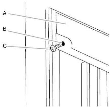
A. Window sash
C. 34 " screw
B. Hole in side curtain
- Use 18 " drill bit to drill a starter hole through the hole in the shutter clamp and windowsill.
- Insert one of the 34 " screws through the hole in the side curtain clamp and into the windowsill.
- Repeat for right-hand curtain.
Windowsill View
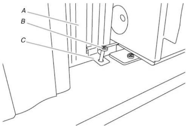
A. Side curtain
B. 34 screw
C. Side curtain clamp
Complete Window Installation
Insert foam seal behind the top of the lower window sash and against the glass of the upper window.
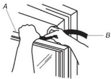
A. Top of lower window sash
B. Foam seal
Through-the-Wall Cabinet Installation
NOTES:
■ Handle the air conditioner gently.
■ Be sure your air conditioner cabinet does not fall out of the opening during installation or removal.
■ The location where the power cord exits the air conditioner should be no more than 4 ft (122 cm) from a grounded 3 prong outlet.
■ Do not block the louvers on the front panel.
■ Do not block the louvers on the outside of the air conditioner.
■ It is the customer's responsibility and obligation to have this product installed by a qualified technician familiar with through-the-wall room air conditioner installations.
Option 1—Wood, metal or plastic molding
When using a wood, metal or plastic molding, the wood frame should line up with the inside wall as shown.
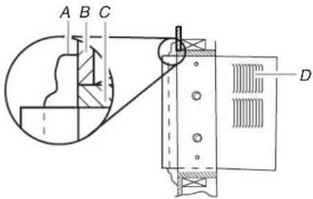
A. Molding
C. Wood frame
B. Inside wall
D. Louvers
Option 2—Plastered wall with no molding
If the plastered wall is to be flush with the cabinet and no molding is used, the wood frame must be set 12 " (13 mm) into the inside wall.
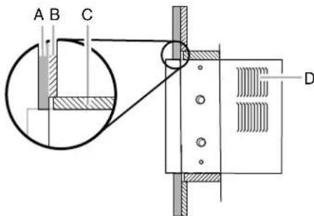
A. Plastered wall
C. Wood frame
B. Inside wall
D. Louvers
Install Wood Frame
- Construct the wood frame. See "Location Requirements" for dimensions.
- Measure the outside width and height of the frame to determine the wall opening dimensions.
- Cut the opening through the wall. Remove and save the insulation.
NOTES:
■ Dimension for depth depends on the wall thickness and the type of molding.
■ Do not block louvers in the air conditioner cabinet.
■ Use 1" (2.5 cm) or thicker lumber for the wood frame.
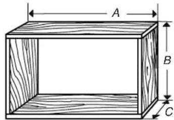
A. Outside width
C. Depth
B. Outside height
- Apply the wood preservative to the outside exposed surface.
- Insert the frame in the wall opening. Square and level the frame.
- Attach the frame securely to the wall.
Install Cabinet into Wood Frame
- Insert the cabinet into the framed wall opening.
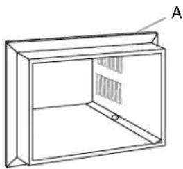
natural_image
Line drawing of a cabinet or enclosure with labeled section A (no text or symbols on the diagram itself)A. Trim
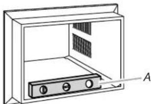
- Use a level to check that the cabinet is level side to side.
natural_image
Line drawing of a cabinet with an open door and internal components, labeled A (no text or symbols on the diagram itself)A. Level
- Check that the air conditioner cabinet is tilted to the outside so that water will run to the outside.
Complete Through-the-Wall Installation
- Reuse the insulation to seal opening between the cabinet and the frame.
- Use the existing holes and six 1" (2.5 cm) wood screws (not provided) to attach the cabinet to the frame.
NOTE: Do not overtighten the screws or the cabinet will distort and provide a poor air seal between the cabinet and the air conditioner. - Caulk all outside wall openings around the cabinet.
Complete Installation
NOTE: Handle the air conditioner gently.
- Make sure the free end of the ground wire is outside of the cabinet.
WARNING
Excessive Weight Hazard
Use two or more people to move and install air conditioner.
Failure to do so can result in back or other injury.
- Insert the air conditioner into cabinet.
NOTE: Make sure the free end of the ground wire is outside of the cabinet.
natural_image
Diagram of a microwave oven with labeled component A, showing internal wiring and housing (no text or symbols beyond label)A. Ground wire outside of the cabinet
WARNING

Electrical Shock Hazard
Connect green ground wire to ground screw.
Failure to do so can result in death or electrical shock.
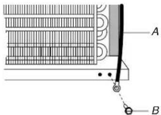
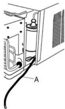
- Connect the green ground wire to the ground screw.
Position the ground wire pointing straight up. Put the excess ground wire between the coil and the air conditioner cabinet.
A. Green ground wire
B. Ground screw
-
Reinstall the two screws that attach the cabinet to the base.
-
Push the front panel straight on and then lower it slightly to lock it into place.
-
Reinstall the two screws to attach the front panel to the air conditioner cabinet.
natural_image
Line drawing of a portable air conditioner unit with ventilation grilles and cooling fins (no text or symbols)NOTE: For through-the-wall installations, if needed, install the molding around the room side of cabinet.
WARNING

Electrical Shock Hazard
Plug into a grounded 3 prong outlet.
Do not remove ground prong.
Do not use an adapter.
Do not use an extension cord.
Failure to follow these instructions can result in death, fire, or electrical shock.
-
Plug into a grounded 3 prong outlet.
-
Press RESET on the power supply cord. See "Electrical Requirements."
AIR CONDITIONER USE
Operating your air conditioner properly helps you to obtain the best possible results.
This section explains proper air conditioner operation.
IMPORTANT:
■ If you turn off the air conditioner, wait at least 3 minutes before turning it back on. This prevents the air conditioner from blowing a fuse or tripping a circuit breaker.
■ Do not try to operate your air conditioner in the Cool mode when outside temperature is below 65^ F ( 18^ C). The inside evaporator coil will freeze up, and the air conditioner will not operate properly.
NOTE: In the event of a power failure, your air conditioner will operate at the previous settings when the power is restored.
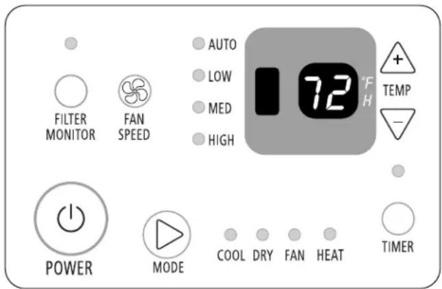
Starting Your Air Conditioner
Cool Only Models Heat/Cool Models
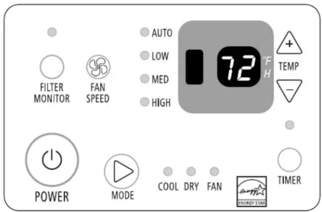
NOTE: When the air conditioner is set to Fan mode and the room temperature is below 32^ F ( 0^ C), the display will show LO. If the room temperature is above 99^ F ( 37^ C), the display will show HI.
- Remove the clear protective film from the front panel badge.
- Press the power button to turn on the air conditioner.

POWER
NOTE: When the air conditioner is turned on for the first time after it is plugged in, the display will show the current room temperature and will run in the 6 ^th Sense ^TM System control. When the air conditioner is turned on at all other times, the display will show the previous settings for 5 seconds, and then show the current room temperature.
- Select mode. See "Mode."
- Select fan speed. See "Fan Speed."
- Set temperature. See "Temperature."
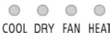
Mode
- Press MODE until you see the indicator light glow for the desired setting.
- Choose Cool, Dry, Fan or Heat (Heat/Cool models only).
Cool—Cools the room. Press FAN SPEED to select High, Med, Low or Auto. Press the plus or minus TEMP button to adjust the temperature.
■ Dry—Dries the room. The air conditioner automatically selects the temperature. Fan runs on Low speed only.
NOTE: Dry mode should not be used to cool the room.
■ Fan—Only the fan runs. Press FAN SPEED to select High, Med or Low. The display shows the current room temperature.
NOTE: Auto fan speed cannot be selected in Fan mode.
■ Heat (Heat/Cool models only)—Heats the room. Press FAN SPEED to select High, Med, Low or Auto. Press the plus or minus TEMP buttons to adjust the temperature.

MODE
NOTE: After 5 seconds, the display will show the current room temperature.
Fan Speed
NOTE: The Fan Speed button will operate only when the Cool, Fan or Heat (Heat/Cool models only) mode has been selected.
- Press FAN SPEED until you see the indicator light glow for the desired setting.
- Choose High, Med, Low or Auto.
■ High—for maximum cooling or heating (Heat/Cool models only)
■ Med—for normal cooling or heating (Heat/Cool models only)
■ Low—for sleeping comfort
■ Auto—automatically controls the fan speed depending on the current room temperature and temperature control setting
NOTE: Auto fan speed cannot be selected in Fan mode.
AUTO

FAN SPEED
- LOW
MED
HIGH
NOTE: After 5 seconds, the display will show the current room temperature.
Filter Monitor
- When Filter Monitor indicator light is lit, remove, clean and replace air filter. See "Cleaning the Air Filter."
- Press FILTER MONITOR after cleaning and replacing the air filter. This resets the filter monitor.


FILTER MONITOR
NOTE: After 360 hours of fan operating time, the filter indicator light will turn on. It will remain on for 180 hours or until you press FILTER MONITOR. After 180 hours, it will turn off automatically.
Temperature
■ Press the plus TEMP button to raise the temperature. Each time you press or hold the plus TEMP button, the temperature will go up 2°F (1°C) until it reaches 90°F (32°C).
NOTE: After 5 seconds, the display will show the current room temperature.
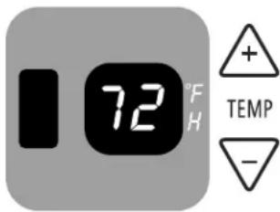
■ Press the minus TEMP button to lower the temperature. Each time you press or hold the minus TEMP button, the temperature will go down 2°F (1°C) until it reaches 64°F (18°C).
NOTE: After 5 seconds, the display will show the current room temperature.
Timer Delay
To set the Timer for a 30-minute to 24-hour delay until the air conditioner turns off (the air conditioner must be On):
- Press TIMER. Timer indicator light will flash. Display will show remaining hours before the air conditioner will turn off.

- Press the plus or minus TEMP button to change the delay time from 30 minutes to 24 hours.
- After 5 seconds, Timer indicator light will remain on. Display will show the current room temperature.
To set the Timer to turn on the air conditioner, keeping previous settings:
- Turn off air conditioner.
- Press TIMER. Timer indicator light will flash. Display will show remaining hours before the air conditioner will turn on.
- Press the plus or minus TEMP button to change the delay time from 30 minutes to 24 hours.
- After 5 seconds, Timer indicator light will remain on. Display will show the current room temperature.
To set the Timer to turn on the air conditioner, changing the previous settings:
- Turn on air conditioner.
- Adjust the mode to Cool, Dry, Fan or Heat (Heat/Cool models only).
- For Cool or Heat (Heat/Cool models only) mode:
■ Adjust fan speed to High, Med, Low or Auto.
■ Adjust temperature between 64°F and 90°F (18°C and 32°C).
- For Fan mode, adjust fan speed to High, Med or Low.
NOTE: In Fan mode, temperature cannot be set.
- For Dry mode, adjust temperature up or down by 4^ F ( 2^ C).
- Turn off air conditioner.
- Press TIMER. Timer indicator light will flash. Display will show remaining hours before the air conditioner will turn on.
-
Press the plus or minus TEMP button to change the delay time from 30 minutes to 24 hours.
-
After 5 seconds, Timer indicator light will remain on. Display will show the current room temperature.
To clear Timer delay program:
NOTE: Air conditioner can be either on or off.
- Press TIMER once after it has been programmed. Display will show remaining time.
- While the display is showing the remaining time, press TIMER again. Timer indicator light will turn off.
To see or change the remaining time (in hours):
- Press TIMER once after it has been programmed. Display will show remaining time.
- While the display is showing the remaining time, press the plus or minus TEMP button to increase or decrease the time.
- After 5 seconds, the display will show the current room temperature.
Using the Remote Control
NOTE: Remote control may differ in appearance.
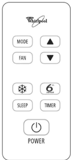
NOTE: One CR2025 battery (included) powers the remote control. Replace battery after 6 months of use, or when the remote control starts to lose power.
Power
Press POWER to turn on air conditioner.

Mode
Press MODE to select Cool, Dry, Fan or Heat (Heat/Cool models only).

6 ^th Sense ^™ System Control
The air conditioner automatically selects Cool or Dry mode, depending on room temperature and sets the temperature to 79^ F ( 26^ C).
■ The temperature set point can be adjusted down to 75^ F ( 24^ C) or up to 83^ F ( 28^ C). Press the up or down arrow button once to change the temperature 2^ F ( 1^ C) or twice to change it 4^ F ( 2^ C).
■ If the current room temperature is lower than the temperature set point, Dry mode is selected. Fan runs on Auto speed only.
■ If the current room temperature is higher than the temperature set point, Cool mode is selected. Fan speed may be selected by the user.
- Press 6 ^th Sense ^TM System control.

- In Cool mode, press FAN to select High, Med, Low or Auto.
RapidCool™ Control
Used for fast cooling. The air conditioner automatically sets fan speed to High and temperature to 64^ F ( 18^ C).
NOTE: 6 ^th Sense ^™ System control button does not operate when RapidCool control is selected.
- Press RapidCool™ control. The air conditioner automatically sets fan speed to High and temperature to 64°F (18°C).
- To turn RapidCool ^™ control off, press the RapidCool control button, Mode, Fan, Power or the up arrow button.
Fan Speed
Press FAN to select High, Med, Low or Auto.
NOTE: Auto fan speed cannot be selected in Fan mode.
FAN
Sleep Control
NOTES:
■ If the current room temperature is 80^ F ( 26^ C) or higher, the set temperature will not change when Sleep control is activated.
■ If the current room temperature is below 80^ F ( 26^ C), the set temperature will automatically increase 2^ F ( 1^ C) during the first 2 hours after Sleep control is activated.
The set temperature will not increase during the last 6 hours of Sleep control.
- Press MODE to select Cool, Dry or Heat (Heat/Cool models only).
- Press FAN to select High, Med or Low.
- Press the up or down arrow button to set the temperature.
- Press SLEEP. After 10 seconds, the lights on the control panel display will dim. The mode indicator lights will remain on.
NOTE: The mode, temperature and fan speed may be adjusted during Sleep control. After 10 seconds, the lights on the control panel display will dim again.
SLEEP
- To turn off Sleep control, press SLEEP again or wait 8 hours for the air conditioner to turn off automatically.
NOTE: The air conditioner will return to previous settings after Sleep control is turned off.
Temperature
■ Press the up arrow button to raise the temperature. Each time you press or hold the up arrow button, the temperature will go up 2°F (1°C) until it reaches 90°F (32°C).
■ Press the down arrow button to lower the temperature. Each time you press or hold the down arrow button, the temperature will go down 2^ F ( 1^ C) until it reaches 64^ F ( 18^ C).
Timer
To set Timer for a 30-minute to 24-hour delay before air conditioner is turned off (air conditioner must be On):
- Press TIMER. Timer indicator light on the air conditioner control panel will flash.
TIMER
- Press up or down arrow button to change the delay time from 30 minutes to 24 hours.
- After 5 seconds, Timer indicator light on the air conditioner control panel will remain on.
To set Timer to turn on air conditioner, keeping previous settings:
- Turn off the air conditioner.
- Press TIMER. Timer indicator light on the air conditioner control panel will flash.
- Press up or down arrow button to change the delay time from 30 minutes to 24 hours.
- After 5 seconds, Timer indicator light on the air conditioner control panel will remain on.
To set Timer to turn on air conditioner, changing the previous settings:
- Turn on air conditioner.
- Adjust the mode to 6 ^th Sense ^™ System control, Cool, Dry, Fan, Heat (Heat/Cool models only) or RapidCool ^™ control.
- For Cool or Heat (Heat/Cool models only) mode:
■ Adjust fan speed to High, Med, Low or Auto.
■ Adjust temperature between 64°F and 90°F (18°C and 32°C).
- For Fan mode, adjust fan speed to High, Med or Low. NOTE: In Fan mode, temperature cannot be set.
- For 6 ^th Sense ^™ System control, adjust fan speed to High, Med, Low or Auto.
- For Dry mode and 6 ^th Sense ^™ System control, adjust temperature up or down by 4°F (2°C).
- Turn off air conditioner.
- Press TIMER. Timer indicator light on the air conditioner control panel will flash.
- Press up or down arrow button to change the delay time from 30 minutes to 24 hours.
- After 5 seconds, Timer indicator light on the air conditioner control panel will remain on.
To clear Timer delay program:
NOTE: Air conditioner can be either on or off.
- Press TIMER once after it has been programmed. Display will show remaining time.
- While the display is showing the remaining time, press TIMER again. Timer indicator light will turn off.
To see or change the remaining time (in hours):
- Press TIMER once after it has been programmed. Display will show remaining time.
- While the display is showing the remaining time, press the up or down arrow button to increase or decrease the time.
- After 5 seconds, the display will show the current room temperature.
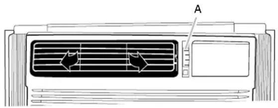
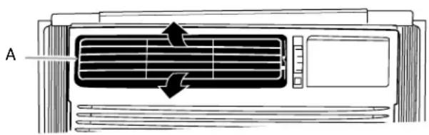
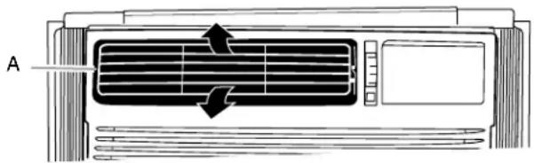
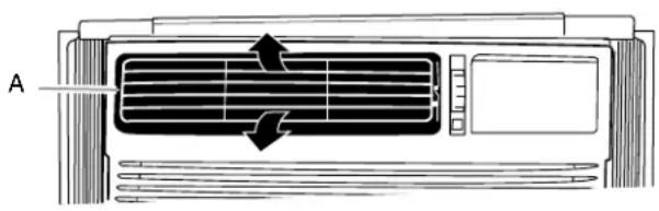
Changing Air Direction
Use wheel to direct the air right or left. Use the whole cartridge to direct air up, down or straight ahead.
natural_image
Diagram of an air conditioner unit with airflow indicators (no text or symbols)A. Wheel
natural_image
Diagram of an air conditioner unit with airflow direction arrows (no text or symbols)A. Cartridge
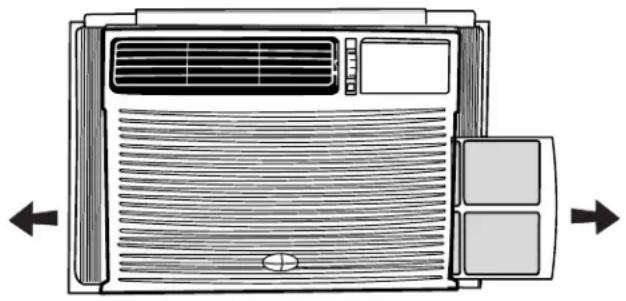
Exhaust Air Vent
■ Pull out the exhaust air vent control to Open the exhaust air vent and draw stale or smoky air from the room.
■ Push in the exhaust air vent control to close the exhaust air vent for maximum continuous cooling.

A. Exhaust air vent control
NOTE: The exhaust air vent control will function only when the Fan Speed control is operating.
Normal Sounds
When your air conditioner is operating normally, you may hear sounds such as:
■ Droplets of water hitting the condenser, causing a pinging or clicking sound. The water droplets help cool the condenser.
■ Air movement from the fan.
■ Clicks from the thermostat cycle.
■ Vibrations or noise due to poor wall or window construction.
■ A high-pitched hum or pulsating noise caused by the modern high-efficiency compressor cycling on and off.
AIR CONDITIONER CARE
Your new air conditioner is designed to give you many years of dependable service. This section tells you how to clean and care for your air conditioner properly. Call your local authorized dealer for an annual checkup. Remember... the cost of this service call is your responsibility.
Cleaning the Air Filter
The air filter is removable for easy cleaning. A clean filter helps remove dust, lint, and other particles from the air and is important for best cooling and operating efficiency. Check the filter every 2 weeks to see whether it needs cleaning.
NOTE: Do not operate the air conditioner without the filter in place.
- Turn off the air conditioner.
- Remove the air filter by sliding the air filter from either side of the front panel.
natural_image
Diagram of an air conditioner unit with airflow arrows indicating airflow direction (no text or symbols)- Use a vacuum cleaner to clean air filter. If the air filter is very dirty, wash it in warm water with a mild detergent. Do not wash the air filter in the dishwasher or use any chemical cleaners. Air dry the air filter completely before replacing to ensure maximum efficiency.
- Replace the air filter by sliding the air filter back in on either side of the front panel.
Cleaning the Front Panel
- Turn off the air conditioner.
- Clean the front panel with a soft, damp cloth.
- Air dry the front panel completely.
Repairing Paint Damage
Check once or twice a year for paint damage. This is very important, especially in areas near oceans or where rust is a problem. If needed, touch up with a good grade enamel paint.
Annual Maintenance
Your air conditioner needs annual maintenance to help ensure steady, top performance throughout the year. Call your local authorized dealer to schedule an annual checkup. The expense of an annual inspection is your responsibility.
TROUBLESHOOTING
Before calling for service, try the suggestions below to see whether you can solve your problem without outside help.
Air conditioner will not operate
WARNING

Electrical Shock Hazard
Plug into a grounded 3 prong outlet.
Do not remove ground prong.
Do not use an adapter.
Do not use an extension cord.
Failure to follow these instructions can result in death, fire, or electrical shock.
■ The power supply cord has tripped (Reset button has popped out). Press and release RESET (listen for click; Reset button will latch and on some devices, a green light will turn on) to resume operation.
■ A household fuse has blown, or circuit breaker has tripped. Replace the fuse or reset the circuit breaker. If the problem continues, call an electrician. See “Electrical Requirements.”
■ The Power button has not been pressed. Press the Power button.
■ The local power has failed. Wait for power to be restored.
■ The power supply cord is unplugged. Plug into grounded 3 prong outlet. See “Electrical Requirements.”
Air conditioner blows fuses or trips circuit breakers
■ Too many appliances are being used on the same circuit. Unplug or relocate appliances that share the same circuit.
■ Time-delay fuse or circuit breaker of the wrong capacity is being used. Replace with a time-delay fuse or circuit breaker of the correct capacity. See “Electrical Requirements.”
■ An extension cord is being used. Do not use an extension cord with this or any other appliance.
■ You are trying to restart the air conditioner too soon after turning off the air conditioner. Wait at least 3 minutes after turning off the air conditioner before trying to restart the air conditioner.
Air conditioner power supply cord trips (Reset button pops out)
■ Disturbances in your electrical current can trip (Reset button will pop out) the power supply cord. Press and release RESET (listen for click; Reset button will latch and on some devices, a green light will turn on) to resume operation.
■ Electrical overloading, overheating, cord pinching or aging can trip (Reset button will pop out) the power supply cord. After correcting the problem, press and release RESET (listen for click; Reset button will latch and on some devices, a green light will turn on) to resume operation.
NOTE: A damaged power supply cord must be replaced with a new power supply cord obtained from the product manufacturer and must not be repaired.
Air conditioner seems to run too much
The current air conditioner replaced an older model. The use of more efficient components may cause the air conditioner to run longer than an older model, but the total energy consumption will be less. Newer air conditioners do not emit the "blast" of cold air you may be accustomed to from older air conditioners, but this is not an indication of lesser cooling capacity or efficiency. Refer to the efficiency rating (EER) and capacity rating (in Btu/h) marked on the air conditioner.
■ The air conditioner is in a heavily occupied room, or heat-producing appliances are in use in the room. Use exhaust vent fans while cooking or bathing and try not to use heat-producing appliances during the hottest part of the day. A higher capacity air conditioner may be required, depending on the size of the room being cooled.
Air conditioner cycles on and off too much or does not cool/heat room in cooling/heating mode
■ The air conditioner is not properly sized for your room. Check the cooling capabilities of your room air conditioner. Room air conditioners are not designed to cool multiple rooms.
■ The filter is dirty or obstructed by debris. Clean the filter.
■ The inside evaporator and outside condenser coils are dirty or obstructed by debris. See "Annual Maintenance."
There is excessive heat or moisture (open container cooking, showers, etc.) in the room. Use a fan to exhaust heat or moisture from the room. Try not to use heat-producing appliances during the hottest part of the day.
■ The louvers are blocked. Install the air conditioner in a location where the louvers are free from curtains, blinds, furniture, etc.
■ The outside temperature is below 65^ F ( 18^ C). Do not try to operate your air conditioner in the cooling mode when the outside temperature is below 65^ F ( 18^ C).
■ The temperature of the room you are trying to cool is extremely hot. Allow extra time for the air conditioner to cool off a very hot room.
■ Windows or doors to the outside are open. Close all windows and doors.
■ The Exhaust control is set to Open. Push the Exhaust control Closed for maximum cooling.
■ The Temp control is not at a cool enough setting. Adjust the Temp control to a cooler setting by pressing the minus button to reduce the temperature. Set the Fan Speed control to the highest setting.
■ The air conditioner in the heating mode has insufficient Btu/h for the heating requirements of the room. Do not use the air conditioner as a primary source of heat.
Water drips from cabinet into your house
■ The air conditioner is not properly leveled. The air conditioner should slope slightly downward toward the outside. Level the air conditioner to provide a downward slope toward the outside to ensure proper drainage. See the Installation Instructions.
NOTE: Do not drill a hole in the bottom of the metal base and condensate pan.
ASSISTANCE OR SERVICE
Before calling for assistance or service, please check
“Troubleshooting.” It may save you the cost of a service call. If you still need help, follow the instructions below.
When calling, please know the purchase date and the complete model and serial number of your appliance. This information will help us to better respond to your request.
If you need replacement parts
If you need to order replacement parts, we recommend that you use only factory-specified replacement parts. Factory-specified replacement parts will fit right and work right because they are made with the same precision used to build every new appliance.
To locate factory-specified replacement parts in your area, call your nearest designated service center.
Please record your model's information.
Whenever you call to request service on your appliance, you need to know your complete model number and serial number.
You can find this information on the model and serial number label. See “Electrical Requirements” for the location of the model and serial number label.
Please record the model and serial number information below.
Also, record the purchase date of your appliance and the store's name, address, and telephone number.
Model Number
Serial Number ____
Purchase Date
Store Name ____
Store Address ____
Store Phone
Keep this book and the sales slip together for future reference.
In the U.S.A.
Call Customer Service toll free: 1-877-465-3566 or visit our website at www.whirlpool.com.
Our consultants provide assistance with:
■ Features and specifications on our appliances.
■ Installation information.
■ Use and maintenance procedures.
■ Repair parts sales.
■ Referrals to repair parts distributors and service companies. Designated service technicians are trained to fulfill the product warranty and provide after-warranty service, anywhere in the United States.
For further assistance
If you need further assistance, you can write with any questions or concerns to:
Hisense USA Inc.
Customer Service
105 Satellite Blvd. NW, Suite A
Suwanee, GA 30024
Please include a daytime phone number in your correspondence.
In Canada
Call Customer Service toll free: 1-800-360-2742, or visit our website at www.whirlpool.com.
Our consultants provide assistance with:
■ Features and specifications on our appliances.
■ Use and maintenance procedures.
■ Repair parts sales.
■ Referrals to repair parts distributors and service companies. Designated service technicians are trained to fulfill the product warranty and provide after-warranty service, anywhere in Canada.
For further assistance
If you need further assistance, you can write with any questions or concerns to:
Hisense USA Inc.
Customer Service
105 Satellite Blvd. NW, Suite A
Suwanee, GA 30024
U.S.A.
Please include a daytime phone number in your correspondence.
SEGURIDAD DEL ACONDICIONADOR DE AIRE
A. Sello de espuma
B. Cortinas laterales (2)
C. Pernos de 1½" X ¼" (4)
D. Tuercas de ¼" (4)
E. Tornillos de ¼" (23)
F. Tornillos de 3/4" (10)
G. Juntas (10)
natural_image
Line drawing of an air conditioner unit with ventilation grilles and a labeled component (A), no text or symbols present.National Fire Protection Association
One Batterymarch Park
Quincy, MÁ 02269
natural_image
Technical diagram of a heat exchanger or cooling unit with labeled component A (no text or symbols present)natural_image
Line drawing of a computer rack unit with ventilation slots and cable, labeled A (no text or symbols on the diagram itself)A. Manija
natural_image
Technical line drawing of a modular air duct or enclosure unit with ventilation grilles and mounting brackets (no text or symbols)A. Tornillos de 1/4"
B. Ranura superior
natural_image
Line drawing of a hand holding a tool interacting with a vertical panel or panel (no text or symbols present)natural_image
Technical line drawing of a structural support frame with vertical and diagonal beams (no text or symbols)natural_image
Line drawing of two hands holding a curved object inside a transparent container (no text or symbols)natural_image
Line drawing of a cabinet with an inset showing a detailed L-shaped structure (no text or symbols)natural_image
Technical line drawing of a structural support frame with mounting brackets and supports (no text or symbols)natural_image
Line drawing of a rectangular cabinet or enclosure with a label pointing to the top face (no text or symbols on the diagram itself)A. Marco
natural_image
Line drawing of a cabinet with a labeled component 'A' pointing to the interior (no text or symbols on the cabinet itself)A. Nivel
natural_image
Diagram of a microwave oven with labeled component A, showing internal wiring and housing (no text or symbols beyond label)natural_image
Line drawing of a portable air conditioner unit with ventilation grilles and cooling fins (no text or symbols)natural_image
Diagram of an air conditioner unit with airflow indicators (no text or symbols)A. Rueda
natural_image
Diagram of a car air conditioner unit with airflow arrows indicating airflow direction (no text or symbols)A. Cartucho
natural_image
Diagram of an air conditioner unit with airflow arrows indicating airflow direction (no text or symbols)105 Satellite Blvd. NW, Suite A
Suwanee, GA 30024
A. Joint en mousse
F. Vs de 3/4" (10)
natural_image
Line drawing of a portable air conditioner unit with ventilation grilles and labeled component A (no text or symbols beyond label)A. Persiennes
National Fire Protection Association
One Batterymarch Park
Quincy, MÁ 02269
natural_image
Diagram of a heat exchanger or cooling unit with labeled component A, showing internal structure and wiring (no text or symbols beyond label)A. Emplacements des vis
natural_image
Line drawing of a server rack unit with ventilation slots and cable, labeled A (no text or symbols on the diagram itself)A. Poignée
natural_image
Technical line drawing of a modular device with labeled components A and B (no text or symbols beyond labels)natural_image
Line drawing of a hand holding a tool interacting with a vertical panel or door (no text or symbols present)natural_image
Pure technical line drawing of a mechanical structure without any text, numbers, or symbolsnatural_image
Line drawing of hands holding a curved object inside a transparent container (no text or symbols)natural_image
Line drawing of a cabinet with an inset showing a detailed L-shaped structure (no text or symbols)natural_image
Technical line drawing of a mechanical assembly with mounting brackets and structural supports (no text or symbols)natural_image
Line drawing of a rectangular cabinet or enclosure with a label pointing to the top face (no text or symbols on the diagram itself)A. Garniture
natural_image
Diagram of a cabinet or enclosure with three buttons and a label 'A' pointing to one (no text or symbols on the diagram itself)A. Niveau
natural_image
Diagram of a microwave oven with labeled component A, showing internal structure and wiring (no text or symbols beyond label)natural_image
Line drawing of a portable air conditioner unit with ventilation grilles and cooling fins (no text or symbols)Power (alimentation)
natural_image
Diagram of an air conditioner unit with airflow indicators (no text or symbols)A. Roue
natural_image
Diagram of an air conditioner unit with airflow arrows indicating airflow direction (no text or symbols)A. Cartouche
Ventilation
natural_image
Diagram of an air conditioner unit with airflow arrows indicating airflow direction (no text or symbols)ASSISTANCE OU SERVICE
105 Satellite Blvd. NW, Suite A
Suwanee, GA 30024
105 Satellite Blvd. NW, Suite A
Suwanee, GA 30024
États-Unis