Kühl YS12M33 - Air Conditioning Friedrich - Free user manual and instructions
Find the device manual for free Kühl YS12M33 Friedrich in PDF.

User questions about Kühl YS12M33 Friedrich
0 question about this device. Answer the ones you know or ask your own.
Ask a new question about this device
Download the instructions for your Air Conditioning in PDF format for free! Find your manual Kühl YS12M33 - Friedrich and take your electronic device back in hand. On this page are published all the documents necessary for the use of your device. Kühl YS12M33 by Friedrich.
USER MANUAL Kühl YS12M33 Friedrich
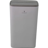
Room Air Conditioners
natural_image
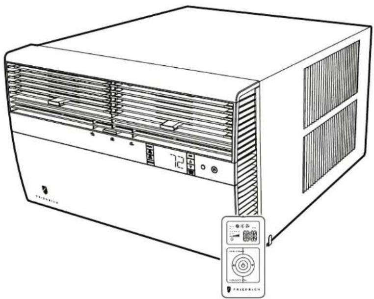
Line drawing of a white air conditioner unit with ventilation grilles and control panel (no text or symbols)Standard Chassis Models
| Kühl | 115-Volt: SS08M10, SS10M10, SS12M10, SS14M10208-230-Volt: SS12M30, SS15M30, SM18M30, SM21M30SM24M30, SL28M30, SL36M30 |
| Kühl+Electric Heat | 115-Volt: YS10M10208-230-Volt: ES12M33, ES15M33, YS12M33, EM18M34,YM18M34, EM24M34, EL36M35, YL24M35 |
| Kühl+Heat Pump |
THANK YOU!
Thank you for your decision to purchase the Friedrich High Efficiency Air Conditioner. Your new Friedrich has been carefully engineered and manufactured to give you many years of dependable, efficient operation, maintaining a comfortable temperature and humidity level. Many extra features have been built into your unit to assure quiet operation, the greatest circulation of cool, dry air, and the most economic operation.
text_image
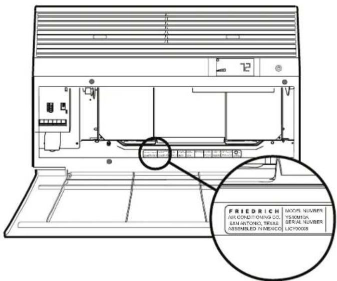
FRIEDRICH AIR CONDITIONING CO. SAN ANTONIO, TEXAS ASSEMBLED IN MEXICO MODEL NUMBER YS10M0A SERIAL NUMBER LICY0008Register your air conditioner
Model information can be found on the name plate behind the front cover.
Please complete and mail the owner registration card furnished with this product, or register online at www.friedrich.com (USA only). For your future convenience, record the model information here.
MODEL NUMBER
SERIAL NUMBER
PURCHASE DATE
Table of Contents
Safety Precautions 4
Unpacking Instructions....5
WARNING: Before Operating Your Unit ....6
Standard Filter Cleaning / Installation Instructions....7
Premium Carbon Filter Installation Instructions....8
Control Panel Operation 10
Add a Remote Thermostat....14
Remote Thermostat Selection 14
Remote Control Operation 15
Remote Effectiveness 15
Airflow Selection and Adjustment....17
Installation Instructions 18
Standard Window Installation 20
Cord Routing Change 30
Through-the-Wall Installation....32
Programmable Thermostat 36
Final Inspection & Start-up Checklist....38
Routine Maintenance 39
Service and Assistance 39
Available Accessories 39
Troubleshooting Tips....40
Addendum 1 42
Safety Precautions
Your safety and the safety of others are very important.
We have provided many important safety messages in this manual and on your appliance. Always read and obey all safety messages.

This is a safety Alert symbol.
This symbol alerts you to potential hazards that can kill or hurt you and others.
All safety messages will follow the safety alert symbol with the word "WARNING"
or "CAUTION". These words mean:
WARNING
CAUTION
Indicates a hazard which, if not avoided, can result in severe personal injury or death and damage to product or other property.
Indicates a hazard which, if not avoided, can result in personal injury and damage to product or other property.
All safety messages will tell you what the potential hazard is, tell you how to reduce the chance of injury, and tell you what will happen if the instructions are not followed.
NOTICE
Indicates property damage can occur if instructions are not followed.
WARNING

Refrigeration system under high pressure
Do not puncture, heat, expose to flame or incinerate.
Only certified refrigeration technicians should service this equipment.
R410A systems operate at higher pressures than R22 equipment. Appropriate safe service and handling practices must be used.
Only use gauge sets designed for use with R410A. Do not use standard R22 gauge sets.
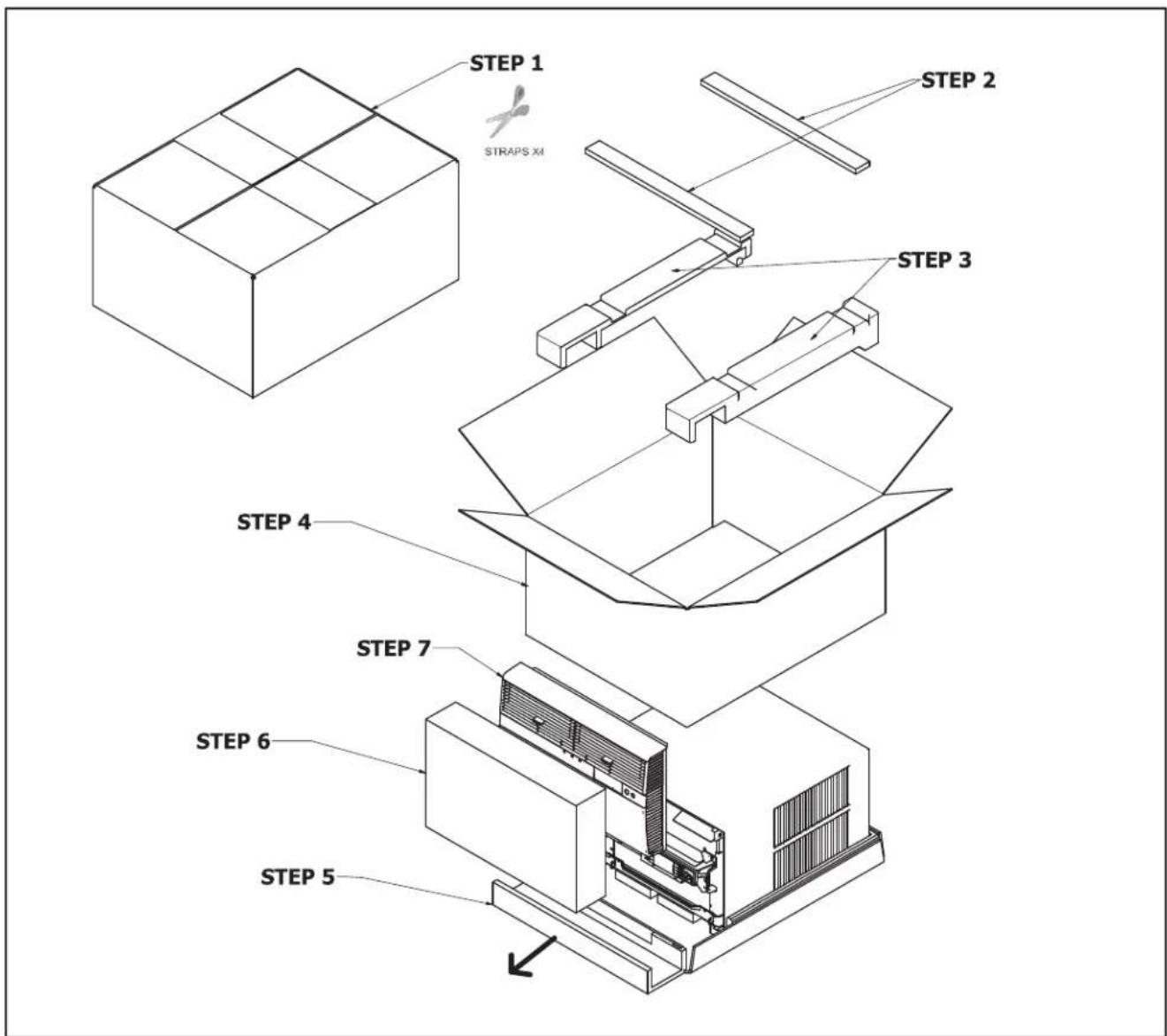
Unpacking Instructions
STEP 1. Cut all 4 packing straps.
STEP 2. Remove wooden shipping bar dividers.
STEP 3. Remove top foam pads.
STEP 4. Slowly remove outer box, careful not to loosen decorative front.
STEP 5. Slide the foam front support forward
STEP 6. Carefully lift decorative front box from foam front support
STEP 7. Remove decorative front and set safely aside
text_image
STEP 1 STRAPS XM STEP 2 STEP 3 STEP 4 STEP 7 STEP 6 STEP 5WARNING: Before Operating Your Unit
| WARNING | |
 | Electrical Shock HazardMake sure your electrical receptacle has the same configuration as your air conditioner's plug. If different, consult a Licensed Electrician.Do not use plug adapters.Do not use an extension cord.Do not remove ground prong.Always plug into a grounded 3 prong outlet.Failure to follow these instructions can result in death, fire, or electrical shock. |
Make sure the wiring is adequate for your unit.
If you have fuses, they should be of the time delay type. Before you install or relocate this unit, be sure that the amperage rating of the circuit breaker or time delay fuse does not exceed the amp rating listed in Table 1.
DO NOT use an extension cord.
The cord provided will carry the proper amount of electrical power to the unit; an extension cord may not.
Make sure that the receptacle is compatible with the air conditioner cord plug provided.
Proper grounding must be maintained at all times. Two prong receptacles must be replaced with a grounded receptacle by a certified electrician. The grounded receptacle should meet all national and local codes and ordinances. You must use the three prong plug furnished with the air conditioner. Under no circumstances should you remove the ground prong from the plug.
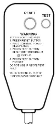
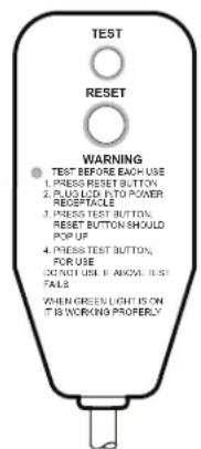
Test the power cord
All Friedrich room air conditioners are shipped from the factory with a Leakage Current Detection Interrupter (LCDI) equipped power cord. The LCDI device on the end of the cord meets the UL and NEC requirements for cord connected air conditioners.
To test your power supply cord:
- Plug power supply cord into a grounded 3 prong outlet.
- Press RESET (See Figure 1).
- Press TEST, listen for click; the RESET button trips and pops out.
- Press and release RESET (Listen for click; RESET button latches and remains in). The power cord is ready for use.
NOTICE
Do not use the LCDI device as an ON/OFF switch.
Failure to adhere to this precaution may cause premature equipment malfunction.
Once plugged in, the unit will operate normally without the need to reset the LCDI device. If the LCDI device fails to trip when tested or if the power supply cord is damaged, it must be replaced with a new power supply cord from the manufacturer. Contact our Technical Assistance Line at (800) 541-6645. To expedite service, please have your model number available.
| Table 1. | ||||
| MODEL | CIRCUIT RATING OR TIME DELAY FUSE | REQUIRED WALL RECEPTACLE | ||
| AMP VOLT | NEMA NO. | |||
| SS08M10, SS10M10, SS12M10, SS14M10, YS10M10 | 15 125 | 5-15R | ||
| SS12M30, SS15M30, SM18M30, SM21M30 | 15 250 | 6-15R | ||
| SM24M30, SL28M30, ES12M33, ES15M33, YS12M33 | 20 250 | 6-20R | ||
| SL36M30, EM18M34, EM24M34, EL36M35, YM18M34, YL24M35 | 30 250 | 6-30R | ||
Figure 1
text_image
RESET TEST WARNING 1. PRESS RESET BUTTON 2. PUSH LED INTO POWER READ PAGLE 3. PRESS TEST BUTTON PRESS BUTTON SCHEDULE 3 4. POP UP 5. PRESS TEST BUTTON FOR USE DO NOT USE IF ABOVE TEST FAILS WHEN GREENLIGHT IS ON IF IS WORKING PRIORLY15/20A LCDI Device
text_image
TEST RESET WARNING 1. PRESS RESET BUTTON 2. PLUG LICK INTO POWER RECEPTACLE 3. PRESS TEST BUTTON RESET BUTTON SHOULD POP UP 4. PRESS TEST BUTTON FOR USE DO NOT USE IF ABOVE TEST FALS WHEN GREEN LIGHT IS ON IT IS WORKING PROPERLY30A LCDI Device
FRR001
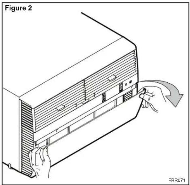
Standard Filter Cleaning / Installation Instructions
STEP 1. Swing the door open and remove the filter by grasping the filter grip and pushing the filter holder upward and outward.
text_image
Figure 2 FRR071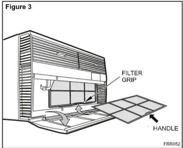
text_image
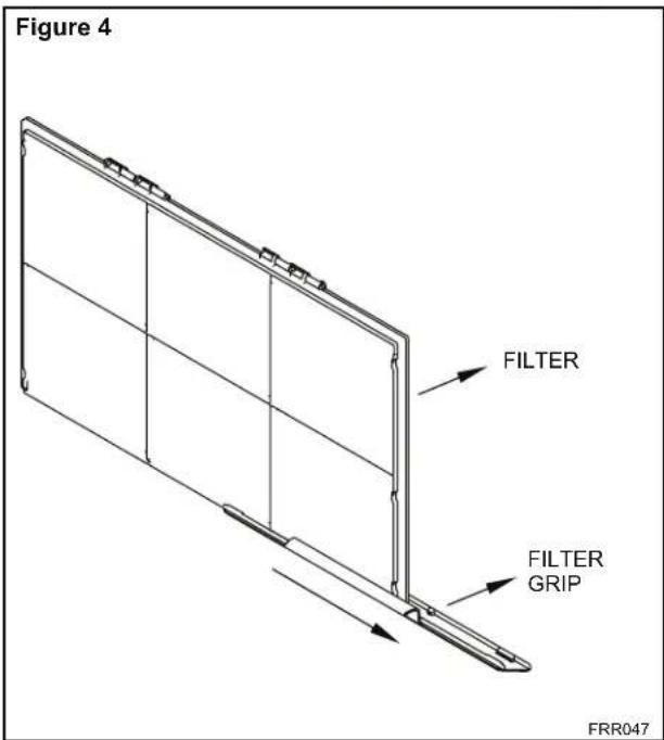
Figure 3 FILTER GRIP HANDLE FRR052STEP 2. Slide the filter grip out from the filter as shown in Figure 4.
NOTE: Make sure the front frame with the mesh filter is facing you.
text_image
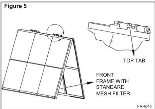
Figure 4 FILTER FILTER GRIP FRR047STEP 3. Swing the front frame open. Clean the front frame by washing the dirt from the filter. Use a mild soap solution if necessary. Allow filter to dry.
text_image
Figure 5 TOP TAB FRONT FRAME WITH STANDARD MESH FILTER FRR048STEP 4. Install the filter grip back into the filter by sliding it into the filter.
NOTE: The filter handle slides into the frame in only one direction. If the tab in the frame stops the handle from sliding in, slide the handle from the other direction. Do not force the handle into the frame.
STEP 5. Install the filter back into the unit. Follow the Instructions on the inside of the front door.
Premium Carbon Filter Installation Instructions
STEP 1. Remove the filter from the unit as per the instructions on the inside of the filter door.
STEP 2. Hold the filter at the top and slide the filter grip out as shown in Figure 4.
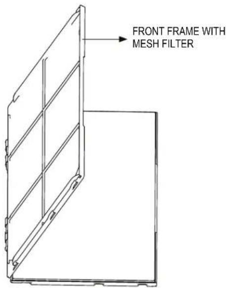
STEP 3. If you already have a carbon filter installed remove the dirty filter by laying the filter down and swinging open the front frame as shown in Figure 6.
NOTE: Make sure the frame with the mesh is facing towards you.
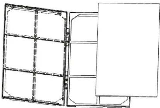
STEP 4. Place the new carbon filter on the top of the back filter frame. The carbon filter has been cut to the correct dimension and should fit within the frame as shown in figure 7
NOTE: The carbon filter is not a re-usable filter, and needs to be replaced every three months for optimum efficiency.
STEP 5. Slide the filter handle back on to hold the frames together and slide the assembly into the unit as per the instructions on the door.
NOTE: The filter handle slides into the frame in only one direction. If the tab in the frame stops the handle from sliding in, slide the handle from the other direction. Do not force the handle into the frame.
Figure 6
text_image
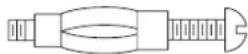
FRONT FRAME WITH MESH FILTERFigure 7
natural_image
Technical line drawing of a dual-panel storage unit with no text or symbolsFRR051FRR050
THIS PAGE INTENTIONALLY LEFT BLANK
Control Panel Operation
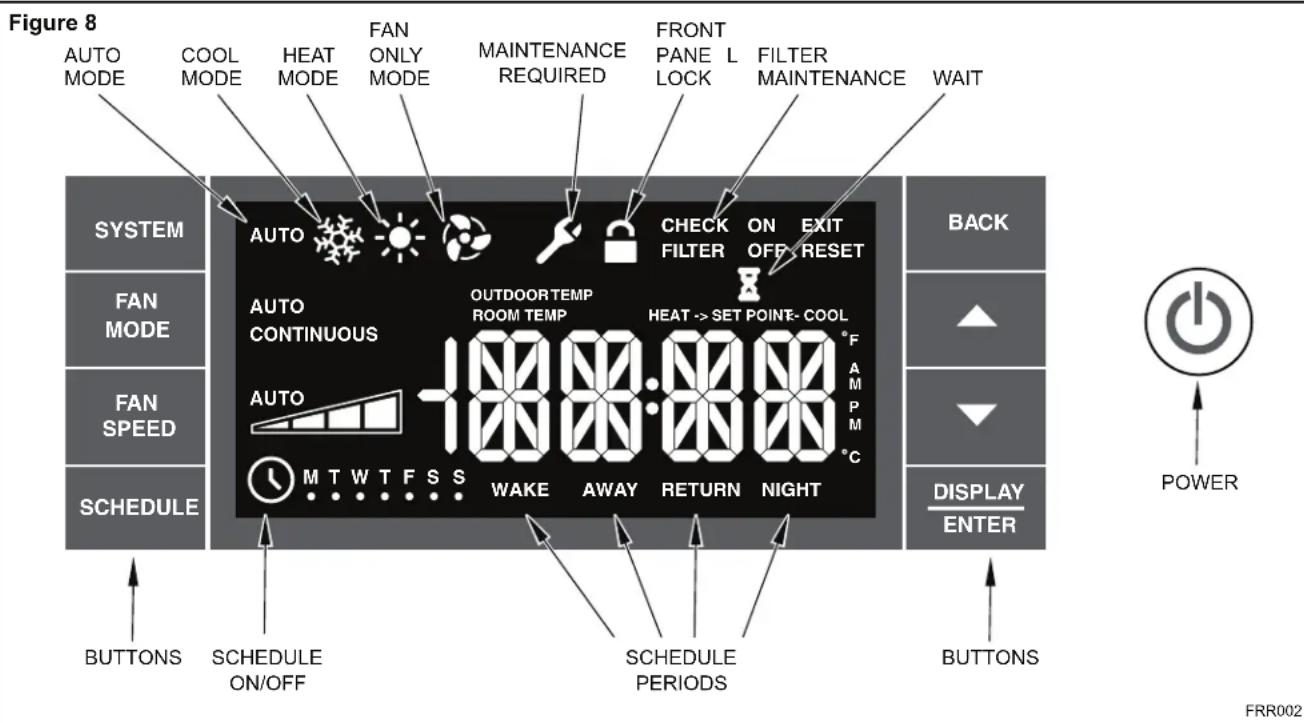
Let's check out how to control your air conditioner. On the control panel, just to the left of the POWER is a liquid crystal display (LCD). All of the control panel function buttons and mode icons can be viewed in Figure 8.
Power On – Press the ⏻ button to turn on the air conditioner. The power button will illuminate to indicate the power is on. The backlight on the power switch will automatically dim to 20% intensity after 15 seconds of inactivity. The remote control can also be used to turn power ON / OFF (See Remote Control).
Display – The display is a high efficiency LCD with a built-in white back light. The back light has an automatic two (2) step dim function. After 15 seconds of inactivity, the display dims to 20% intensity. After an additional 120 seconds, the display switches off. Touching buttons will automatically bring the display to full brightness.
There are four control push buttons on each side of the display.
SYSTEM Button – Allows the user to sequentially select, AUTO Cool *, HEAT and FAN ONLY operation. Press the button and the display advances to the next mode. A new icon appears. At the same time, the mode displays for two (2) seconds, then returns the display to the temperature set point for modes other than FAN. Note that when the heating function is not available, the system will automatically skip the HEAT and AUTO.
NOTE: After the compressor stops the fan will continue to operate for 30 seconds.
FAN MODE Button – Selects between automatic AUTO or CONTINUOUS operation. In the AUTO, the fan only turns on and off when the compressor operates or the heat function is enabled.
In the FAN ONLY Mode, AUTO is not available. The display indicates CONTINUOUS. In the CONTINUOUS speed is determined by your selection on the AUTO SPEED.
FAN SPEED Button – Used to sequentially select between fan speeds. Depending on your model, you can select between LOW, MED, HIGH, and MAX and AUTO. Max setting not on SL, EL, YL or cool plus models). When the FAN SPEED button is pressed, the fan speed is temporarily displayed in the display window, plus a fan speed icon (triangle) changes to indicate the new speed level. When auto is selected, fan speed automatically varies depending on the set temperature on the control panel and the actual room temperature. Let me explain. Say for example you're working in your garage and you need to open the big door for several minutes. The air conditioner will sense a wide difference between the set temperature and the actual room temperature when this occurs the system fan speed increases to MAX. The fan speed decreases (in step) as the temperature difference decreases. When the set point temperature is reached the FAN speed returns to the original setting.
SCHEDULE Button – The 📋 button turns the schedule function on and off. The current day of the week is indicated as a dot underneath the day symbol. Pressing the 📋 button a second time turns the schedule function off. The schedule function comes preprogrammed with recommended energy savings values (Addendum 1). The values may be changed through the schedule program function (See Programmable Thermostat).
UP and DOWN arrows – Pressing either ▲(UP) or ▼(DOWN) button changes the desired room temperature. The factory preset lower and upper limits are 60° F (16° C) and 99° F (37° C). These buttons are also used to navigate between function options when using the User Menu or Maintenance Mode.
BACK Button – This button is used after a menu item has been selected. It takes the user back to the previous menu level.
DISPLAY/ENTER Button – This button is used in conjunction with User menu and Maintenance Mode operation to select items. This button may also be used alternately to display the ROOM TEMPERATURE and TIME. If the display is left inactive for 10 seconds it will reset to the TEMPERATURE SET POINT.
Alerts – The control system has five (5) customer alerts.
text_image
Figure 8 AUTO MODE COOL MODE HEAT MODE FAN ONLY MODE MAINTENANCE REQUIRED FRONT PANEL LOCK FILTER MAINTENANCE WAIT SYSTEM AUTO CHECK ON EXIT FILTER OFF RESET AUTO CONTINUOUS OUTDOORTEMP ROOM TEMP HEAT -> SET POINT- COOL AUTO M T W T F S S WAKE AWAY RETURN NIGHT SCHEDULE ON/OFF SCHEDULE PERIODS BACK FAN MODE FAN SPEED SCHEDULE DISPLAY ENTER BUTTONS SCHEDULE ON/OFF SCHEDULE PERIODS BUTTONS POWER FRR002CHECK FILTER – When the filter needs to be checked, an icon appears on screen. The word “RESET” acts next to the .nottu PACK. The CHECK FILTER alert is issued when the fan run time is greater than 500 hours. This alert may be reset by the user (Refer to Special Functions, Filter Reset).
Maintenance Required – When maintenance is required, a service icon 📁 appears on screen. This icon will not be dismissed until maintenance has been performed. If the service icon 📁 flashes, maintenance is required and must only be performed by qualified service personnel. When the icon 📁 is on standby the system has sensed an abnormal condition. For example: The air in/out louvres may be blocked. Once proper air flow is established the service icon 📁 goes away.
Wait – The WAIT icon 📁 illuminates when the compressor lockout is active. Whenever the compressor shuts off, system pressures must be allowed to equalize. At this time, an internal timer begins a count-down from up to 240 seconds. If a demand for heat or cool occurs during this count-down the WAIT icon 📁 displays letting you know that the compressor will not operate until the count-down has completed. This timer prevents damage to the unit if it tries to start too quickly after it stops running. Normally the WAIT icon 📁 is off. Once the timer has cleared, the air conditioner will heat or cool based on the temperature setting. Electric heat is not affected by this timer.
Protection Alert (Freeze) – If the room freeze protection is active, the display indicates this by showing Room Freeze Protection "FRZ". Once the condition is satisfied, the "FRZ" display is removed. If the room temperature is less than 40^ F ( 4^ C), and the air conditioner is equipped with electric heat, the room freeze protection will activate. The air conditioner will run high fan and electric heat until the room temperature reaches 46^ F ( 8^ C). Pressing the BACK button delays the freeze protection function for five (5) minutes.
Low Battery – When the battery is low a warning display BATT will be inserted before other messages such as "COOL". If the Low Battery BATT alert is on, the battery in the control unit must be changed. Refer to the changing the battery procedure. Once the battery is changed, the alert message will go off. Refer to Troubleshooting Tips. Under normal conditions the battery life should be greater than 7 years.
Special Functions
Panel Lock 📄 – The front panel push buttons can be locked to prevent inadvertent operation. To lock the front panel, press and hold the 📋+ 📋+ 📋+ 📋+ 📋+ 📋+ 📋+ 📋+ 📋+ 📋+ 📋+ 📋+ 📋+ 📋+ 📋+ 📋+ 📋+ 📋+ 📋+ 📋+ 📋+ 📋+ 📋+ 📋+ 📋+ 📋 + 📋 + 📋 + 📋 + 📋 + 📋 + 📋 + 📋 + 📋 + 📋 + 📋 + 📋 + 📋 + 📋 + 📋 + 📋 + 📋 + 📋 + 📋 + 📋 + 📋 + 📋 + 📋 + 📋 + 📋 + 📋
Filter Reset – If the CHECK FILTER icon displays, the timer may be reset by pressing and holding the BACK button for three (3) seconds. A beep indicates the CHECK FILTER system timer was reset and the CHECK FILTER and the word " RESET" will no longer be visible.
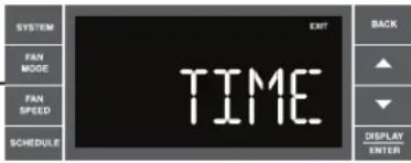
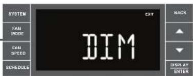
User Menu Functions – The User Menu Functions allows you to change the following selections: Set TIME, 12/24 Hour Clock Format, BEEP ON / OFF, DIM ON / OFF, Emergency Heat (EMHT) ON / OFF, Auto BAND Adjust, F/C Select, FRZ ON / OFF, the Automatic Temperature Sensing Feature and Temp Offset.
To enter the User Menu, press and hold DISPLAY ENTER for 3 seconds, the TIME selection appears. Use the ▲ (UP) or ▼ (DOWN) buttons to scroll through the User Menu. Press the DISPLAY ENTER button to enter the displayed function. If left inactive for 15 minutes the User Menu display will no longer be visible and it returns to normal operation mode display. To manually exit the User Menu, press the BACK button.
text_image
SYSTEM FAN MODE FAN SPEED SCHEDULE EXIT TIME BACK ▲ ▼ DISPLAY ENTERThe hour digits flash first. The user presses the ▲ or ▼ to change the hours. To change AM-PM, the hours must be advanced 12 hours. Press the DEPLAY ENTER key to change to the minutes. To exit the selection process, user presses the BACK key which will go to the time screen.

The minutes digits flash. The user presses the ▲ or ▼ to change the minutes. Press the DEFRAT LIMEE key to change the days. To exit the selection process, the user presses the BACK key which will go to the time screen.

The dot underneath the days of the week begins to blink to indicate which day it is. If the user has not set the date before, the dot starts on Monday. If the user is making a correction to previously set information the dot appears under whichever day the unit thinks it is. The user can press ▲ or ▼ to move the dot left or right (respectively) along the week. The user presses 📄 to loop back to the hours setting. To exit the selection process, the user presses the BACK key which will go to the time screen.

Tuesday has been selected. The user presses 📄 to loop back to the hours setting. To exit the selection process and accept the changes, the user presses the BACK key which will go to the time screen.
FRR062
Time Setting – When in the User Menu, on the Control Panel, use the ▲(UP) and ▼(DOWN) to select TIME. Push ENTER, the hours segment flashes. Use the ▲(UP) and ▼(DOWN) to set the hour, then push ENTER. The minutes segment flashes. Use the ▲(UP) and ▼(DOWN) to set the minutes, then push ENTER.
NOTE: If the AM or PM indicator is incorrect, push ▲ (UP) or ▼ (DOWN) until the hours segment flashes, use the ▲ (UP) or ▼ (DOWN) to advance the hour segment 12 hours, then push ▲ (UP) or ▼ (DOWN). The day of the week displays. Use the ▲ (UP) or ▼ (DOWN) to select the current day. Press the BACK key to save and go back to the TIME screen. Press ▲ (UP) to go to the next menu 1224.
NOTE: Pressing the BACK button again will exit the user menu function mode. Or simply leave the control inactive for 15 seconds and the control will return back to normal operation.
text_image
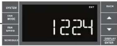
SYSTEM FAN MODE FAN SPEED SCHEDULE 1224 OUT BACK DISPLAY ENTERUser presses ▲ or ▼ to toggle the format between 12HR and 24HR display. To exit the selection process and accept the change, press the BACK key.
FRR063
Clock Type – You may select between a 12 hr and 24 hr clock. When 1224 is displayed press the ☑ key then press ▶ P) or (□) to toggle between 12 hr and 24 hr clock. To accept the change, press the BACK key to return to the 1224 screen. Press the (□) to go to the next menu BEEP.

text_image
SYSTEM FAN MODE FAN SPEED SCHEDULE BEEP BACK DISPLAY ENTERUser presses ▲ or ▼ to toggle between Beep On and Beep Off. Press the BACK key to accept the change and exit the selection process.
FRR064
Audible Alerts – You can select to have the control beep when entering menus. When BEEP is displayed press the ▲ (DOWN) key then press ▲ (UP) or ▼ (DOWN) to toggle between ON and OFF. To accept the change, press the ▲ (BACK) key to return to the BEEP screen. Press the ▲ (UP) to go to the next menu EMHT on Kühl+ models or F C for Kühl models.
text_image
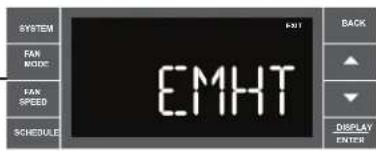
SYSTEM FAN MODE FAN SPEED SCHEDULE EMHT BACK DISPLAY ENTERUser presses ▲ or ▼ to toggle between Emergency Heat On and Emergency Heat Off. Press the BACK key to accept the change and exit the selection process.
FRR065
Emergency Heat - The Kühl+ heat pump models (YS, YM, YL) have a special feature that is designed to keep the unit providing heat. When EMHT is displayed press the DISPLAY key then press 📄P) or ▼(DOWN) to toggle between ON and OFF.
To accept the change, press the BACK key to return to the EMHT screen. Press the ▲ (UP) to go to the next menu BAND.
In the unlikely event of a compressor failure, the heat pump unit may be switched to operate in the electric heat mode only until repairs can be made.
text_image
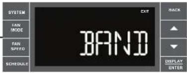
SYSTEM FAN MODE FAN SPEED SCHEDULE EXIT BRAND BACK ▲ ▼ DISPLAY ENTERThe menu allows the user to adjust the minimum spread between the Auto Cool set point and the Auto Heat set point. Press the ▲ or ▼ key to adjust. The adjust range is 3 to 10.
FRR066
Auto Changeover 'Dead Band' – A buffer Zone between heating and cooling in which no conditioning occurs. For Kühl+ models with the auto changeover feature you can select the temperature band between heating and cooling. From the factory the band is set at 3° F (-16° C). The band is adjustable from 3° F (-16° C) to 10° F (-12° C). When BAND is displayed press the □ key then press ▲(UP) or ▼(DOWN) to toggle between 3 and 10. To accept the change, press the □ key to return to the BAND screen. Press the ▲ (UP) to go to the next menu F C.
text_image
SYSTEM FAN MODE FAN SPEED SCHEDULE DIM EXIT BACK ▲ ▼ DISPLAY ENTERUser presses ▲ or ▼ to select between AUTO, DM 20, OFF. Press the BACK key to accept the change and exit the selection process.
The Dim Auto automatically dims the display and then turns it off after a period of time. The Dim 20 setting behavior is similar to AUTO, but prevents the display from turning off. Minimum brightness is 20%. The Dim Off setting forces the display to run at full brightness.
FRR067
text_image
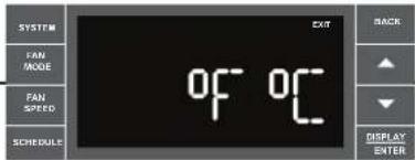
SYSTEM FAN MODE FAN SPEED SCHEDULE OF OF EXIT BACK DISPLAY ENTERUser presses ▲ or ▼ at the same time to toggle between Fahrenheit or Celsius as their temperature unit of choice. Press the BACK key to accept the change and exit the selection process.
FRR068
Fahrenheit / Celsius Selection – You may select between displaying temperature in F or C. When F C is displayed press the ENTER key then press (AP) or (DYN) to toggle between F and C. To accept the change, press the BACK key to return to the F C screen. Press the (UP) to go to the next menu FRZ.
text_image
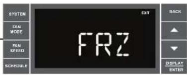
SYSTEM SAN MODE FAN SPEED SCHEDULE FRZ OUT BACK ▲ ▼ DISPLAY ENTERUser presses ▲ or ▼ to select between Freeze Protection On & Freeze Protection Off. Press the BACK key to accept the change and exit the selection process.
FRR069
Freeze Protection - The Kühl+ models have a special feature that is designed to keep the interior space above freezing by energizing the electric heater anytime the indoor room temperature falls to 40^ (4°C). With the freeze protection feature turned on, when the unit senses the indoor temperature fall to 40^ (4°C) the unit will run the heater and high fan until the space reaches 46^ (8°C). When FRZ is displayed press the key then press (L.P.) or (D.W.N.) to toggle between ON and OFF. To accept the change, press the BACK to return to the FRZ screen. Press the (L.P.) to go to the next menu TO.
text_image
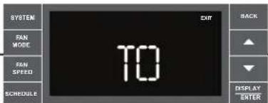
SYSTEM FAN MODE FAN SPEED SCHEDULE TO EXIT BACK DISPLAY ENTERUser presses ▲ or ▼ to increment/decrement the temperature offset (TO) for the room temperature sensor. (Maximum offset = +/- 8 degrees F). Press the BACK key to accept the change and exit the selection process
FRR070
Temperature Offset – In some cases the built in thermostat on the unit may not display the temperature as it is felt in the room. This can be caused by many things including the size of the unit, the heat load on the room or other factors. Friedrich allows you to select the appropriate temperature offset to make the temperature readout as accurate as possible for your application. In many cases the factory 0° F (-18°C) offset will provide an accurate temperature readout. To change the offset follow these instructions. When TO is displayed press the DISPLAY key then press ▲ (UP) or ▼(DOWN) to toggle between 0° F (-18°C) and 8° F (-13°C). In most instances an offset from 0° F (-18°C) to 2° F (-17°C) is all that is necessary. To accept the change, press the ▼(MCK) to return to the TO screen. Press the ▼(LP) to go to the next menu TIME.
You may cycle through the menus using the ▲ (UP) or ▼(OWN) keys to access any of the menus.
text_image
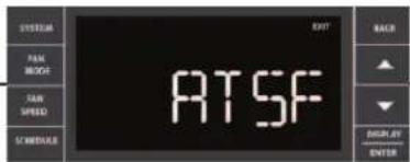
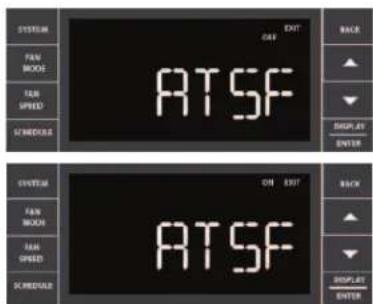
SYSTEM PAM MOCK TAW SPEED SCHEDULE ATT BACK ▲ ▼ DISPLAY ENTER ATSFFRR072
User presses ▲ or ▼ to select between ATSF On or Off. Press the BACK key to accept the change and exit the selection process.
text_image
SYSTEM FAN MODE FAN SPRING SPEEDS OUT OFF ATSF BACK ▲ ▼ DISPLAY ENTER SYSTEM FAN MODE FAN SPRING SPEEDS ON OFF ATSF BACK ▲ ▼ DISPLAY ENTERFRR073
FRR074
Automatic Temperature Sampling Feature - The automatic temperature sampling feature maintains a balanced temperature throughout the room by circulating the air for 30 seconds once every 9 minutes that the unit is not running and set to cooling or heating mode. By circulating the air the unit can detect hot or cold area in the room and operate the unit to cool or warm the room as necessary. This function is only available when the fan mode is set to 'AUTO' and in COOL or HEAT mode. (Heating function only available on Kuhl+ units)
text_image
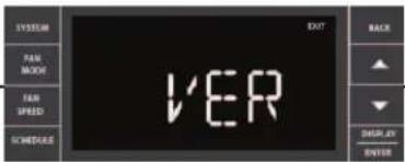
SYSTEM FAM MOOR FAM SPRING SCHEDULES EXIT VER BACK ▲ ▼ DISPLAY ENTERFor display only. No user selectable options.
FRR075

text_image
ITEM FAN MUSIC FAN SPEED ENTER 1 3Firmware Version - When VER is displayed press Display / Enter key. The firmware version is displayed as left digit (Major) and right digit (Minor). This version number should be used along with Model and Serial numbers for service.
FRR076
Add a Remote Thermostat
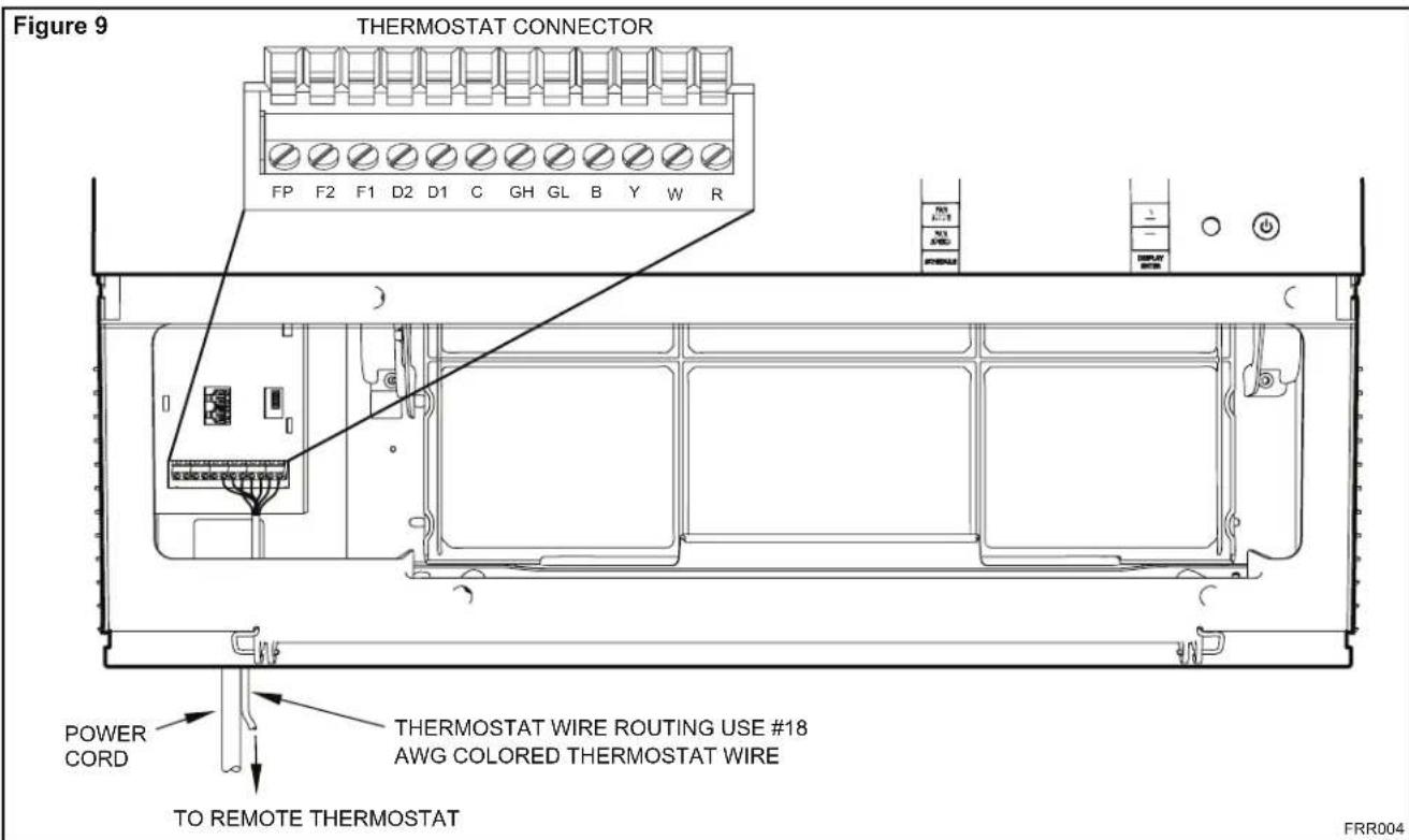
Remote Thermostat – An external thermostat may be added to the air conditioner to provide remote temperature sensing and control. The thermostat interface connector is located on the panel behind the front grille. To enable the remote thermostat operation, remove the jumper
- Changing modes on the remote thermostat will not illuminate the Control Panel LCD.
Remote Thermostat Selection
Friedrich recommends the use of either the RT4 or RT5. The RT4 is a digital display thermostat with single speed fan control. The RT5 features a digital display, two fan speed selection, battery backup and backlight.
text_image
Figure 9 THERMOSTAT CONNECTOR FP F2 F1 D2 D1 C GH GL B Y W R POWER CORD THERMOSTAT WIRE ROUTING USE #18 AWG COLORED THERMOSTAT WIRE TO REMOTE THERMOSTAT FRR004| Table 2 Interface Definitions | |
| Terminal Code | Wire Connection Function |
| C | Common Ground Terminal |
| GH | Call for High Fan |
| GL | Call for Low Fan |
| B | Call for Heat Pump Reversing Valve |
| Y | Call for Compressor |
| W | Call for Heating |
| R | 24V Power from Electronic Control to Wall Thermostat |
between terminals FP & F2 on the terminal block. Connect the thermostat using Figure 9 and Table 2 as a guide.
If you connect an external thermostat, all Control Panel buttons will be disabled with the following exception:
- Maintenance commands (double button press & single button extended press).
- The DEPLAT button for Freeze protection.
- First Button pushed, illuminate the LCD.
Other thermostats may be used as long as they are configured correctly for the unit. For cooling models a single stage cooling thermostat with C, R, G, Y terminals must be used. For electric heat 'E' models a single stage heating and cooling thermostat with C, R, G, Y, W terminals must be used. For heat pump 'Y' models a single stage heating and cooling thermostat with C, R, G, Y, W, B terminals must be used.
| CAUTION | |
 | It is the installer's responsibility to ensure that all control wiring connections are made in accordance with the installation instructions.Improper connection of the thermostat control wiring and/or tampering with the unit's internal wiring can void the equipment warranty.Failure to follow these instructions can result in personal injury and damage to product or other property. |
Remote Control Operation
Remote Control – Refer to Figures 11 and 12 during operation description.
Getting Started – Install two (2) AAA batteries in the battery compartment located on the back of the unit.
Operation - The remote control should be within 25 feet of the air conditioner for operation (Refer to Figure 10 for effectiveness). Press the button to turn the remote on. The remote will automatically power off after 15 seconds if the buttons are not being pressed. The remote must be on to control the unit.
POWER Button – Turns remote and unit on and off.
SYSTEM Button – Allows the user to sequentially select, AUTO Cool HEAT and FAN ONLY operation. When the button is pressed, the display indicates which mode has been selected via a display message. Note that when the heating function is not available, the system will automatically skip the HEAT and AUTO modes.
FAN MODE Button – Selects between automatic (AUTO) or CONTINUOUS operation. In the AUTO mode, the fan only turns on and off when the compressor operates or the heat function is enabled.
NOTE: AUTO is not available in the FAN ONLY Mode, the display indicates CONTINUOUS. In the CONTINUOUS mode, fan speed is determined by your selection on the FAN SPEED button.
FAN SPEED Button – Used to sequentially select new fan speed, plus AUTO operation. When the FAN SPEED button is pressed, the fan speed is temporarily displayed in the display window, plus a fan speed icon (triangle) changes to indicate the new speed level. Fan speed automatically varies depending on the set temperature on the control panel and the actual room temperature. Let me explain. Say for example you're working in your garage and you need to open the big door for several minutes. Since there is a big difference between your set temperature and the actual room temperature the system fan speed increases to MAX. It remains at this speed until the room temperature matches the set temperature.
SCHEDULE Button – The button turns the schedule function on and off. Pressing the button a second time turns the schedule function off. Only the schedule icon will be displayed.
UP and DOWN Arrows – Pressing either the ▲ (UP) or ▼ (DOWN) button changes the desired room temperature. The factory preset lower and upper limits are 60° F (16° C) and 99° F (37° C). These buttons are also used to navigate between function options when using the User Menu or Maintenance Mode.
Remote Effectiveness
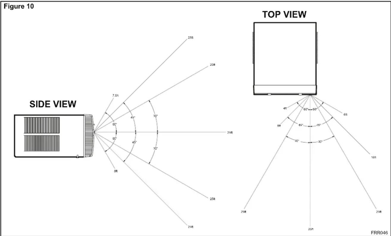
Hand Held Remote – Has an operating range of up to 25 ft. The infrared remote control signal must have a clear path to transmit the command to the air conditioning unit. The remote signal has some ability to "bounce" off of walls and furniture similar to a television remote control. The diagram below shows the typical operating range of the control in a standard room with 8 ft high ceilings.
text_image
Figure 10 SIDE VIEW TOP VIEW 25ft 25ft 7.5ft 40° 30° 60° 45° 30° 8ft 25ft 25ft 60°-60° 6ft 4ft 8ft 45° 45° 30° 30° 16ft 25ft 25ft 25ft FRR046Figure 11

text_image
DISPLAY AUTO AUTO CONTINUOUS AUTO °F°C SYSTEM FAN MODE FAN MODE POWER TEMPERATURE UP TEMPERATURE DOWN SCHEDULE FAN SPEED FAN SPEED FRIEDRICHFRR005
Figure 12
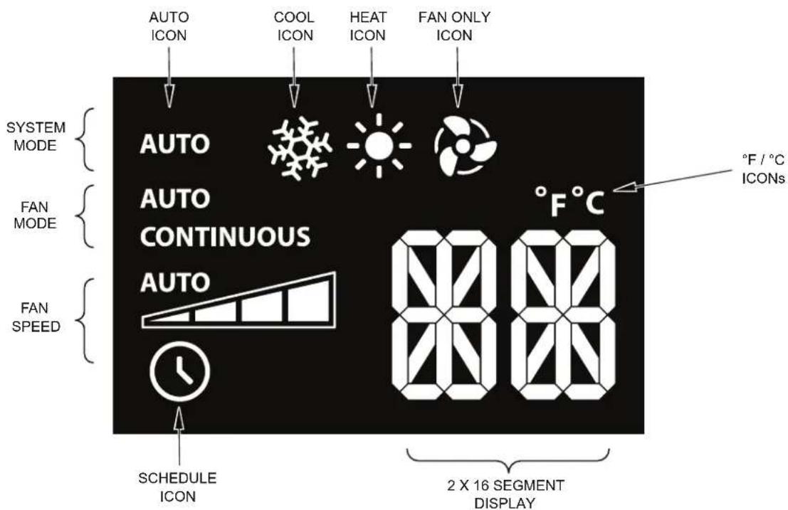
text_image
AUTO ICON COOL ICON HEAT ICON FAN ONLY ICON SYSTEM MODE AUTO AUTO CONTINUOUS AUTO °F / °C ICONs FAN MODE FAN SPEED SCHEDULE ICON 8000 2 X 16 SEGMENT DISPLAYFRR006
Airflow Selection and Adjustment
Air flow direction adjustment
The airflow path may be adjusted to distribute air independently from the left or right side of the discharge opening. Each of the banks of louvers can be directed left, right, up or down in order to achieve the most optimum airflow positioning.
To adjust airflow direction grab the lever in the center of the louver bank and move it in the direction that you would like the air to be directed. Please note that it is normal that airflow may be stronger out of one side of the louvers than the other.
Fresh air and exhaust control
Your air conditioner has the ability to bring fresh air into the room or exhaust stale air out of the room. The control slide is found on the upper part of the unit (See Figure 13).
TO BRING IN FRESH AIR – Move the lever to the Fresh Air position which allows outside air to enter the room. This is useful in fall and spring as a means of bringing in fresh outside air when using FAN ONLY. It can also be used in the summer with the compressor in the Cooling Mode if you wish.
TO EXHAUST INDOOR AIR – Move the lever to the Exhaust position. This will allow stale air to be expelled to the outside of the dwelling. This is especially handy in the spring or fall when indoor air tends to get stale, or after a social gathering involving smokers, or to remove cooking odors.
BEST PERFORMANCE – Move the lever to the Re-Circulate Position. This is the most efficient mode for cooling and heating.
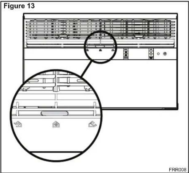
text_image
Figure 13 FRR008Installation Instructions READ THIS FIRST! Electrical Requirements

WARNING
Electrical Shock Hazard
Make sure your electrical receptacle has the same configuration as your air conditioner's plug. If different, consult a Licensed Electrician.
Do not use plug adapters. Do not use an extension cord. Do not remove ground prong.
Always plug into a grounded 3 prong oulet. Failure to follow these instructions can result in death, fire, or electrical shock.
IMPORTANT: Before you begin the actual installation of your air conditioner, check local electrical codes and the information below. Your air conditioner must be connected to a power source with the same alternating current (A.C.) voltage and amperage as marked on the name plate located on the chassis. Only A.C. can be used. Direct Current (D.C.) cannot be used.
CIRCUIT PROTECTION – Use on single outlet circuit only. An overloaded circuit will invariably cause malfunction or failure of an air conditioner, therefore, it is necessary that the electrical protection is adequate. Due to momentary high current demand when the air conditioner starts, use a "TIME DELAY" fuse or a HACR type circuit breaker. Consult your dealer or power company if in doubt.
Refer to the electrical name plate located on the air conditioner chassis (See page 2) to determine the correct fuse or circuit breaker amperage for your model (See Table 1 on Page 6 for electrical receptacle types).
The power cord has a plug with a grounding prong and a matching receptacle is required.
The following instructions are for standard chassis model groups distinguished by the first two letters of the model designations and cabinet sizes listed in Table 3.
| Table 3 | |
| MODEL DESIGNATION C | ABINET SIZE (H x W x D) |
| SMALL CHASSIS - SS, ES, YS | 15^1/5/_16" × 25^1/5/_16" × 29" (405 mm x 660 mm x 737 mm) |
| MEDIUM CHASSIS - SM, EM, YM | 17^1/5/_16" × 25^1/5/_16" × 29" (455 mm x 660 mm x 737 mm) |
| LARGE CHASSIS - SL, EL, YL | 20^3/16" × 28" × 35^1/2" (513 mm x 711 mm x 851 mm) |
WARNING

MOVING PARTS HAZARDS
* Do not operate unit out of sleeve or with front grille removed.
* Do not place hands in blower or fan blade areas.
Failure to do so can result in serious injury.

CAUTION
Excessive Weight Hazard Use two or more people when installing your air conditioner.
Failure to do so can result in back or other injury.
Recommended Tools
- Power Drill
- 5/32" Drill Bit
- Gloves
- Carpenters Level
- 5/16" Wrench
- 1/4" Wrench
-
2 Phillips Screw Driver
- Putty Knife or (wood stir stick)
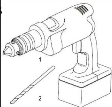
natural_image
Line drawing of a handheld electric drill with two labeled parts (1 and 2), no text or symbols present.
natural_image
Technical line drawing of a rectangular electronic component with four internal slots and a labeled section (no text or symbols)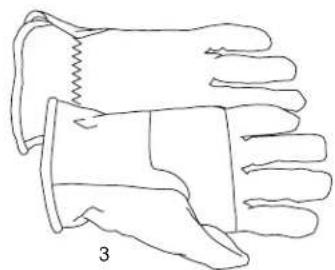
natural_image
Line drawing of a pair of gloves with one partially covered and the other partially covered, labeled '3' (no text or symbols on the gloves themselves)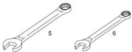
natural_image
Two wrench illustrations labeled 5 and 6, showing different end caps (no text or symbols beyond labels)
natural_image
Two types of screwdrivers shown in line drawings: one with a pointed tip and the other with a flat blade (no text or symbols)ITEMS NOT TO SCALE
INSTALLATION HARDWARE AND ACCESSORY DETAIL
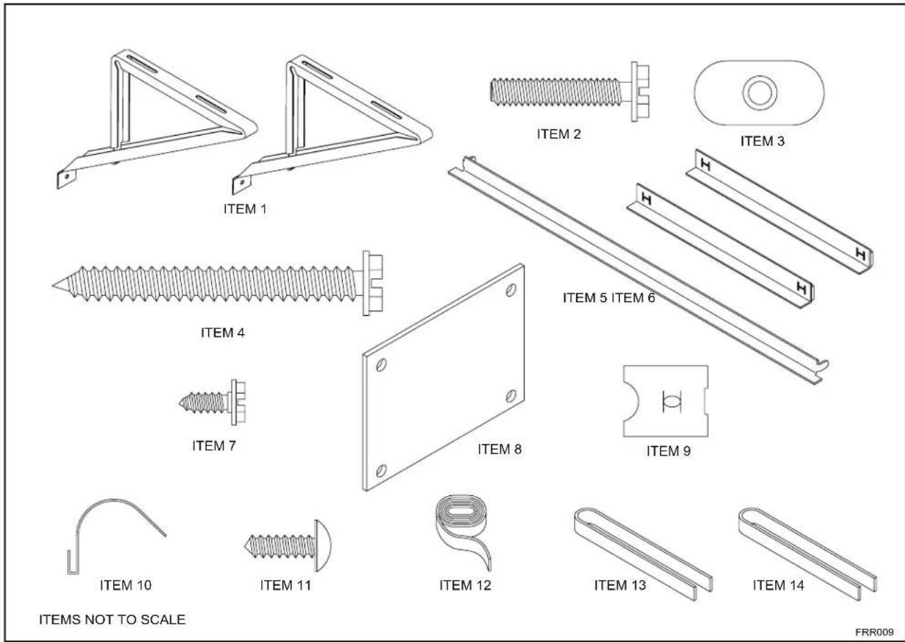
text_image
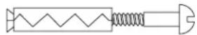
ITEM 1 ITEM 2 ITEM 3 ITEM 4 ITEM 5 ITEM 6 ITEM 7 ITEM 8 ITEM 9 ITEM 10 ITEM 11 ITEM 12 ITEM 13 ITEM 14 ITEMS NOT TO SCALE FRR009Window Mount Installation Hardware
| ITEMNO | DESCRIPTION QTY. | |
| WINGBOARD MOUNTING PARTS8 WINGBOARD (MASONITE) 19 "J" TYPE SPEED NUT 410 WINGBOARD CLIP (SPRING STEEL) 411 SCREW, #8 x 12 " PHILLIPS TRUSS HD. 4 | ||
| WINDOW SEALING12 SEALING GASKET (VINYL) 113 WINDOW SEAL GASKET (DARK FOAM) 114 CHASSIS SEAL GASKET (LIGHT FOAM) | ||
| SHELL MOUNTING PARTS1 SUPPORT BRACKET 22 SCREW, 10-24 x 1" HEX HEAD 43 10-24 FLAT WELD NUT 44 SCREW, SHEET METAL #12 x 2" 7 | ||
| WINGBOARD ANGLE MOUNTING5 WINGBOARD ANGLE, TOP 16 WINGBOARD ANGLE, SIDE 27 SCREW, SHEET METAL #8 x 38 " 2 | ||
Thru-the-wall Installation Hardware
| ITEMNO | DESCRIPTION | QTY. |
| MOUNTING PARTS | ||
| 4 | SCREW, SHEET METAL #12A x 2" | 7 |
| 14 | CHASSIS SEAL GASKET (LIGHT FOAM) | 1 |
NOTE: Kühl + models do not come with window mounting components. When mounting a cooling and heating model a window installation kit must be purchased separately.
KWIKS – For all ES and YS models.
KWIKM – For all EM and YM models.
KWIKL – For all EL and YL models.
Standard Window Installation
NOTE: Hardware and accessories used during installation are shown on page 18. Each part will be referred as Item No.
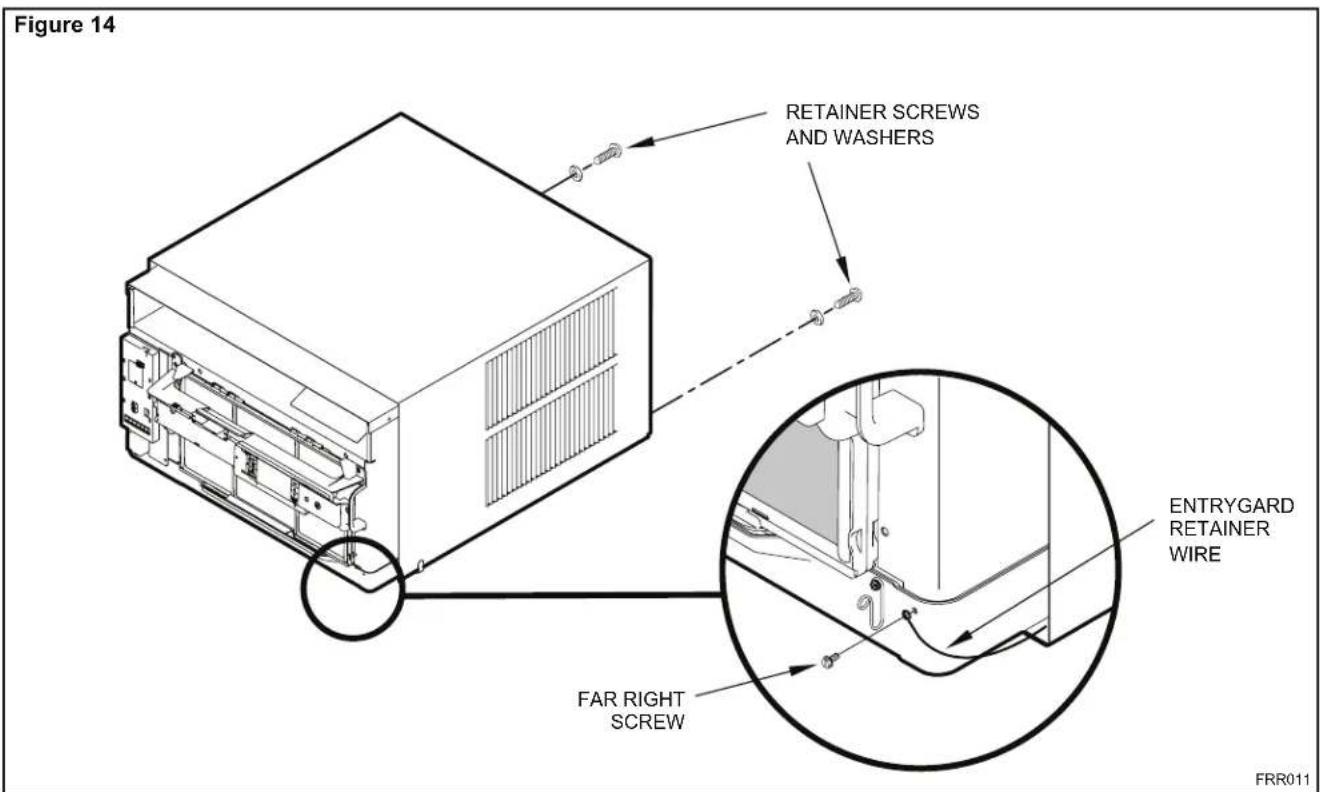
STEP 1. Remove the chassis Entrygard retainer by removing the far right screw (See Figure 14), save this screw to reattach the chassis retainer after installation (Step 12). Also, remove and discard the two retainer screws and washers located at the rear of the unit (See Figure 14).
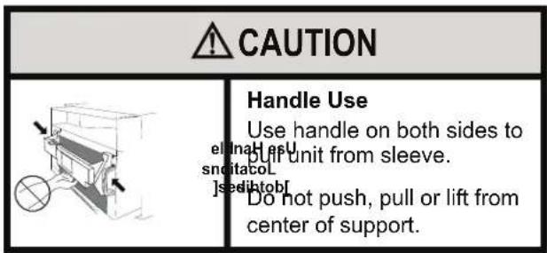
text_image
CAUTION Handle Use Use handle on both sides to pull unit from sleeve. snditacol Jsedihtobf Do not push, pull or lift from center of support.STEP 2. Hold the cabinet stationary, then use the hand grips on both ends of the control unit support bracket to pull the chassis out of the cabinet (See Figure 15).
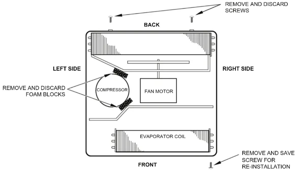
STEP 3. Remove the large white foam blocks used to restrain the compressor during shipment (See Figure 16). Inspect base pan for dislodged white foam blocks and remove. Do not remove any other foam parts.
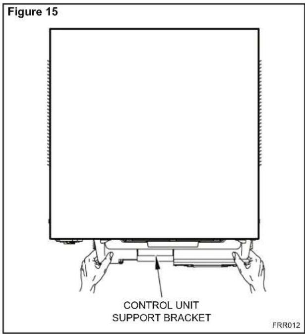
text_image
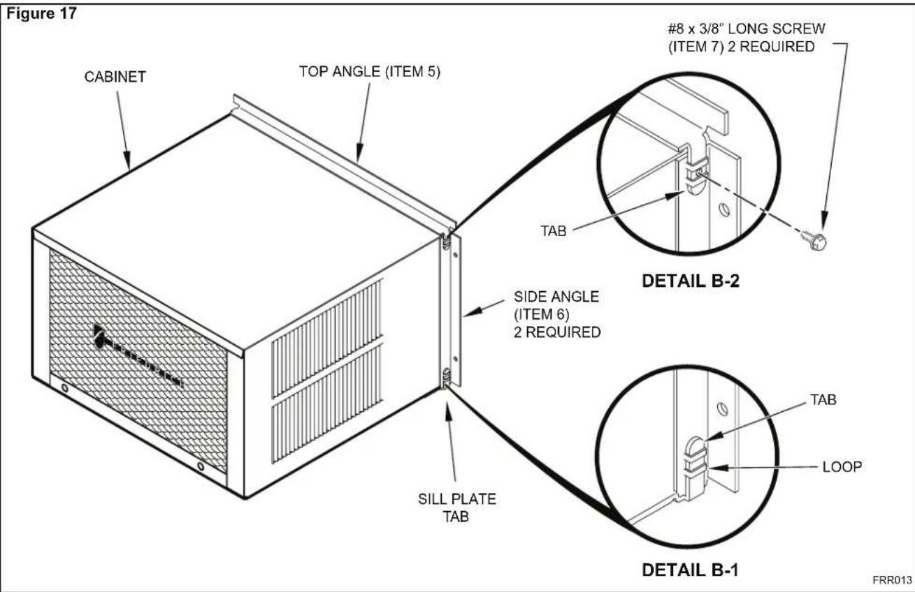
Figure 15 CONTROL UNIT SUPPORT BRACKET FRR012STEP 4. Anchor the side angles (Item 6) by engaging the tabs of the lower sill plate (See Figure 17, Detail B-2) with the loops of the side angle. Engage the tabs of the top angle (Item 5) with the top loops of the side angle (See Figure 17, Detail B-1). Install two (2) screws (Item 7) to secure the top angle tabs and the side angle to the cabinet (See Figure 17, Detail B-1).
text_image
Figure 14 RETAINER SCREWS AND WASHERS ENTRYGARD RETAINER WIRE FAR RIGHT SCREW FRR011CAUTION
Remove Shipping Blocks
Prior to operating the unit remove the foam shipping blocks.
Failure to do so may result in damage to the unit which is not covered by the manufacturer's warranty!
STEP 5. Check the window sill and frame to be sure they are in good condition and firmly anchored to the wall. Repair if necessary.
STEP 6. CABINET MOUNTING – Raise the lower window 1/4" more than the height of the cabinet. Carefully slide the cabinet through the opening until the lower sill plate channel rests behind the window sill and the top angle rests against the window (See Figure 18). Center the cabinet within the opening. Drill three (3) 5/32" diameter pilot holes into window sill using the holes in the cabinet sill plate as a guide. Install three (3) #12 x 2" long screws (Item 4) (See Figure 18).
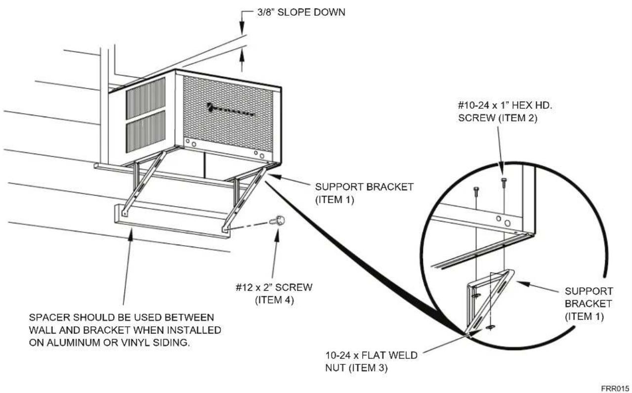
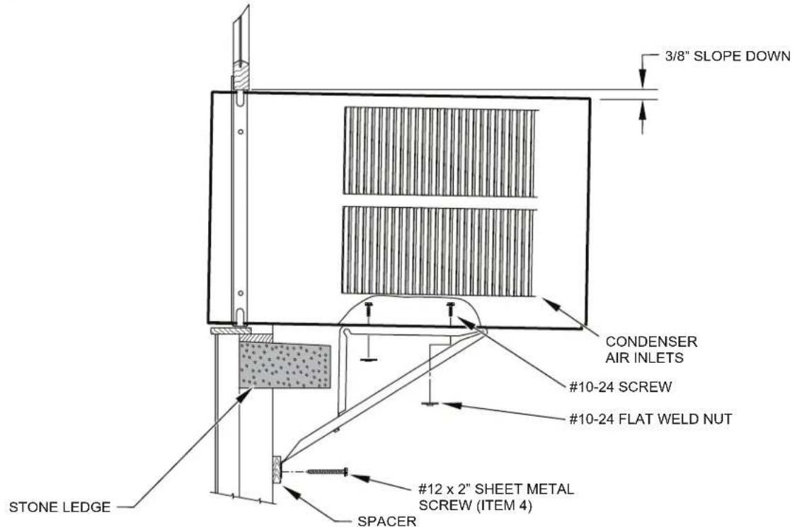
STEP 7. OUTSIDE SUPPORT MOUNTING – Refer to Figures 19 and 20. Assemble the support brackets (Item 1) to the bottom of the cabinet with four (4) 10-24 1" long screws (Item 2) and four 10-24 flat nuts (Item 3). Adjust the support brackets, using a combination of the elongated holes of the bracket and different hole locations in the cabinet, to bring the bottom support bracket pads in contact with the wall. A 1" x 4" or 2" x 4" SPACER SHOULD BE USED BETWEEN THE WALL AND SUPPORT THE BRACKETS WHEN INSTALLED ON ALUMINUM OR VINYL SIDING. Drill 5/32" diameter pilot holes and secure the brackets to the wall with two (2) 12A x 2" long screws (Item 4).
NOTE: DO NOT LEVEL the cabinet from front to back. Make sure there is approximately 3/8" to 1/2" slope (1/8 to 1/4 bubble on level) toward the outside of the house.
Adjust the support brackets to provide an inside-to-outside slope for excess condensation drainage (Refer to Standard Window Installation, Figures 19 through 23). Tighten all screws.
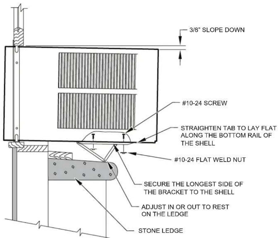
Alternate support method A: If you have a wide window sill which prevents you from mounting the brackets as shown in Figure 22, try the following: Using the elongated holes and different hole locations in the cabinet, set the placement of the bracket to support the unit's weight (Figure 22). Tighten all screws.
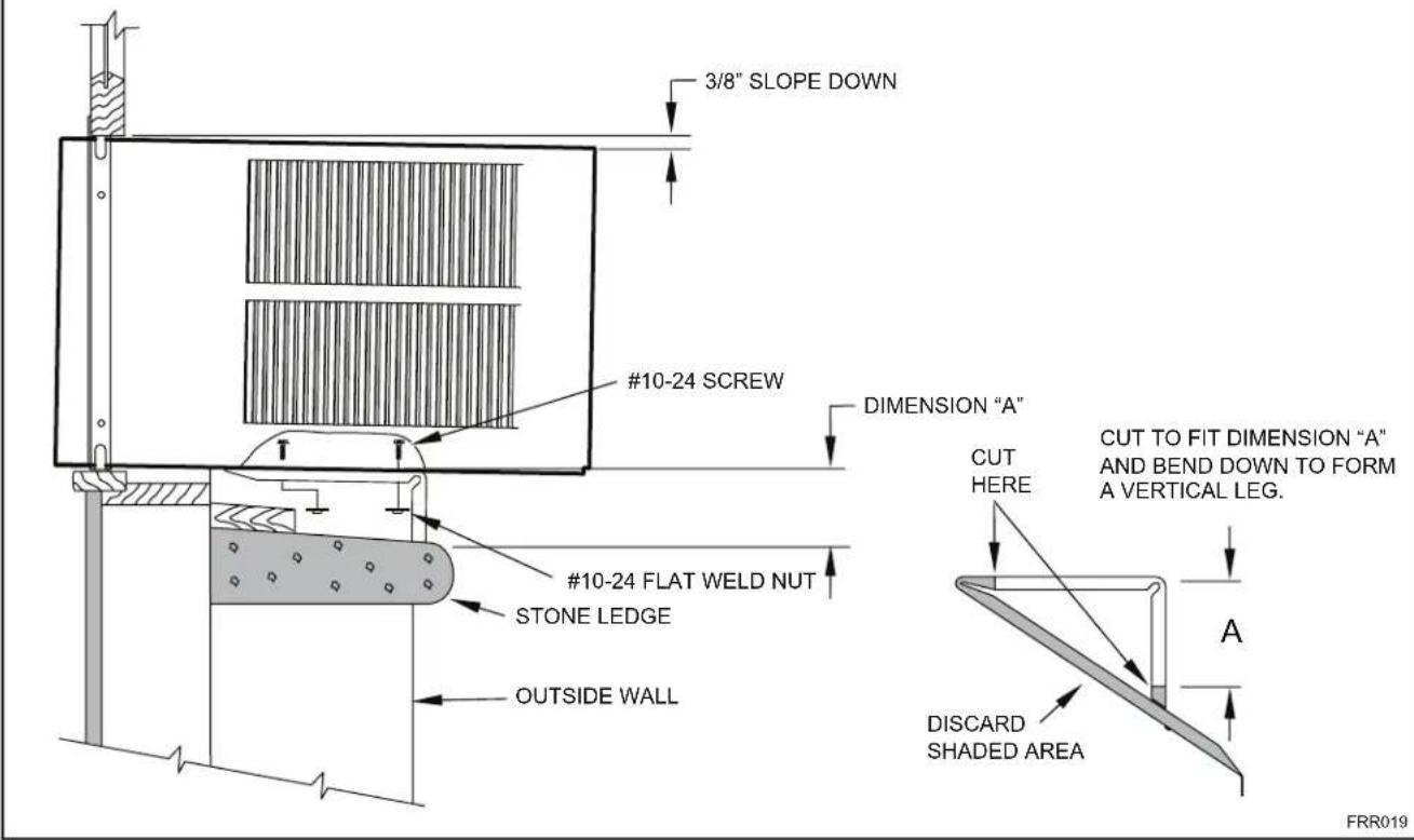
Alternate support method B: If the window ledge gap is narrow, try the following. Bend the bracket end tab flat. Cut the bracket in two (2) places as shown in Figure 23. Bend the short piece so it will be vertical when installed. Adjust the placement as required. Tighten all screws.
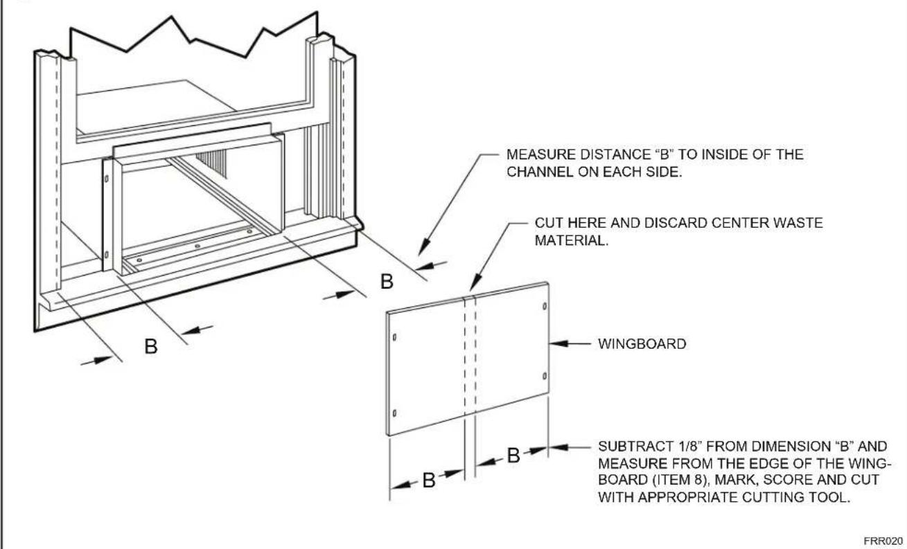
STEP 8. Measure and cut the wingboard panels (fit with about 1/8" clearance) from the supplied Masonite (Item 8) to fit the space between the window side channels and cabinet. (Figure 24). Make sure you include the depth of the window channel.
NOTICE

For YOUR security and safety, YOU must provide a means of preventing the upper part of the window from opening.
STEP 9. To assemble the wingboard panels, push on the "J" type speed nuts (Item 9) and spring steel clips (Item 10) (See Figures 25) on page 26. Secure each panel with two (2) screws (Item 11).
Figure 16
TOP VIEW OF UNIT
text_image
REMOVE AND DISCARD SCREWS BACK LEFT SIDE COMPRESSOR FAN MOTOR RIGHT SIDE EVAPORATOR COIL FRONT REMOVE AND SAVES SCREW FOR RE-INSTALLATIONFRR045
text_image
Figure 17 CABINET TOP ANGLE (ITEM 5) #8 x 3/8" LONG SCREW (ITEM 7) 2 REQUIRED TAB DETAIL B-2 SIDE ANGLE (ITEM 6) 2 REQUIRED SILL PLATE TAB DETAIL B-1 TAB LOOP FRR013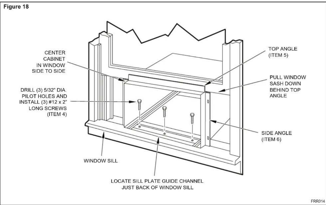
text_image
Figure 18 CENTER CABINET IN WINDOW SIDE TO SIDE DRILL (3) 5/32" DIA. PILOT HOLES AND INSTALL (3) #12 x 2" LONG SCREWS (ITEM 4) TOP ANGLE (ITEM 5) PULL WINDOW SASH DOWN BEHIND TOP ANGLE SIDE ANGLE (ITEM 6) WINDOW SILL LOCATE SILL PLATE GUIDE CHANNEL JUST BACK OF WINDOW SILL FRR014Figure 19
text_image
3/8" SLOPE DOWN #12 x 2" SCREW (ITEM 4) SPACER SHOULD BE USED BETWEEN WALL AND BRACKET WHEN INSTALLED ON ALUMINUM OR VINYL SIDING. SUPPORT BRACKET (ITEM 1) #10-24 x 1" HEX HD. SCREW (ITEM 2) 10-24 x FLAT WELD NUT (ITEM 3) SUPPORT BRACKET (ITEM 1) FRR015Figure 20
text_image
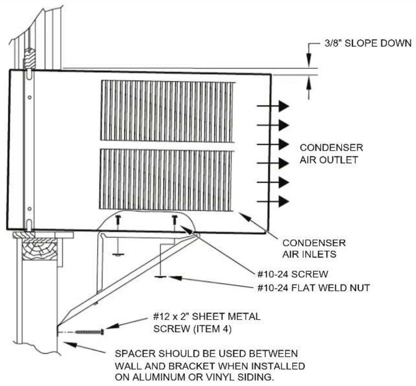
3/8" SLOPE DOWN CONDENSER AIR OUTLET CONDENSER AIR INLETS #10-24 SCREW #10-24 FLAT WELD NUT #12 x 2" SHEET METAL SCREW (ITEM 4) SPACER SHOULD BE USED BETWEEN WALL AND BRACKET WHEN INSTALLED ON ALUMINUM OR VINYL SIDING.FRR016
Figure 21
text_image
3/8" SLOPE DOWN CONDENSER AIR INLETS #10-24 SCREW #10-24 FLAT WELD NUT #12 x 2" SHEET METAL SCREW (ITEM 4) SPACER STONE LEDGEFRR017
Figure 22
text_image
3/8" SLOPE DOWN #10-24 SCREW STRAIGHTEN TAB TO LAY FLAT ALONG THE BOTTOM RAIL OF THE SHELL #10-24 FLAT WELD NUT SECURE THE LONGEST SIDE OF THE BRACKET TO THE SHELL ADJUST IN OR OUT TO REST ON THE LEDGE STONE LEDGEFRR018
Figure 23
text_image
3/8" SLOPE DOWN #10-24 SCREW DIMENSION "A" #10-24 FLAT WELD NUT STONE LEDGE OUTSIDE WALL CUT HERE CUT TO FIT DIMENSION "A" AND BEND DOWN TO FORM A VERTICAL LEG. DISCARD SHADED AREA FRR019Figure 24
text_image
MEASURE DISTANCE "B" TO INSIDE OF THE CHANNEL ON EACH SIDE. CUT HERE AND DISCARD CENTER WASTE MATERIAL. WINGBOARD SUBTRACT 1/8" FROM DIMENSION "B" AND MEASURE FROM THE EDGE OF THE WING-BOARD (ITEM 8), MARK, SCORE AND CUT WITH APPROPRIATE CUTTING TOOL. FRR020STEP 10. INSTALL THE WINDOW SEALING GASKETS – Measure and cut the vinyl window seal gasket (grey color, Item 12) to fit the width of the window, and install as shown in Figure 29. Pull the window sash down behind the gasket. Measure and cut the dark foam window seal gasket (Item 13) and install it between the upper glass panel and the top part of the lower window sash (Figure 29).
CAUTION

Excessive Weight Hazard
Use two or more people when installing your air conditioner.
Failure to do so can result in back or other injury.
CAUTION

Cut/Sever
Although great care has been taken to minimize sharp edges in the construction of your unit, use gloves or other hand protection when handling unit
Failure to do so can result in minor to moderate personal injury.
STEP 11. Carefully team lift the chassis and set it into the cabinet. Slide the chassis stopping approximately 3" from full insertion. Insert the chassis seal gasket (Item 14) one inch deep between the chassis and the cabinet (See Figure 29) as shown on page 28. A paint stir stick or ruler might be helpful here. Begin inserting the gasket at either bottom corner and go up the side, across the top, and down the opposite side. Then push the chassis all the way into the cabinet.
NOTE: If the chassis seal gasket is not installed or installed improperly, the operation of the unit will be negatively affected. Operational noise and outside noise will also be amplified.
STEP 12. Reattach the entry guard chassis entry guard retainer wire with the same screw retained in Step 1 (See Figure 14).
Figure 25
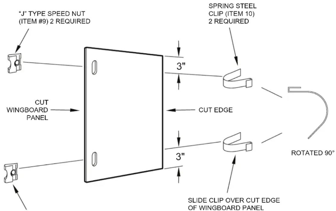
text_image
"J" TYPE SPEED NUT (ITEM #9) 2 REQUIRED SPRING STEEL CLIP (ITEM 10) 2 REQUIRED 3" CUT WINGBOARD PANEL 3" CUT EDGE 3" SLIDE CLIP OVER CUT EDGE OF WINGBOARD PANEL ROTATED 90°CENTER THE HOLE IN THE SPEED NUT OVER THE SLOT IN THE WINGBOARD PANEL
FRR021
text_image
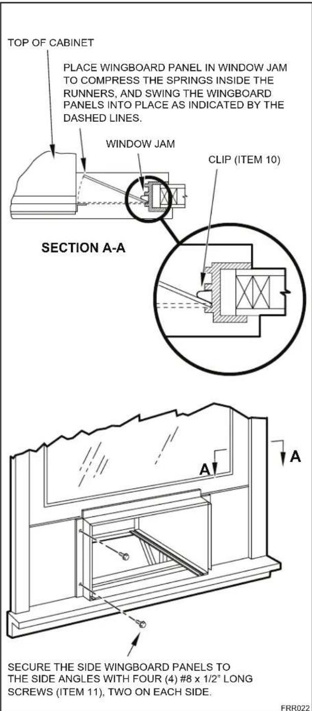
TOP OF CABINET PLACE WINGBOARD PANEL IN WINDOW JAM TO COMPRESS THE SPRINGS INSIDE THE RUNNERS, AND SWING THE WINGBOARD PANELS INTO PLACE AS INDICATED BY THE DASHED LINES. WINDOW JAM CLIP (ITEM 10) SECTION A-A A A SECURE THE SIDE WINGBOARD PANELS TO THE SIDE ANGLES WITH FOUR (4) #8 x 1/2" LONG SCREWS (ITEM 11), TWO ON EACH SIDE. FRR022Figure 27 Figure 26
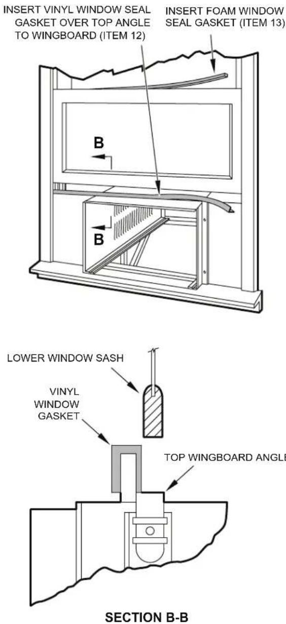
text_image
INSERT VINYL WINDOW SEAL GASKET OVER TOP ANGLE TO WINGBOARD (ITEM 12) INSERT FOAM WINDOW SEAL GASKET (ITEM 13) LOWER WINDOW SASH VINYL WINDOW GASKET TOP WINGBOARD ANGLE SECTION B-BOPTIONAL: The factory assembles the supply cord so that it exits the left side of the unit at the bottom. At the consumer's discretion,
To do this, route the supply cord to the right side. Pull the supply cord taunt through the loops (Refer to Cord Routing Change, Figure 30) and route the cord down.
STEP 13. To attach and prevent damage to the front grille align the cord notch over the cord and center the fresh air lever, then align and tighten the four (4) captive screws as indicated by the arrows in Figure 28. Before closing the front panel, be sure the filter is in place. Make sure curtains do not block the side air intakes.
STEP 14. Refer to the Control Panel Operation section for instructions.
STEP 15. You are now ready to control the comfort level of the room.
Use Tool Provided
.tinu eht foRdeasingisethedipcofidedutopelraRadnothelpoerative front to the chassis.
Figure 28
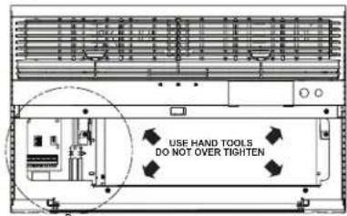
text_image
USE HAND TOOLS DO NOT OVER TIGHTENLOCATION OF GRILLE REMOVAL TOOL
text_image
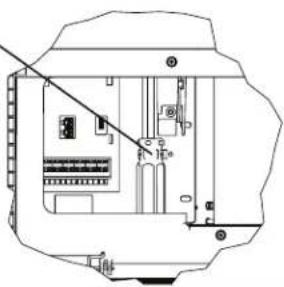
Technical diagram of an electrical enclosure with labeled components and wiring connectionsFRR053
Figure 29
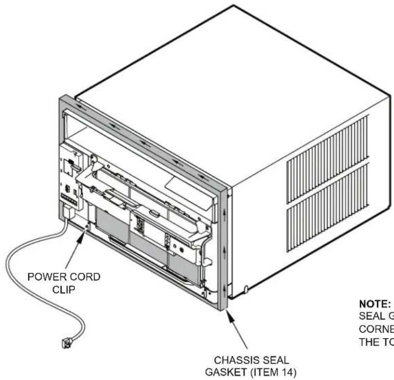
text_image
POWER CORD CLIP CHASSIS SEAL GASKET (ITEM 14) NOTE: SEAL G CORNE THE TONOTE: WHEN INSTALLING THE CHASSIS SEAL GASKET; BEGIN AT EITHER BOTTOM CORNER AND GO UP THE SIDE & ACROSS THE TOP & DOWN THE OPPOSITE SIDE.
FRR024
THIS PAGE INTENTIONALLY LEFT BLANK
Cord Routing Change
Unplug unit.
WARNING

Electrical Shock Hazard
Make sure your electrical receptacle has the same configuration as your air conditioner's plug. If different, consult a Licensed Electrician.
Do not use plug adapters.
Do not use an extension cord.
Do not remove ground prong.
Always plug into a grounded 3 prong outlet. Failure to follow these instructions can result in death, fire, or electrical shock.
For convenience and optimum appearance the direction that the power cord exits the unit may be changed from left to right by following the procedure below. Select the exit location on the left or right based on proximity to the power outlet.
Figure 30
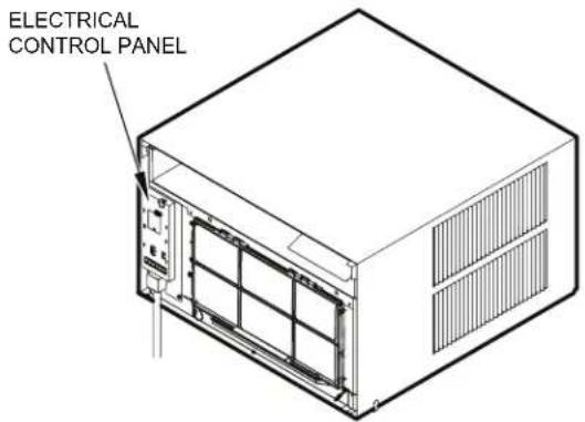
text_image
ELECTRICAL CONTROL PANELNOTE:
DECORATIVE FRONT REMOVED USE TOOL PROVIDED.
(SEE FIGURE 28 FOR LOCATION OF TOOL).
FRR054
Remove 3 screws as shown from the electrical control panel. Save to reinstall later.
Figure 31
ELECTRICAL CONTROL PANEL SCREWS (3)
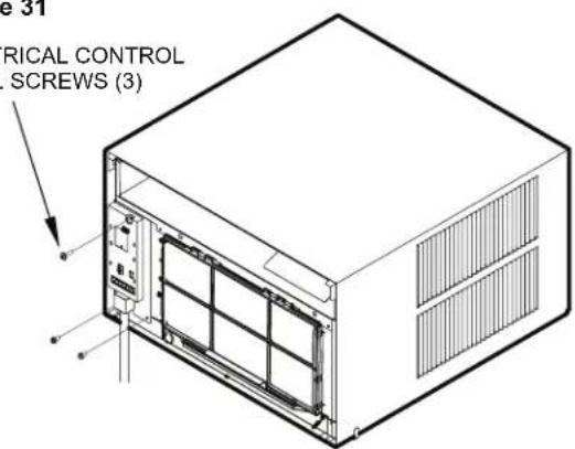
text_image
e 31 RICAL CONTROL SCREWS (3)FRR055
STEP 16. Carefully pull out electrical control panel 1", but not all the way.
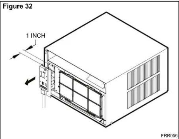
text_image
Figure 32 1 INCH FRR056STEP 17. Pull electrical cord strain relief downward until free and rotate 90 degrees to the right.
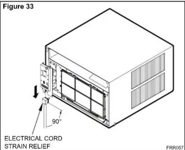
text_image
Figure 33 ELECTRICAL CORD STRAIN RELIEF 90° FRR057STEP 18. Push electrical cord strain relief back upward into the electrical control panel.
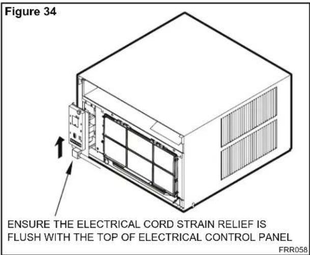
text_image
Figure 34 ENSURE THE ELECTRICAL CORD STRAIN RELIEF IS FLUSH WITH THE TOP OF ELECTRICAL CONTROL PANEL FRR058STEP 19. Carefully push electrical control panel back into chassis.
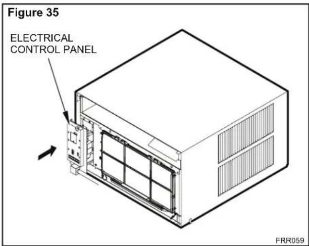
text_image
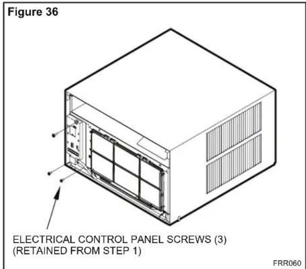
Figure 35 ELECTRICAL CONTROL PANEL FRR059STEP 20. Reinstall the 3 screws removed earlier to secure electrical control panel.
text_image
Figure 36 ELECTRICAL CONTROL PANEL SCREWS (3) (RETAINED FROM STEP 1) FRR060STEP 21. If running power cord to the right of the unit install the cord into the cord retainer clips along the bottom front of the unit.
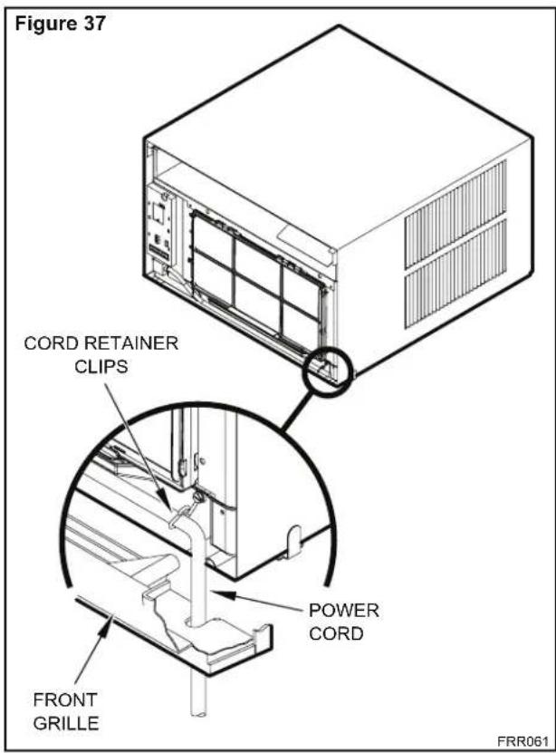
text_image
Figure 37 CORD RETAINER CLIPS POWER CORD FRONT GRILLE FRR061Through-the-Wall Installation
The following instructions apply to wood, masonry, brick, concrete or cinder block wall construction.
STEP 1. Follow steps 1, 2, 3, and 4 of the "STANDARD WINDOW INSTALLATION" instructions beginning on page 20.
STEP 2. CABINET PREPARATION – Remove the sill plate from the cabinet by removing two (4) nuts and screws (Figure 38). Note that the chassis retainer is secured by a right side nut and screw (Detail A, Figure 38). Bend the tabs of the sill plate down into its channel at both ends of the plate or cut them off (Detail B, Figure 38) Rotate the sill plate 180° (end-to-end, Detail B, Figure 38) and reinstall. Reverse the orientation of the nuts and screws, so that the head of the screws are on the underside of cabinet facing up and the nuts are on top (Detail C, Figure 38). Ensure that the chassis retainer is reinstalled as shown in the detail.
NOTICE
The outside cabinet condenser air intake louvers MUST NOT BE BLOCKED by extra thick walls.
STEP 3. WALL PREPARATION – The maximum wall thickness permissible without special construction is determined by the model size to be installed. Observe the maximum wall thickness shown in Figure 39. Walls exceeding the maximum thickness shown in the chart, should be altered as shown in Figure 39.
STEP 4. CHECKING WIRING AND PLUMBING – Check for wiring and plumbing inside and outside of the wall to be sure none will be damaged when the cabinet framework is being constructed.
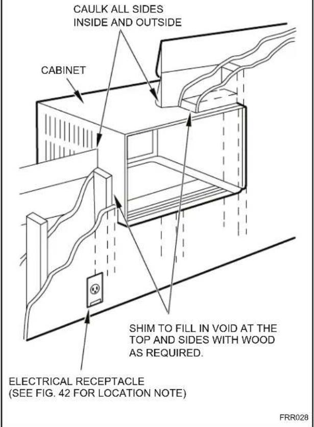
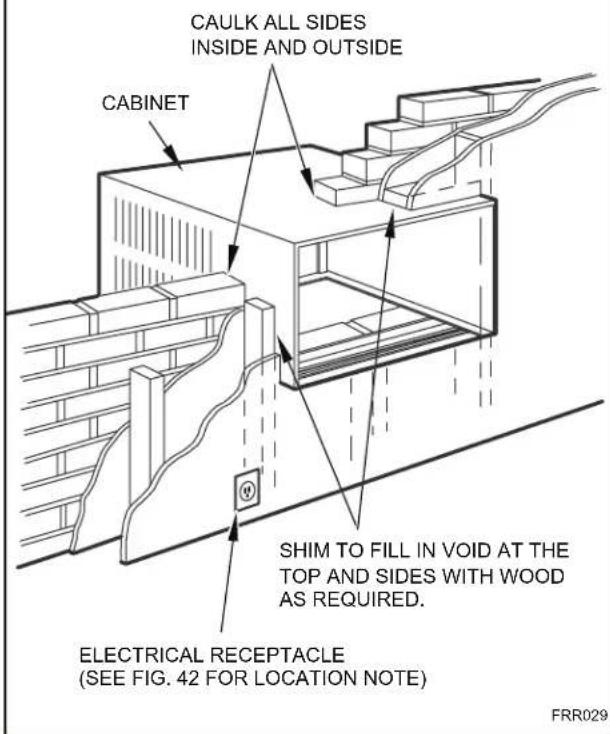
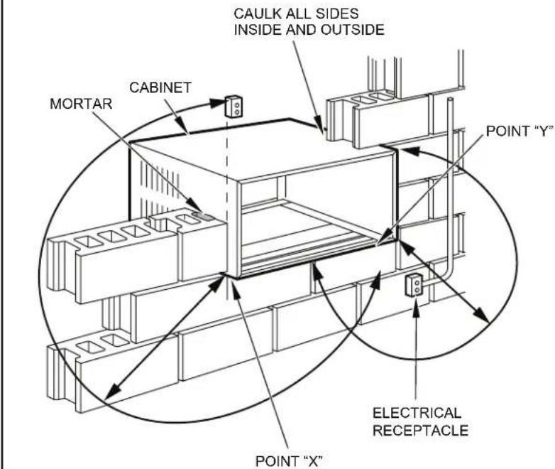
STEP 5. OPENING CONSTRUCTION – Depending upon size of unit to be installed, lay out the hole dimensions per Table 4. Cut and frame-in the opening to finished dimensions. If the wall construction is typical frame or 2" x 4" studding with brick or stone veneers, locate the opening next to one of the studs. For masonry, concrete or cinder block walls, locate opening for your convenience (See Figures 40, 41, and 42).
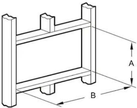
natural_image
Technical line drawing of a structural frame with labeled dimensions A and B (no text or symbols beyond labels)| Table 4 | |||
| FINISHED DIMENSION | SMALL CHASSIS | MEDIUM CHASSIS | LARGE CHASSIS |
| A 16 | ^3/_16 " 18 | ^3/_16 " 20 | ^3/_8 " |
| B 26 | ^3/_16 " 26 | ^3/_16 " 28 | ^1/_4 " |
| Note: These dimensions are for finished opening size. | |||
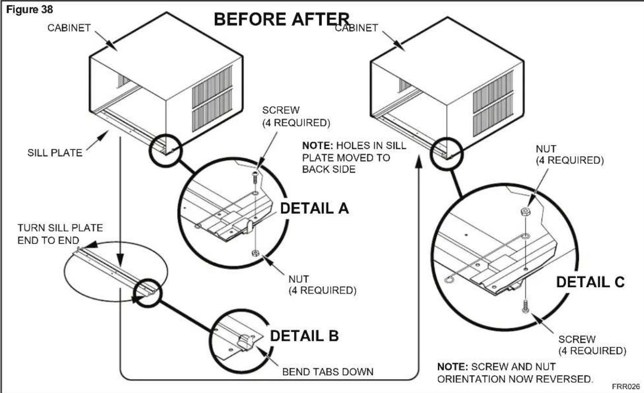
flowchart
graph TD
    A["SILL PLATE"] --> B["CABINET"]
    B --> C["BEFORE AFTER"]
    C --> D["NOTE: Holes in SILL PLATE MOVED TO BACK SIDE"]
    D --> E["Screw (4 REQUIRED)"]
    E --> F["DETAIL A"]
    F --> G["NUT (4 REQUIRED)"]
    G --> H["DETAIL B"]
    H --> I["BEND TABS DOWN"]
    I --> J["NOTE: SCREW AND NUT ORIENTATION NOW REVERSED."]
    J --> K["DETAIL C"]
    K --> L["NUT (4 REQUIRED)"]
    L --> M["DETAIL A"]
Figure 39
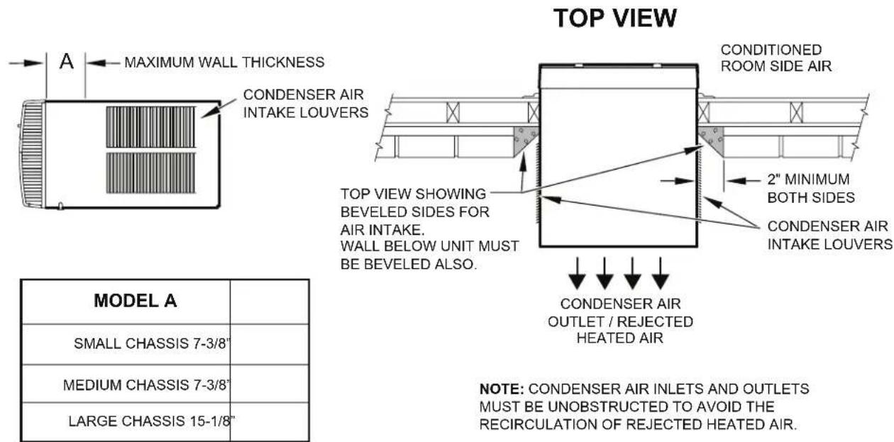
text_image
TOP VIEW A MAXIMUM WALL THICKNESS CONDENSER AIR INTAKE LOUVERS CONDITIONED ROOM SIDE AIR 2" MINIMUM BOTH SIDES CONDENSER AIR INTAKE LOUVERS TOP VIEW SHOWING BEVELED SIDES FOR AIR INTAKE. WALL BELOW UNIT MUST BE VELED ALSO. CONDENSER AIR OUTLET / REJECTED HEATED AIR MODEL A SMALL CHASSIS 7-3/8" MEDIUM CHASSIS 7-3/8" LARGE CHASSIS 15-1/8" NOTE: CONDENSER AIR INLETS AND OUTLETS MUST BE UNOBSTRUCTED TO AVOID THE RECIRCULATION OF REJECTED HEATED AIR.FRR027
Figure 40
text_image
CAULK ALL SIDES INSIDE AND OUTSIDE CABINET SHIM TO FILL IN VOID AT THE TOP AND SIDES WITH WOOD AS REQUIRED. ELECTRICAL RECEPTACLE (SEE FIG. 42 FOR LOCATION NOTE) FRR028Figure 41
text_image
CAULK ALL SIDES INSIDE AND OUTSIDE CABINET SHIM TO FILL IN VOID AT THE TOP AND SIDES WITH WOOD AS REQUIRED. ELECTRICAL RECEPTACLE (SEE FIG. 42 FOR LOCATION NOTE) FRR029Figure 42
text_image
CAULK ALL SIDES INSIDE AND OUTSIDE MORTAR CABINET POINT "Y" ELECTRICAL RECEPTACLE POINT "X"| From Point "X" Small/Medium Large | |
| 115V 69" N/A | |
| 230V 45" 45" | |
| From Point "Y" Small/Medium Large | |
| 115V 45" N/A | |
| 230V 21" 20" | |
FRR030
STEP 6. Slide the cabinet into the hole far enough to allow the guide-channel of the sill plate to contact the inside wall surface (Figure 20).
STEP 7. Drill three (3) 5/32" diameter pilot holes (use the sill-plate holes as a guide) into the frame and install three (3) #12 x 2" long screws (Item 4) (Figure 20).
NOTE: Alternate fasteners are required when securing the sill plate or support brackets to material other than wood (cinder block, brick, masonry or concrete). These items can be purchased at your local hardware store.
EXPANSION ANCHOR BOLT
MOLLY OR TOGGLE BOLT
NOTE: DO NOT LEVEL the cabinet from front to back. Make sure there is approximately 3/8" to 1/2" slope (1/8 to 1/4 bubble on the level) toward the outside of the house.
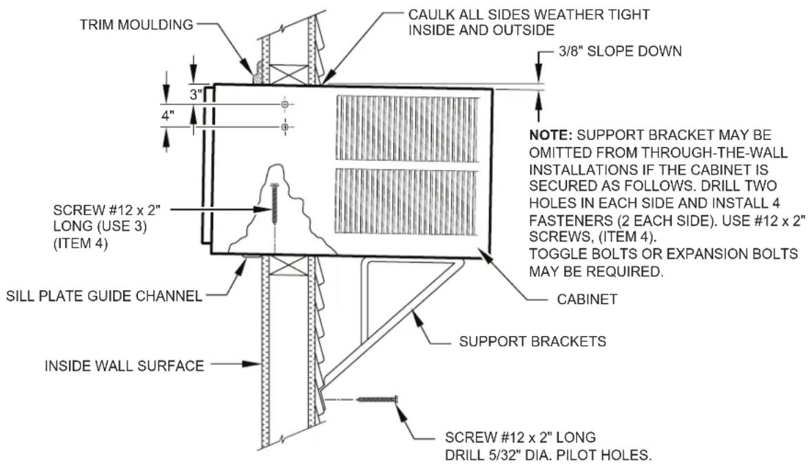
STEP 8. Drill two (2) 5/32" diameter pilot holes in each cabinet side at the locations shown (Figure 20) and install four (4) #12 x 2" screws (Item 4). Provided that Step 5 (hole construction) provides a sturdy mount with solid vertical studs, support brackets may not be required. The installation must support the weight of the unit plus an additional weight of 400 pounds on the rear of the cabinet. If support brackets (Item 1) are available, they can be installed as shown in Figure 20.
STEP 9. Complete the installation by following steps 12 through 15 of "STANDARD WINDOW INSTALLATION" instructions, page 20.
Figure 43
text_image
TRIM MOULDING CAULK ALL SIDES WEATHER TIGHT INSIDE AND OUTSIDE 3/8" SLOPE DOWN 3" 4" NOTE: SUPPORT BRACKET MAY BE OMITTED FROM THROUGH-THE-WALL INSTALLATIONS IF THE CABINET IS SECURED AS FOLLOWS. DRILL TWO Holes IN EACH SIDE AND INSTALL 4 FASTENERS (2 EACH SIDE). USE #12 x 2" SCREWS, (ITEM 4). TOGGLE BOLTS OR EXPANSION BOLTS MAY BE REQUIRED. Screw #12 x 2" LONG (USE 3) (ITEM 4) SILL PLATE GUIDE CHANNEL CABINET SUPPORT BRACKETS INSIDE WALL SURFACE SCREW #12 x 2" LONG DRILL 5/32" DIA. PILOT HOLES.FRR031
Programmable Thermostat
Your unit's digital control features an advanced 7 day programmable thermostat feature that can be used to turn the unit on or off or even change modes and maintain temperatures throughout the day.
Factory settings are shown in addendum 1 (Schedule Table with Energy Saving Values). These values can be changed by following the procedures in the preceding paragraphs. Basic options are: Four (4) day groups.
- Monday through Friday.
- Saturday and Sunday only.
- Monday through Sunday.
- Individual days (Mon thru Sun).
Each of the day groups have four (4) time periods: WAKE (06:00), AWAY (08:00), RETURN (18:00), and NIGHT (22:00).
The start time for each of the time periods can be changed. In addition, each time period can have its own temperature and fan mode.
For example, let's say you are in a cool climate region. You leave for work at 08:00 and return home around 18:30. You can set the temperature lower while you are away from your home. At 18:00, you set the temperature higher for the RETURN period so the room is nice and comfortable when you arrive.
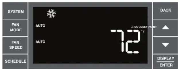
Set Schedule Sequence - 1 Wake Period
text_image
SYSTEM FAN MODE FAN SPEED SCHEDULE AUTO AUTO 7-2 COOLSET POINT °F BACK ▲ ▼ DISPLAY ENTERFRR032
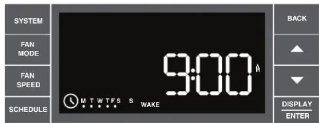
Press and hold 📄 for three (3) seconds to enter the schedule setting mode. If left inactive for five (5) minutes, the unit exits the schedule setting mode and returns to normal display without saving any settings that might have been changed. To exit and save the changes, press and hold 📄 for three (3) seconds. All changed parameters will be saved. The key allows the user to back up through the menus.
text_image
SYSTEM FAN MODE FAN SPEED SCHEDULE 9:00 MTWTFSS WAKE BACK ▲ ▼ DISPLAY ENTERFRR033
When the schedule setting mode is entered, a confirmation sound plays and the schedule icon blinks. The display begins with all weekday (MTWTF) dots lit. Changes made will apply equally to all weekdays.
text_image
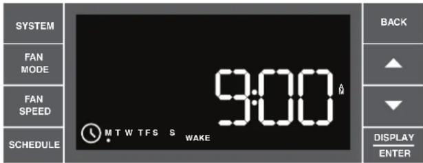
SYSTEM FAN MODE FAN SPEED SCHEDULE 9:00 MTW TFS S WAKE BACK ▲ ▼ DISPLAY ENTERFRR034
The user can select a different day group by pressing . User continues to press system will cycle through all the day groups in the following order: MTWTF SS Mon, Tues, Wed, Thur, , Sat, Sun. Note the last day group is each individual day. In other words, the user can adjust each of the four (4) time period start times per day. This is a real helpful feature if you have an adjustable work shift. Each day group begins showing the start time for the wake time period.
text_image
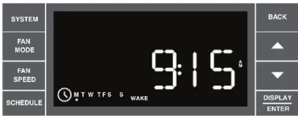
SYSTEM FAN MODE FAN SPEED SCHEDULE 9:15 MTW TFS S WAKE BACK ▲ ▼ DISPLAY ENTERFRR035
To change the time, press ▲ (UP) or ▼ (DOWN) to increment/decrement the time by 15 minute jumps. Once the correct time is set, press ▶ ENTER to advance to the next step.
Set Schedule Sequence - 2 Wake Period
text_image
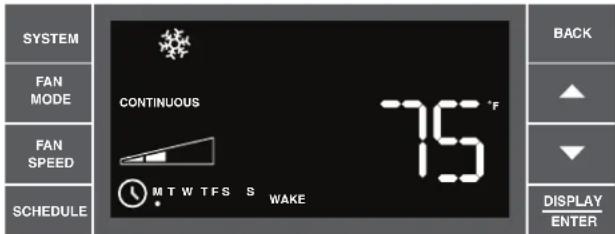
SYSTEM FAN MODE FAN SPEED SCHEDULE CONTINUOUS MTW TFS S WAKE 75 °F BACK ▲ ▼ DISPLAY ENTERFRR036
Now you can adjust the settings for SYSTEM, FAN MODE, FAN SPEED and TEMPERATURE.
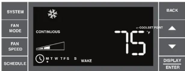
text_image
SYSTEM FAN MODE FAN SPEED SCHEDULE CONTINUOUS MTW TFS S WAKE COOLSET POINT F BACK ▲ ▼ DISPLAY ENTERFRR037
Press SYSTEM FAN MCGE FAN HED UP (DOWN) to adjust the cool setpoint.

text_image
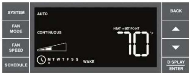
SYSTEM FAN MODE FAN SPEED SCHEDULE AUTO CONTINUOUS HEAT→SET POINT 70 °F MTWTFSS WAKE BACK ▲ ▼ DISPLAY ENTERFRR038
If the system mode is set to AUTO (Heat-Cool Unit only), a 2nd temperature labeled "Heat → Set Point" displays. Use ▲(UP) or ▼(DOWN) arrows to increment/decrement the heat temperature. The other parameters (SYSTEM, FAN SPEED, FAN MODE) cannot be changed on this screen. The temperature range for AUTO mode must remain a minimum of 3 degrees apart at all times. If the high or low temperature is adjusted too close to its counterpart, that temperature not being directly changed will increase/decrease as needed to maintain the 3 degree spread. The user presses DISPLAY ENTER to advance to the next time period.
text_image
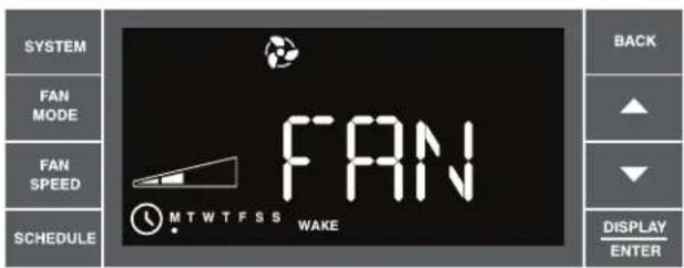
SYSTEM FAN MODE FAN SPEED SCHEDULE FAN MTWTFSS WAKE BACK ▲ ▼ DISPLAY ENTERFRR039
If the user selects FAN-Only mode, the word FAN displays for 2 seconds. In this mode you may adjust the FAN SPEED. The FAN SPEED options are: LOW, MED, HIGH or MAX*. Fan speed depends on your unit's model. The MAX* Setting is available on all SS and SM models.
text_image
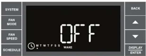
SYSTEM FAN MODE FAN SPEED SCHEDULE OFF MTWTFSS WAKE BACK ▲ ▼ DISPLAY ENTERFRR040
If the user wants the air conditioner to power down for a period of time, pressing system a fifth time will set the unit options to OFF and put the unit into hibernation until the next scheduled period. This feature is available during schedule setup only. In on-the-fly use, the user just presses the power button.
text_image
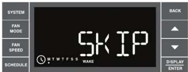
SYSTEM FAN MODE FAN SPEED SCHEDULE SKIP MTWTFSS WAKE BACK ▲ ▼ DISPLAY ENTERFRR041
If the user should decide they don't want to use any or all four time periods for the day, they can set any period to be pressing SYSTEM This will blank out the options and display the word SKIP. This can be undone by pressing SYSTEM again. The digital control defaults to the time period setting immediately prior to the user advancing to SKIP. Press DISPLAY, continue continue on to the next time period. SKIP continues the settings of the previous time period, it will terminate at the start of the next time period where SKIP is not selected.
Set Schedule – Away, Return, Night Periods
text_image
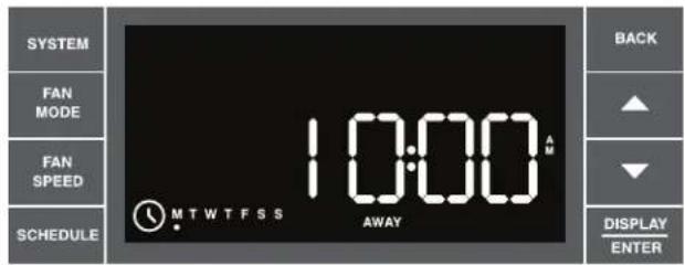
SYSTEM FAN MODE FAN SPEED SCHEDULE 10:00 MTWTFSS AWAY BACK ▲ ▼ DISPLAY ENTERFRR042
Each of the additional periods (Away, Return, Night) are programmed identical to the programming for the Wake period. The appropriate period identifier (Away, Return, Night) displays during each programming sequence.
Once the user has programmed all four (4) time periods, the program goes to the next day or day group by pressing SCHEDULE. For example, if individual days are being programmed, the program will go from Mon to Tues leading the user through 4 periods for Tues until it reaches the end of the week.
NOTE: Day group sequence is as follows: Monday through Friday (weekday), Saturday – Sunday (weekend), Monday through Sunday (7-day), and individual days Mon → Tue → Wed → Thru
Note that by pressing SCHEDULE repeatedly the process follows a continuous loop until the user decides to exit.
When the user has completed setting start times and options (or at any point in the process) they can press 📄 toggle to the next day (or set of days), or they can press and hold 📄 for 3 seconds to save their changes and exit the set schedule mode. Once programmed you can SAVE and EXIT or select another day group by pressing SCHEDULE.
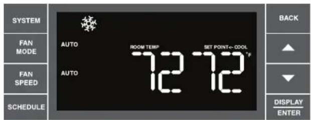
text_image
SYSTEM FAN MODE FAN SPEED SCHEDULE AUTO ROOM TEMPLE 12 12 SET POINT=COOL °F BACK ▲ ▼ DISPLAY ENTERSchedule Mode Completed.
FRR043
Final Inspection & Start-up Checklist
- Inspect and ensure that all components and accessories have been installed properly and that they have not been damaged during the installation progress.
◆ Check the condensate water drain(s) to ensure that they are adequate for the removal of condensate water, and that they meet the approval of the end user.
◆ Ensure that all installation instructions concerning clearances around the unit have been adhered to. Check to ensure that the unit air filter, indoor coil, and outdoor coil are free from any obstructions.
◆ Ensure that the circuit breaker(s) or fuse(s) and supply circuit wire size have been sized correctly. If the unit was supplied with a power supply cord, insure that it is stored properly.
◆ Ensure that the entire installation is in compliance with all applicable national and local codes and ordinances having jurisdiction.
◆ Secure components and accessories, such as a decorative front cover.
◆ Start the unit and check for proper operation of all components in each mode of operation.
◆ Instruct the owner or operator of the units operation, and the manufacturer's Routine Maintenance.
NOTE: A log for recording the dates of maintenance and/or service is recommended.
Present the owner or operator of the equipment with the Installation & Operation Manual, all accessory installation instructions, and the name, address and telephone number of the Authorized Friedrich Warranty Service Company in the area for future reference if necessary.
This is a warm weather appliance
Your air conditioner is designed to cool in warm weather when the outside temperature is above 60°F (15.6°C) and below 115°F (46.1°C), so it won't cool a room if it is already cool outside. If you want to cool a room in the spring or fall, select the FAN ONLY mode and set the Fresh Air/Exhaust air control to Fresh Air. This will bring in a supply of cooler outside air.
Condensation is normal
Air conditioners actually pump the heat and humidity from your room to the outside. Humidity becomes water, and your air conditioner will use most of the water to keep the outside coil cool. If there is excessive humidity, there may be excess water that will drip outside. This is normal operation.
Frosting
This usually occurs because of insufficient airflow across the coils, a dirty filter, cool damp weather, or all of these. Set the SYSTEM mode to FAN ONLY and the frost will disappear. Setting the thermostat a little warmer will probably prevent the frosting from recurring.
Noises
All air conditioners make some noise. Friedrich units are designed to operate as quietly as possible. An air conditioner mounted in a wall is quieter than one mounted in a window. It is important to ensure that the chassis seal gasket (Item 14) is properly installed (refer to installation instructions).
Heat pumps operate differently
If your unit is a "Y", or heat pump model, there are some things that you will want to be aware of. Some functions of a heat pump differ from your unit when it is used for heating:
- It is normal for ice to form on the outdoor coil of the heat pump. Moisture in the outside air, passing over the coil when very cold, will form ice.
- If the outdoor temperature drops below 37^ F ( 3^ C), your heat pump will automatically turn on the electric resistance heat. When the temperature rises to 40^ F ( 4^ C), the compressor will resume the heat pump operation. If your unit is a 115 volt model (YS10), it is designed for use in warmer climates and does not have an electrical heat feature, and will not provide adequate heat below 37^ F ( 2.8^ C).
Control Panel Battery Change Procedure
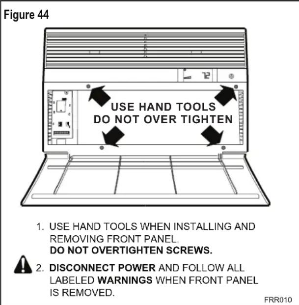
Remove the grille, by loosening four (4) captive screws (See Figure 44). In the upper left corner, remove one (1) screw on the battery retaining door (See Figure 45). Remove and replace the battery (CR2450). Reinstall the battery retaining door. Align the grille guide pins then tighten the four (4) captive screws. Before closing the grille panel door, check the filter. Clean or replace it as necessary.
text_image
Figure 44 USE HAND TOOLS DO NOT OVER TIGHTEN 1. USE HAND TOOLS WHEN INSTALLING AND REMOVING FRONT PANEL. DO NOT OVERTIGHTEN SCREWS. 2. DISCONNECT POWER AND FOLLOW ALL LABELED WARNINGS WHEN FRONT PANEL IS REMOVED. FRR010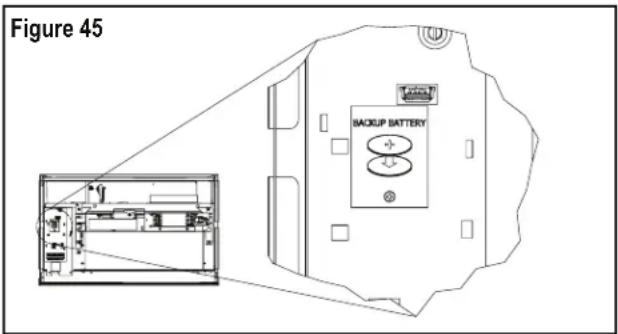
text_image
Figure 45 BACKUP BATTERYRoutine Maintenance
To ensure proper unit operation, the air filters should be cleaned at least monthly, and more frequently if conditions warrant. The unit must be turned off before the filters are cleaned.
| WARNING | |
| Electrical Shock Hazard Make sure your electrical receptacle has the same configuration as your air conditioner's plug. If different, consult a Licensed Electrician. Do not use plug adapters. Do not use an extension cord. Do not remove ground prong. Always plug into a grounded 3 prong oulet. Failure to follow these instructions can result in death, fire, or electrical shock. | |
To Remove, Wash and Replace Filter
Lower front panel (See Figure 2). Use handle on filter to flex filter up and out of retainer. Remove filter from unit (See Figure 3). Clean filter monthly or more frequently if needed. Refer to accessories section for filter options.
Coils & Chassis
NOTE: Do not use a caustic coil cleaning agent on coils or base pan. Use a biodegradable cleaning agent and degreaser. The use of harsh cleaning materials may lead to deterioration of the aluminum fins or the coil end plates.
The indoor coil and outdoor coils and base pan should be inspected periodically (annually or semi-annually) and cleaned of all debris (lint, dirt, leaves, paper, etc.) as necessary. Under extreme conditions, more frequent cleaning may be required. Clean the coils and base pan with a soft brush and compressed air or vacuum. A pressure washer may also be used, however, you must be careful not to bend the aluminum fin pack. Use a sweeping up and down motion in the direction of the vertical aluminum fin pack when pressure cleaning coils.
NOTE: It is extremely important to insure that none of the electrical and/or electronic parts of the unit get wet. Be sure to cover all electrical components to protect them from water or spray.
Decorative Front
Use a damp (not wet) cloth when cleaning the control area to prevent water from entering the unit, and possibly damaging the electronic control.
The decorative front and the cabinet can be cleaned with warm water and a mild liquid detergent. Do NOT use solvents or hydrocarbon based cleaners such as acetone, naphtha, gasoline, benzene, etc.
The indoor coil can be vacuumed with a dusting attachment if it appears to be dirty. DO NOT BEND FINS. The outdoor coil can be gently sprayed with a hose if you can get to it. If not, you might call your dealer for a more thorough cleaning when needed.
The air filter should be inspected weekly and cleaned if needed by vacuuming with a dust attachment or by cleaning in the sink using warm water and a mild dishwashing detergent. Dry the filter thoroughly before reinstalling. Use caution the coil surface can be sharp.
Fan Motor & Compressor
The fan motor & compressor are permanently lubricated, and require no additional lubrication.
Wall Sleeve
Inspect the inside of the wall sleeve and drain system periodically (annually or semi-annually) and clean as required. Under extreme conditions, more frequent cleaning may be necessary. Clean both of these areas with an antibacterial and antifungal cleaner. Rinse both items thoroughly with water and ensure that the drain outlets are operating correctly. Check the sealant around the sleeve and reseal areas as needed.
Service and Assistance
Before calling for service, please check the "Troubleshooting Tips" section on pages 40 and 41. This may help you to find the answer to your problem, avoid unnecessary service calls, and save you the cost of a service call if the problem is not due to the product itself. If you have checked the "Basic Troubleshooting" section and still need help, it is available as follows:
You can find the name of your local Authorized Service Provider by visiting our web site at www.friedrich.com.
If you require further assistance
You can call the Customer Support Call Center at 1-800-541-6645.
Before calling, please make sure that you have the complete model and serial number, and date of purchase of your equipment available. By providing us with this information, we will be better able to assist you.
Our specialists are able to assist you with:
◆ Specifications and Features of our equipment.
◆ Referrals to dealers, and distributors.
◆ Use and Care Information.
◆ Recommended maintenance procedures.
◆ Installation information.
◆ Referrals to Authorized Service Providers and Parts depots.
Available Accessories
DC-2 Drain Kit – Part No. 01900235
In some installations, excess condensate water caused by extremely humid conditions, may result in an undesirable water drip such as on a patio or over an entryway. MODEL DC-2 DRAIN KIT (Part No. 01900-235) can be installed to drain excess condensation to an alternate location.
Carbon Filter Kits
The kits vary depending on the chassis size (small, medium, large). Each kit contains three (3) filters.
WCFS – Carbon filter kit for small chassis models.
WCFM – Carbon filter kit for medium chassis models.
WCFL - Carbon filter kit for large chassis models.
Remote Wall Thermostats
RT4 – Digital wall thermostat hard wired with single speed fan.
RT5 – Digital wall thermostat hard wired with two fan speed selection, battery backup and backlight display.
Window Installation Kits (Standard in Kühl Models without Heat)
KWIKS – For all ES and YS models.
KWIKM – For all EM and YM models.
KWIKL – For all EL and YL models.
See www.friedrich.com for additional accessories for your unit.
Troubleshooting Tips
| COMPLAINT CAUSE SOLUTION | ||
| Unit does not operate. | The unit is turned to the off position, or the thermostat is satisfied. | Turn the unit to the on position and raise or lower temperature setting (as appropriate) to call for operation. |
| The LCDI power cord is unplugged. | Plug into a properly grounded 3 prong receptacle. See “Electrical Rating Tables” on pg. 6 for the proper receptacle type for your unit. | |
| The LCDI power cord has tripped (Reset button has popped out). | Press and release RESET (listen for click; Reset button latches and remains in) to resume operation. | |
| The circuit breaker has tripped or the supply circuit fuse has blown. | Reset the circuit breaker, or replace the fuse as applicable. If the problem continues, contact a licensed electrician. | |
| There has been a local power failure. | The unit will resume normal operation once power has been restored. | |
| Unit Trips Circuit Breaker or Blows Fuses. | Other appliances are being used on the same circuit. | The unit requires a dedicated outlet circuit, not shared with other appliances. |
| An extension cord is being used. | Do NOT use an extension cord with this or any other air conditioner. | |
| The circuit breaker or time-delay fuse is not of the proper rating. | Replace with a circuit breaker or time-delay fuse of the proper rating. See “Electrical Rating Tables” on pg. 6 for the proper circuit breaker/fuse rating for your unit. If the problem continues, contact a licensed electrician. | |
| LCDI Power Cord Trips (Reset Button Pops Out). | The LCDI power cord can trip (Reset button pops out) due to disturbances on your power supply line. | Press and release RESET (listen for click; Reset button latches and remains in) to resume normal operation. |
| Electrical overload, overheating, or cord pinching can trip (Reset button pops out) the LCDI power cord. | Once the problem has been determined and corrected, press and release RESET (listen for click; Reset button latches and remains in) to resume normal operation. | |
| NOTE: A damaged power supply cord must be replaced with a new power supply cord obtained from the product manufacturer and must not be repaired. | ||
| Unit Does Not Cool/Heat Room Sufficiently, Or Cycles On And Off Too Frequently. | The return/discharge air grille is blocked. | Ensure that the return and/or discharge air paths are not blocked by curtains, blinds, furniture, etc. |
| Windows or doors to the outside are open. | Ensure that all windows and doors are closed. | |
| The temperature is not set at a cool enough/warm enough setting. | Adjust the Temperature control to a cooler or warmer setting as necessary. | |
| The filter is dirty or obstructed. | Clean the filter, (See Routine Maintenance), or remove obstruction. | |
| The indoor coil or outdoor coil is dirty or obstructed. | Clean the coils, (See Routine Maintenance), or remove obstruction. | |
| There is excessive heat or moisture (cooking, showers, etc.) in the room. | Be sure to use exhaust vent fans while cooking or bathing and, if possible, try not to use heat producing appliances during the hottest part of the day. | |
| The temperature of the room you are trying to cool is extremely hot. | Allow additional time for the air conditioner to cool off a very hot room. | |
| Unit Does Not Cool/Heat Room Sufficiently, Or Cycles On And Off Too Frequently (continued). | The outside temperature is below 60°F (16°C). | Do not try to operate your air conditioner in the cooling mode when the outside temperature is below 60°F (16°C). The unit will not cool properly, and the unit may be damaged. |
| The digital control is set to fan cycling mode. | Since the fan does not circulate the room air continuously at this setting, the room air does not mix as well and hot (or cold) spots may result. Using the continuous fan setting is recommended to obtain optimum comfort levels. | |
| The air conditioner has insufficient cooling capacity to match the heat gain of the room. | Check the cooling capacity of your unit to ensure it is properly sized for the room in which it is installed. Room air conditioners are not designed to cool multiple rooms. | |
| The air conditioner has insufficient heating capacity to match the heat loss of the room. | Check the heating capacity of your unit. Air conditioners are sized to meet the cooling load, and heater size is then selected to meet the heating load. In extreme northern climates, room air conditioners may not be able to be used as a primary source of heat. | |
| Unit Runs Too Much. | This may be due to an excessive heat load in the room. | If there are heat producing appliances in use in the room, or if the room is heavily occupied, the unit will need to run longer to remove the additional heat. |
| It may also be due to an improperly sized unit. | Be sure to use exhaust vent fans while cooking or bathing and, if possible, try not to use heat producing appliances during the hottest part of the day. | |
| This may be normal for higher efficiency (EER) air conditioners. | The use of higher efficiency components in your new air conditioner may result in the unit running longer than you feel it should. This may be more apparent, if it replaced an older, less efficient, model. The actual energy usage, however, will be significantly less when compared to older models. | |
| You may notice that the discharge air temperature of your new air conditioner may not seem as cold as you may be accustomed to from older units. This does not, however, indicate a reduction in the cooling capacity of the unit. | The energy efficiency ratio (EER) and cooling capacity rating (Btu/h) listed on the unit's rating plate are both agency certified. | |
Addendum 1
Schedule Table with Energy Saving Values
| Cool, Heat, Auto, Fan Only, Skip, OFF | |||||||||||
| Day of We e k | Sche dule Pe riod | Default Front Pane I | Default Wallstat | Default Mode | Fan Mode | Fan Spee d | Set Point Cool I) (SSPC) | Set Point Heat (SSPH) | Auto Set Point Cool (SASPC) | Auto Set Point Heat (SASPH) | Time |
| Monday Wake ON Off Cool | Auto Low 78 | 70 78 70 6 | 00AM | ||||||||
| Monday | Away | ON | Off | Cool | Auto | Low | 85 | 62 | 85 | 62 | 8:00 AM |
| Monday | Return | ON | Off | Cool | Auto | Low | 78 | 70 | 78 | 70 | 6:00 PM |
| Monday | Night | ON | Off | Cool | Auto | Low | 82 | 62 | 62 | 62 | 10:00 PM |
| Day of We e k | Sche dule Pe riod | Default Front Pane I | Default Wallstat | Default Mode | Fan Mode | Fan Spee d | Set Point Cool I) (SSPC) | Set Point Heat (SSPH) | Auto Set Point Cool (SASPC) | Auto Set Point Heat (SASPH) | Time |
| Tuesday | Wake | ON | Off | Cool | Auto | Low | 78 | 70 | 78 | 70 | 6:00 AM |
| Tuesday | Away | ON | Off | Cool | Auto | Low | 85 | 62 | 85 | 62 | 8:00 AM |
| Tuesday | Return | ON | Off | Cool | Auto | Low | 78 | 70 | 78 | 70 | 6:00 PM |
| Tuesday | Night | ON | Off | Cool | Auto | Low | 82 | 62 | 82 | 62 | 10:00 PM |
| Day of We e k | Sche dule Pe riod | Default Front Pane I | Default Wallstat | Default Mode | Fan Mode | Fan Spee d | Set Point Cool I) (SSPC) | Set Point Heat (SSPH) | Auto Set Point Cool (sASPC) | Auto Set Point Heat (SASPH) | Time |
| Wednesday | Wake | ON | Off | Cool | Auto | Low | 78 | 70 | 78 | 70 | 6:00 AM |
| Wednesday | Away | ON | Off | Cool | Auto | Low | 85 | 62 | 85 | 62 | 8:00 AM |
| Wednesday | Return | ON | Off | Cool | Auto | Low | 78 | 70 | 78 | 70 | 6:00 PM |
| Wednesday | Night | ON | Off | Cool | Auto | Low | 82 | 62 | 82 | 62 | 10:00 PM |
| Day of We e k | Sche dule Pe riod | Default Front Pane I | Default Wallstat | Default Mode | Fan Mode | Fan Spee d | Set Point CoolI) (SSPC) | Set Point Heat (SSPH) | Auto Set Point Cool (SASPC) | Auto Set Point Heat (SASPH) | Time |
| Thursday | Wake | ON | Off | Cool | Auto | Low | 78 | 70 | 78 | 70 | 6:00 AM |
| Thursday | Away | ON | Off | Cool | Auto | Low | 85 | 62 | 85 | 62 | 8:00 AM |
| Thursday | Return | ON | Off | Cool | Auto | Low | 78 | 70 | 78 | 70 | 6:00 PM |
| Thursday | Night | ON | Off | Cool | Auto | Low | 82 | 62 | 82 | 62 | 10:00 PM |
| Day of We e k | Sche dule Pe riod | Default Front Pane I | Default Wallstat | Default Mode | Fan Mode | Fan Spee d | Set Point Cooll) (SSPC) | Set Point Heat (SSPH) | Auto Set Point Cool (sASPC) | Auto Set Point Heat (SASPH) | Time |
| Friday | Wake | ON | Off | Cool | Auto | Low | 78 | 70 | 78 | 70 | 6:00 AM |
| Friday | Away | ON | Off | Cool | Auto | Low | 85 | 62 | 85 | 62 | 6:00 AM |
| Friday | Return | ON | Off | Cool | Auto | Low | 78 | 70 | 78 | 70 | 6:00 PM |
| Friday | Night | ON | Off | Cool | Auto | Low | 82 | 62 | 82 | 62 | 10:00 PM |
| Day of We e k | Sche dule Pe riod | Default Front Pane I | Default Wallstat | Default Mode | Fan Mode | Fan Spee d | Set Point Cool l) (SSPC) | Set Point Heat (SSPH) | Auto Set Point Cool (sASPC) | Auto Set Point Heat (SASPH) | Time |
| Saturday | Wake | ON | Off | Cool | Auto | Low | 78 | 70 | 78 | 70 | 6:00 AM |
| Saturday | Away | ON | Off | Cool | Auto | Low | 85 | 62 | 85 | 62 | 8:00 AM |
| Saturday | Return | ON | Off | Cool | Auto | Low | 78 | 70 | 78 | 70 | 6:00 PM |
| Saturday | Night | ON | Off | Cool | Auto | Low | 82 | 62 | 82 | 62 | 10:00 PM |
| Day of We e k | Sche dule Pe riod | Default Front Pane I | Default Wallstat | Default Mode | Fan Mode | Fan Spee d | Set Point Coolj) (SSPC) | Set Point Heat (SSPH) | Auto Set Point Cool (sASPC) | Auto Set Point Heat (SASPH) | Time |
| Sunday | Wake | ON | Off | Cool | Auto | Low | 78 | 70 | 78 | 70 | 6:00 AM |
| Sunday | Away | ON | Off | Cool | Auto | Low | 85 | 62 | 85 | 62 | 8:00 AM |
| Sunday | Return | ON | Off | Cool | Auto | Low | 78 | 70 | 78 | 70 | 6:00 PM |
| Sunday | Night | ON | Off | Cool | Auto | Low | 82 | 62 | 82 | 62 | 10:00 PM |

FRIEDRICH
Friedrich Air Conditioning Company
10001 Reunion Place, Suite 500
San Antonio, Tx 78216
1-800-541-6645
www.friedrich.com
ROOM AIR CONDITIONERS
LIMITED WARRANTY
FIRST YEAR
ANY PART: If any part supplied by FRIEDRICH fails because of a defect in workmanship or material within twelve months from date of original purchase, FRIEDRICH will repair the product at no charge, provided room air conditioner is reasonably accessible for service. Any additional labor cost for removing inaccessible units and/or charges for mileage related to travel by a Service Agency that exceeds 25 miles one way will be the responsibility of the owner. This remedy is expressly agreed to be the exclusive remedy within twelve months from the date of the original purchase.
SECOND THROUGH FIFTH YEAR
SEALED REFRIGERANT SYSTEM: If the Sealed Refrigeration System (defined for this purpose as the compressor, condenser coil, evaporator coil, reversing valve, check valve, capillary, filter drier, and all interconnecting tubing) supplied by FRIEDRICH in your Room Air Conditioner fails because of a defect in workmanship or material within sixty months from date of purchase, FRIEDRICH will pay a labor allowance and parts necessary to repair the Sealed Refrigeration System; PROVIDED FRIEDRICH will not pay the cost of diagnosis of the problem, removal, freight charges, and transportation of the air conditioner to and from the Service Agency, and the reinstallation charges associated with repair of the Sealed Refrigeration System. All such cost will be the sole responsibility of the owner. This remedy is expressly agreed to be the exclusive remedy within sixty months from the date of the original purchase.
APPLICABILITY AND LIMITATIONS: This warranty is applicable only to units retained within the Fifty States of the U.S.A., District of Columbia, and Canada. This warranty is not applicable to:
- Air filters or fuses.
- Products on which the model and serial numbers have been removed.
- Products which have defects or damage which results from improper installation, wiring, electrical current characteristics, or maintenance; or caused by accident, misuse or abuse, fire, flood, alterations and/or misapplication of the product and/or units installed in a corrosive atmosphere, default or delay in performance caused by war, government restrictions or restraints, strikes, material shortages beyond the control of FRIEDRICH, or acts of God.
OBTAINING WARRANTY PERFORMANCE: Service will be provided by the FRIEDRICH Authorized Dealer or Service Organization in your area. They are listed in the Yellow Pages. If assistance is required in obtaining warranty performance, write to: Room Air Conditioner Service Manager, Friedrich Air Conditioning Co., P.O. Box 1540, San Antonio, TX 78216-1540.
LIMITATIONS: THIS WARRANTY IS GIVEN IN LIEU OF ALL OTHER WARRANTIES. Anything in the warranty notwithstanding, ANY IMPLIED WARRANTIES OF FITNESS FOR PARTICULAR PURPOSE AND/OR MERCHANTABILITY SHALL BE LIMITED TO THE DURATION OF THIS EXPRESS WARRANTY. MANUFACTURER EXPRESSLY DISCLAIMS AND EXCLUDES ANY LIABILITY FOR CONSEQUENTIAL OR INCIDENTAL DAMAGE FOR BREACH OF ANY EXPRESSED OR IMPLIED WARRANTY.
NOTE: Some states do not allow limitations on how long an implied warranty lasts, or do not allow the limitation or exclusion of consequential or incidental damages, so the foregoing exclusions and limitations may not apply to you.
OTHER: This warranty gives you specific legal rights, and you may also have other rights which vary from state to state.
PROOF OF PURCHASE: Owner must provide proof of purchase in order to receive any warranty related services.
All service calls for explaining the operation of this product will be the sole responsibility of the consumer.
All warranty service must be provided by an Authorized FRIEDRICH Service Agency, unless authorized by FRIEDRICH prior to repairs being made.

FRIEDRICH
natural_image
Line drawing of a white air conditioner unit with ventilation grilles and control panel (no text or symbols)text_image
PASO 1 TIRANTES X4 PASO 2 PASO 3 PASO 4 PASO 7 PASO 6 PASO 5natural_image
Technical line drawing of a modular cabinet or enclosure structure with no visible text or symbolsFRR051FRR050
ESTA PAGINA ESTA EN BLANCO INTENCIONALMENTE
text_image
Figura 13 FRR008natural_image
Line drawing of a handheld electric drill with two labeled parts (1 and 2), no text or symbols present.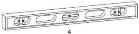
natural_image
Technical line drawing of a rectangular electronic component with four internal slots and a central slot, labeled '4' (no text or symbols on the diagram itself)
natural_image
Line drawing of a pair of gloves with different banding and stitching details (no text or symbols)
natural_image
Two wrench illustrations labeled 5 and 6, shown in side-by-side line drawings without any text or symbols.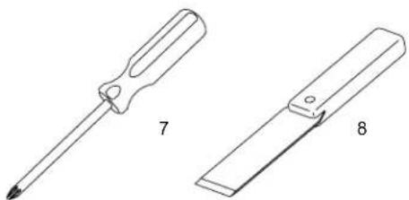
natural_image
Two technical illustrations of screwdrivers, labeled 7 and 8, showing different types of tool tips (no text or symbols beyond labels)LAS ILUSTRACIONES NO ESTAN A ESCALA
natural_image
Line drawing of two hands holding a flatboard with a device, no text or symbols presentnatural_image
Technical line drawing of an electrical enclosure or enclosure with internal components and wiring (no text or symbols)FRR053
Figura 29
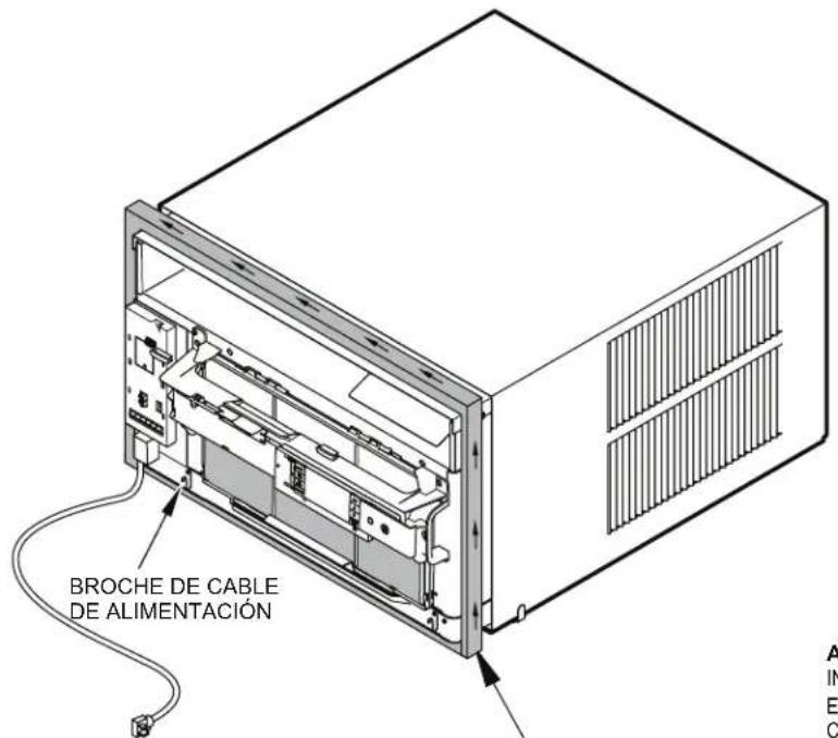
natural_image
Technical line drawing of a structural frame with labeled dimensions A and B (no text or symbols beyond labels)| Tabla 4 | |||
| DIMENSIONES TERMINADAS | CHASIS CHICO | CHASIS MEDIANO | CHASIS GRANDE |
| A 16 | 316" 18 | 316" 20 | 38" |
| B 26 | 316" 26 | 316" 28 | 14" |
| Aviso: Estas medidas son para el tamaño final de la abertura | |||
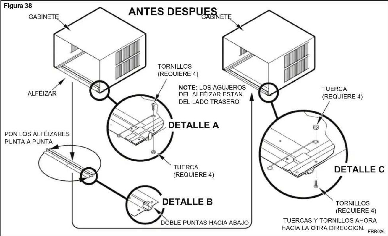
flowchart
graph TD
    A["Figura 38"] --> B["GABINETE"]
    B --> C["ALFÉIZAR"]
    C --> D["PON LOS ALFÉIZARES PUNTA A PUNTA"]
    D --> E["TORNILLOS (REQUIERE 4)"]
    E --> F["NOTE: LOS AGUJEROS DEL ALFÉIZAR ESTAN DEL LADO TRASERO"]
    F --> G["TUERCA (REQUIERE 4)"]
    G --> H["DETALLE A"]
    H --> I["TUERCA (REQUIERE 4)"]
    I --> J["DETALLE B"]
    J --> K["DOBLE PUNTAS HACIA ABAJO"]
    K --> L["TORNILLOS (REQUIERE 4)"]
    L --> M["TUERCAS Y TORNILLOS AHORA HACIA LA OTRA DIRECCION. FRR026"]
Figura 39
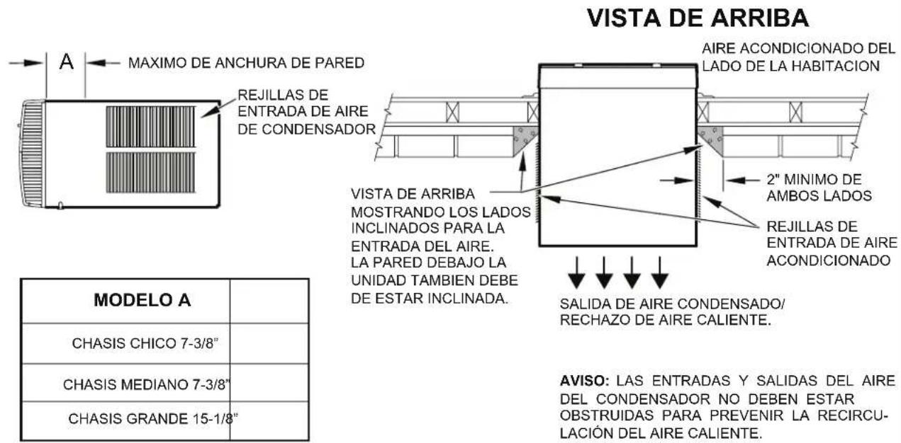
text_image
VISTA DE ARRIBA AIRE ACONDICIONADO DEL LADO DE LA HABITACION 2" MINIMO DE AMBOS LADOS REJILLAS DE ENTRADA DE AIRE ACONDICIONADO VISTA DE ARRIBA MOSTRANDO LOS LADOS INCLINADOS PARA LA ENTRADA DEL AIRE. LA PARED DEBAJO LA UNIDAD TAMBEN DEBE DE ESTAR INCLINADA. SALIDA DE AIRE CONDENSADO/ RECHAZO DE AIRE CALIENTE. MODELO A CHASIS CHICO 7-3/8" CHASIS MEDIANO 7-3/8" CHASIS GRANDE 15-1/8" AVISO: LAS ENTRADAS Y SALIDAS DEL AIRE DEL CONDENSADOR NO DEBEN ESTAR OBSTRUIDAS PARA PREVENIR LA RECIRCULACIÓN DEL AIRE CALIENTE.FRR027
Figura 40
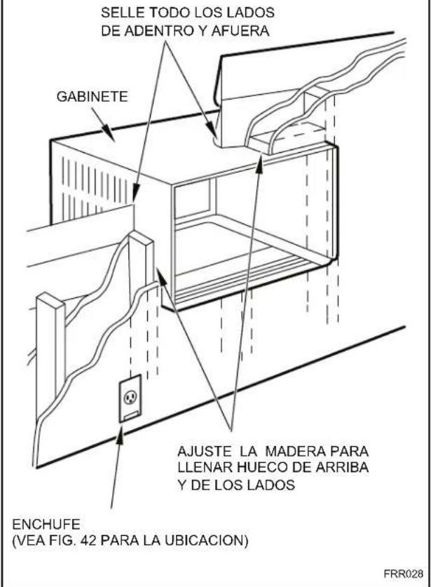
text_image
SELLE TODO LOS LADOS DE ADENTRO Y AFUERA GABINETE AJUSTE LA MADERA PARA LLENAR HUECO DE ARRIBA Y DE LOS LADOS ENCHUFE (VEA FIG. 42 PARA LA UBICACION) FRR028Figura 41
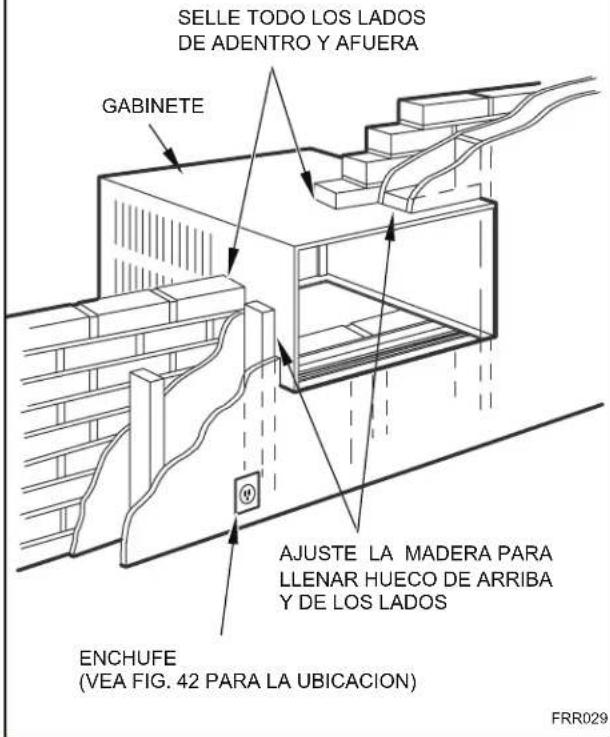
text_image
SELLE TODO LOS LADOS DE ADENTRO Y AFUERA GABINETE AJUSTE LA MADERA PARA LLENAR HUECO DE ARRIBA Y DE LOS LADOS ENCHUFE (VEA FIG. 42 PARA LA UBICACION) FRR029Figura 42
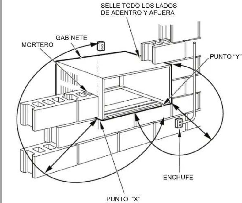
text_image
SELLE TODO LOS LADOS DE ADENTRO Y AFUERA MORTERO GABINETE PUNTO "Y" PUNTO "X" ENCHUFE| From Point "X" Chico/Mediano Grande | |
| 115V 69" N/A | |
| 230V 45" 45" | |
| From Point "Y" Chico/Mediano Grande | |
| 115V 45" N/A | |
| 230V 21" 20" | |
FRR030
Friedrich Air Conditioning Company
10001 Reunion Place, Suite 500
San Antonio, Tx 78216
1-800-541-6645
www.friedrich.com
natural_image
Line drawing of a white air conditioner unit with ventilation grilles and control panel (no text or symbols)Kühl 115-Volts: SS08M10, SS10M10, SS12M10, SS14M10 208-230-Volts: SS12M30, SS15M30, SM18M30, SM21M30 SM24M30, SL28M30, SL36M30
text_image
Figure 2 FRR071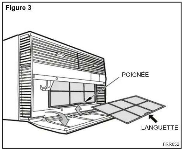
text_image
Figure 3 POIGNÉE LANGUETTE FRR052natural_image
Technical line drawing of a dual-panel storage unit with no text or symbolsFRR051FRR050
CETTE PAGE EST LAISSÉE VIDE INTENTIONNELLEMENT
text_image
Figure 13 FRR008natural_image
Line drawing of a handheld electric drill with two labeled parts (1 and 2), no text or symbols present.
natural_image
Technical line drawing of a rectangular electronic component with four internal slots and a labeled section (no text or symbols)
natural_image
Line drawing of a pair of gloves with different banding and stitching details (no text or symbols)
natural_image
Two types of wrenches labeled 5 and 6, shown side by side without any text or symbols on the tools themselves.
natural_image
Two technical line drawings of screwdrivers, labeled 7 and 8, showing different end caps (no text or symbols beyond labels)natural_image
Line drawing of two hands holding a flatboard with a device, no text or symbols presentSUPPORT DU PANNEAU DE COMMANDES
FRR012
text_image
ACHES. B B
text_image
BAS DU CHÂSSIS DE FENÊTRE JOINT EN VINYLE PROFILÉ SUPÉRIEUR SECTION B-BFRR023
text_image
Technical diagram of an electrical enclosure with labeled components and directional arrowFRR053
Figure 29
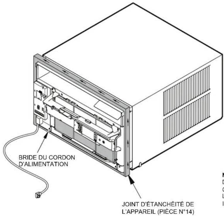
text_image
BRIDE DU CORDON D'ALIMENTATION JOINT D'ÉTANCHÉITÉ DE L'APPAREIL (PIÈCE N°14)NOTE : LORS DE L'INSTALLATION DU JOINT D'ÉTANCHÉITÉ, COMMENCER À L'UN DES COINS INFÉRIEURS, PUIS FAIRE LE TOUR PAR LE DESSUS DE L'APPAREIL JUSQU'AU COIN INFÉRIEUR OPPOSÉ.
FRR024
CETTE PAGE EST LAISSÉE VIDE INTENTIONNELLEMENT
natural_image
Technical line drawing of a structural frame with labeled dimensions A and B (no text or symbols beyond labels)| Tableau 4 | |||
| DIMENSIONS FINALES | PETIT FORMAT | FORMAT MOYEN | GRAND FORMAT |
| A | 41,1 cm (16 3/16 po) | 46,2 cm (18 3/16 po) | 51,7 cm (20 3/8 po) |
| B | 66,5 cm (26 3/16 po) | 66,5 cm (26 3/16 po) | 71,7 cm (28 1/4 po) |
| Note : Ces chiffres représentent les dimensions finales de l'ouverture. | |||
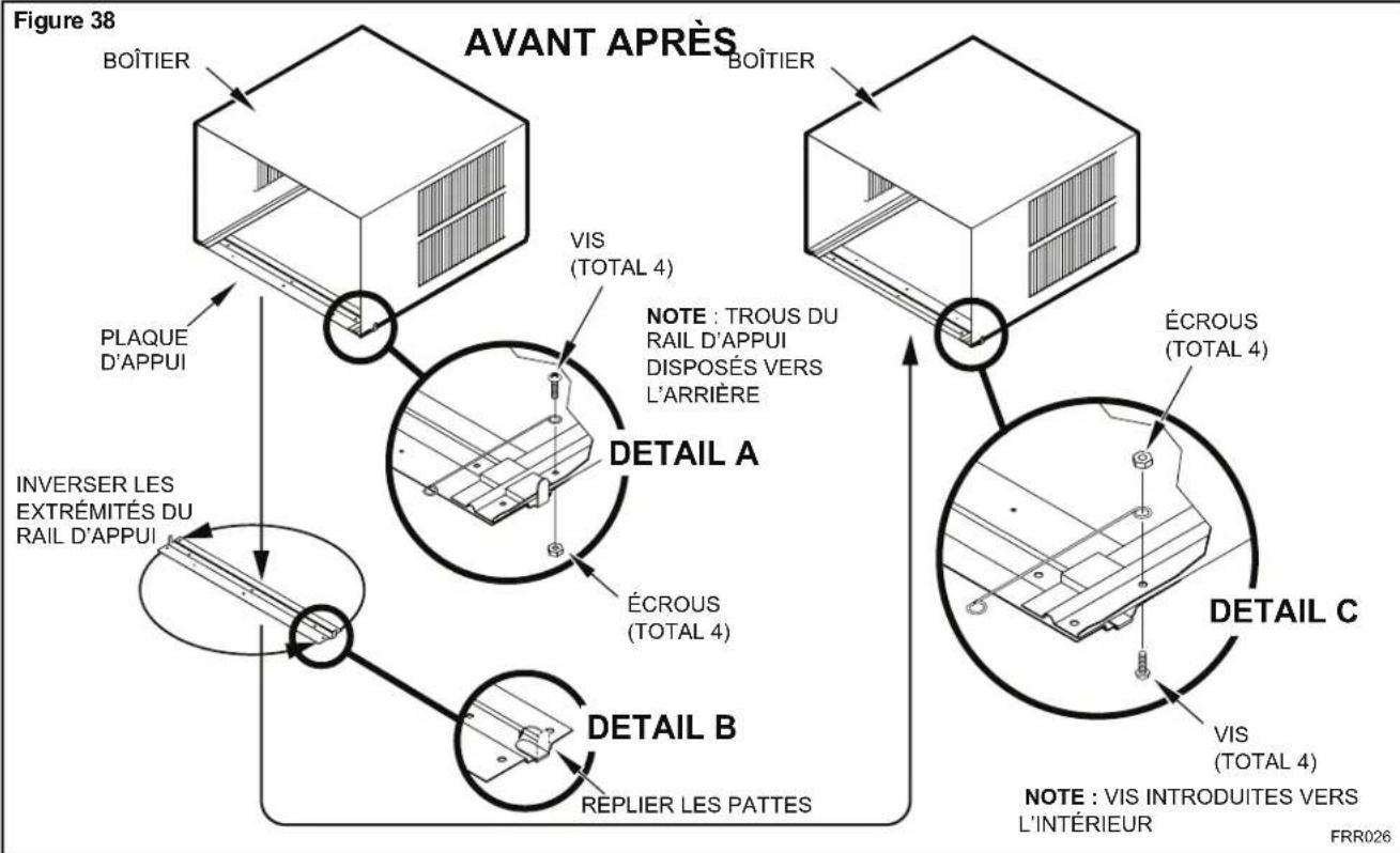
flowchart
graph TD
    A["BOÎTIER"] -->|PLAQUE D'APPUI| B["DETAIL A"]
    B -->|INVERSER LES EXTRÉMITÉS DU RAIL D'APPUI| C["DETAIL B"]
    C -->|REPLIER LES PATTES| D["DETAIL C"]
    D -->|NOTE : TROUS DU RAIL D'APPUI DISPOSÉS VERS L'ARRIÈRE| E["VOIC"]
    E -->|VIS (TOTAL 4)| F["AVANT APRÈS"]
    F -->|BOÎTIER| G["BOÎTIER"]
    G -->|ÉCROUS (TOTAL 4)| H["DETAIL C"]
    H -->|VIS (TOTAL 4)| I["EXTRÈMITÉS DU RAIL D'APPUI"]
    I -->|INVERSER LES EXTRÉMITÉS DU RAIL D'APPUI| J["DETAIL A"]
    J -->|ÉCROUS (TOTAL 4)| K["DETAIL C"]
    K -->|NOTE : VIS INTRODUITES VERS L'INTÉRIEUR| L["FRR026"]
Figure 39
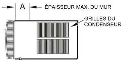
text_image
ÉPAISSEUR MAX. DU MUR GRILLES DU CONDENSEUR| MODELE A | |
| PETIT 7-3/8" | |
| MOYEN 7-3/8" | |
| GRAND 15-1/8" |
VUE DE DESSUS
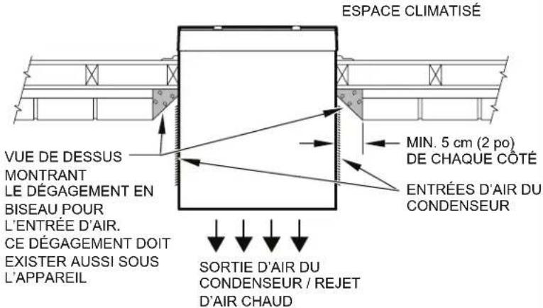
text_image
ESPACE CLIMATISÉ VUE DE DESSUS MONTRANT LE DÉGAGEMENT EN BISEAU POUR L'ENTRÉE D'AIR. CE DÉGAGEMENT DOIT EXISTER AUSSI SOUS L'APPAREIL MIN. 5 cm (2 po) DE CHAQUE COTÉ ENTRÉES D'AIR DU CONDENSEUR SORTIE D'AIR DU CONDENSEUR / REJET D'AIR CHAUDNOTE : LES ENTRÉES ET SORTIES D'AIR DU CONDENSEUR DOIVENT ÊTRE PARFAITEMENT DÉGAGÉES POUR ÉVITER UNE RECIRCULATION DE L'AIR CHAUD REJETÉ.
FRR027
Figure 40
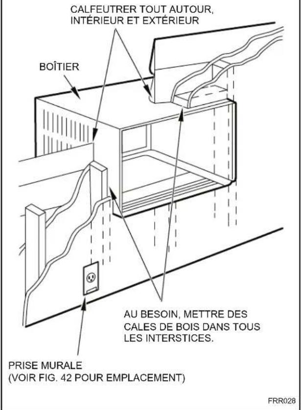
text_image
CALFEUTRER TOUT AUTOUR, INTÉRIEUR ET EXTÉRIEUR BOÎTIER AU BESOIN, METTRE DES CALES DE BOIS DANS TOUS LES INTERSTICES. PRISE MURALE (VOIR FIG. 42 POUR EMPLACEMENT) FRR028Figure 41
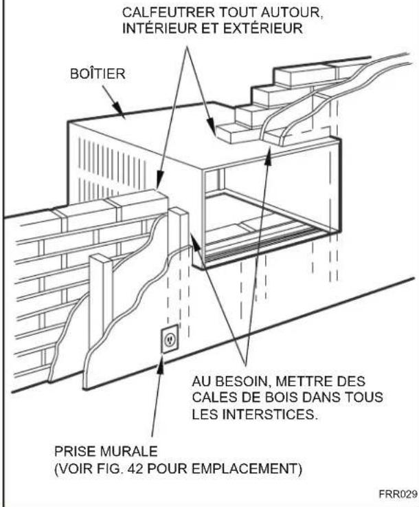
text_image
CALFEUTRER TOUT AUTOUR, INTÉRIEUR ET EXTÉRIEUR BOÎTIER AU BESOIN, METTRE DES CALES DE BOIS DANS TOUS LES INTERSTICES. PRISE MURALE (VOIR FIG. 42 POUR EMPLACEMENT) FRR029Figure 42
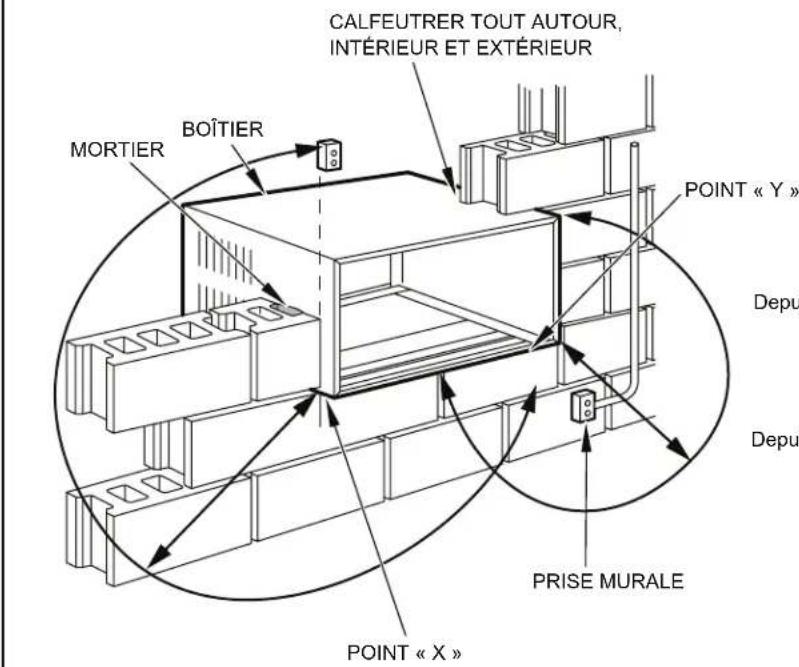
Friedrich Air Conditioning Company
10001 Reunion Place, Suite 500
San Antonio, Tx 78216
1-800-541-6645
www.friedrich.com