Hazardgard SH20M30B - Air Conditioning Friedrich - Free user manual and instructions
Find the device manual for free Hazardgard SH20M30B Friedrich in PDF.

User questions about Hazardgard SH20M30B Friedrich
0 question about this device. Answer the ones you know or ask your own.
Ask a new question about this device
Download the instructions for your Air Conditioning in PDF format for free! Find your manual Hazardgard SH20M30B - Friedrich and take your electronic device back in hand. On this page are published all the documents necessary for the use of your device. Hazardgard SH20M30B by Friedrich.
USER MANUAL Hazardgard SH20M30B Friedrich
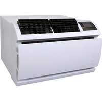
Hazardous Location Room Air Conditioner
natural_image
Line drawing of a portable air conditioner unit with ventilation grilles and control panel (no text or symbols)Equipment is certified in accordance with:
ISA 12.12.01 and NFPA 70-10
(National Electric Code)
Article 501 ATEX*
Class I, Div. 2 Groups A,B,C,& D II 3 G Ex ec nA nC IIC T4G
DEMKO 15 ATEX 1364X
Article 505 IECEx*
Class I, Zone 2, Groups IIA IIB + H and IIC Ex ec nA nC IIC T Gc IECEx UL15.0051X
8^ C ≤ Tamb ≤ 55^ C
240/220 V, 50 HZ: SH20*
230/208V, 60 HZ; SH15, SH20, SH24*
Table of Contents
Operation and Care Instructions
Your Safety and the safety of others....2
General Instructions....3
Filter Information 4
Special Features 5
Control Panel....5
Underwriters Laboratories 6
Installation Instructions
Electrical Requirements....7
Installation Hardware 8
Unpacking the Unit....9-10
Outdoor / Indoor Clearances....11
Through-the-Wall 12-14
Sash Window 15-20
Chassis Wiring and Preparation 21-24
Chassis Installation 25-26
Maintenance Checklist....27
WARRANTY....28
| WARNING | ADVERTENCIA | AVERTISSEMENT | |
| THINK SAFETY FIRST | Do not remove, disable or bypass this unit's safety devices. Doing so may cause, fire, injuries or death. | No eliminar, desactivar o pasar por alto los dispositivos de seguridad de la unidad. Si lo hace podría producirse fuego, lesiones o muerte. | Ne pas supprimer, désactiver ou contourner cette l'unité des dispositifs de sécurité. Faire vous risqueriez de provoquer, le feu, les blessures ou la mort. |
| Do not open when an explosive atmosphere is present. | No abra cuando se encuentre en una atmósfera explosiva. | Ne pas ouvrir lorsque une atmosphère explosive est présente. | |
| Do not separate when energized. | No separar cuando se encuentre bajo tensión. | Ne pas séparer sous tension. | |
| To avoid the buildup of electrostatic charge, regularly clean the unit with a damp cloth. paño | Para evitar la acumulación de cargas electrostáticas, limpie regularmente la unidad con un húmedo. | Pour éviter l'accumulation de charges électrostatiques, nettoyer régulièrement l'appareil avec un chiffon humide. |
Congratulations!
Thank you for your decision to purchase the Friedrich Hazardgard (Hazardous Duty Room Air Conditioner). Your new Friedrich has been carefully engineered and manufactured to give you many years of dependable, efficient operation, maintaining a comfortable temperature and humidity level. Many extra features have been built into your unit to assure quiet operation, the greatest circulation of cool, dry air, and the most economic operation.
General Instructions
This Installation and Operation Manual has been designed to insure maximum satisfaction in the performance of your unit. For years of trouble-free service, please follow the installation instructions closely. We cannot overemphasize the importance of proper installation. We have added new information to the basic instructions to help you achieve proper installation.

WARNING
Refrigeration system under high pressure.
Do not puncture, heat, expose to flame or incinerate.
Only certified refrigeration technicians should service this equipment.
R410A systems operate at higher pressures than R22 equipment. Appropriate safe service and handling practices must be used.
Only use gauge sets designed for use with R410A. Do not use standard R22 gauge sets.

WARNING
Please read this manual thoroughly prior to equipment installation or operation.
It is the installer's responsibility to properly apply and install the equipment. Installation must be in conformance with the NFPA 70-2008 National Electric Code or current edition, International Mechanic Code 2009 or current edition and any other applicable local or national codes.
Failure to do so can result in property damage, personal injury or death.
Here are some suggestions to help you use your new Friedrich most efficiently:
- Carefully read and follow the installation instructions.
- Make sure the unit is the right capacity for the area to be cooled. An undersized unit makes the unit work too hard, using more electricity than needed and increases wear. An oversized unit will cycle on and off too rapidly, and therefore cannot control humidity very well.
-
When you first turn on your Friedrich, set the thermostat to its coldest position to cool the room. When the desired temperature is reached, turn the thermostat control toward the "warmer" position until you hear a click and the compressor goes off. The thermostat will then cycle the compressor to maintain the selected temperature.
-
Clean the filter frequently (See Filter Information)
-
Do not block the air flow to and from the unit. Make sure the louvers are directed to give even distribution of air throughout the room. Caution: If air directed into a restricted area such as a corner, this may cause the unit to cycle on and off rapidly, which could damage your unit.
-
A dirty filter or improperly set controls can affect the cooling ability of the unit.
-
If cooling is weak and you have verified that the filter is clean and the controls are properly set, the unit may be low on refrigerant, and you should call your Friedrich service provider to check the unit.
-
Keep blinds, shades and drapes closed on the sunny side of the room being cooled.
-
Proper room insulation helps your unit maintain the desired inside temperature.
- Whenever possible, shade west-facing windows with awnings, trees, or window tinting.
- Keep window treatments away from the unit to provide free air flow.
Your safety and the safety of others are very important.
We have provided many important safety messages in this manual and on your appliance. Always read and obey all safety messages.

This is a safety Alert symbol. This symbol alerts you to potential hazards that can kill or hurt you and others.
All safety messages will follow the safety alert symbol with the word "WARNING" or "CAUTION". These words mean:
WARNING
Indicates a hazard which, if not avoided, can result in severe personal injury or death and damage to product or other property.
CAUTION
Indicates a hazard which, if not avoided, can result in personal injury
and damage to product or other property.
All safety messages will tell you what the potential hazard is, tell you how to reduce the chance of injury, and tell you what will happen if the instructions are not followed.
NOTICE
Indicates property damage can occur if instructions are not followed
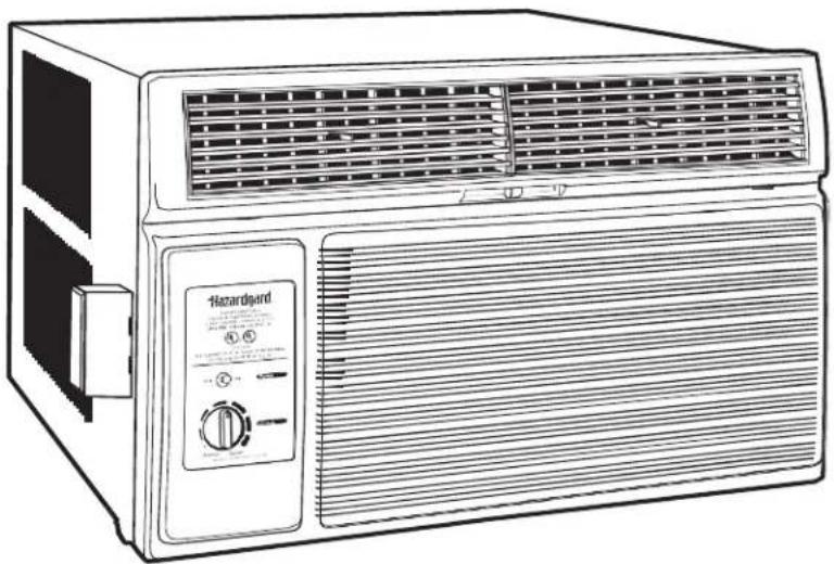
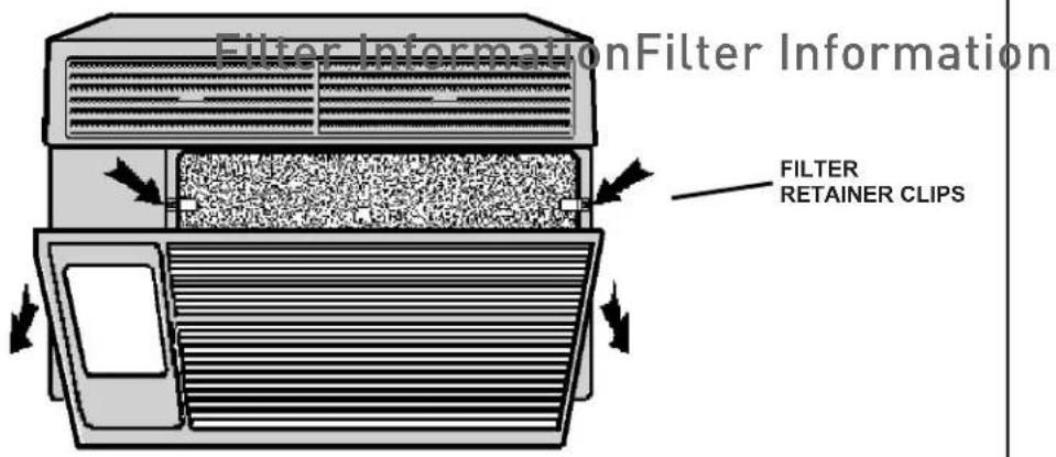
Filter Information
The filter in your Friedrich removes dust, pollen and other impurities from the air as they are drawn through the unit. The filter is permanent and reusable, and has a germicidal treatment which is not affected by periodic washing.
A clogged, dirty filter reduces the air flow through the unit and reduces its efficiency. You should check the filter every seven to ten days, depending on the amount your unit is used. Clean the filter regularly
Figure 1
text_image
Filter Information Filter Information FILTER RETAINER CLIPSThe filter can be removed for cleaning by opening the front of the unit and releasing the filter from its retaining clips.
Hazardgard Special Features
- Permanent Split-Capacitor, totally enclosed fan motor to assure efficient operation even under adverse conditions.
- Motor has a special stainless steel shaft to resist corrosion and a hermetically sealed overload for arc-free operation.
- High capacity compressor with internal hermetically sealed overload.
- Contains transient voltage suppressor to protect controls against transient voltage spikes. Provides solid state switches for arc-free operation.
- Hot gas bypass low ambient control to permit operation without freezing at outdoor ambient temperatures as low as 45°F (7°C).
- IP44 Environmentally sealed electrical components protect against ingress of moisture (ATEX & IECEx)
- Polyester powder finish, oven-baked for an attractive, long-lasting finish
• Copper tubing/aluminum hydrophilic coated fin coils
ctrical
• Galvanized steel cabinet and base pan, all bonderized.
- Slide-out chassis for easy installation in window or through-the-wall.
- Extra insulation inside, including completely insulated plenum chamber for quieter, more efficient cooling.
- Entire unit test run in environmental chamber before crating.
• Eight-way air flow control for uniform circulation
- Condensate drain with exclusive mosquito trap.
- 15amp or 20amp circuit with time-delay fuse required. Accommodates direct wiring.
- Long lasting 3/8" (10mm) thick air filter, germicidally treated, easily removed for cleaning
Friedrich Air Conditioning quality has been proven by more than 30 years of successful experience from the Gulf of Mexico to the searing sands of the Arabian Desert.
Control Panel
Function Control (Power)
This switch is a double pole, single throw toggle switch.
ON - Turns everything on.
OFF - Turns everything off.

POWER MUST BE DISCONNECTED AT CIRCUIT BREAKER/FUSE BEFORE SERVICING!
Temperature Control
The knob at the bottom is the thermostat which is a cross ambient type used to maintain the desired comfort level. The thermostat reacts only to a change in temperature at the bulb location - turn the knob clockwise to set cooler, counter- clockwise for warmer.
Friedrich leads with the first UL Listed Room Air Conditioners designed to cool living quarters and other enclosures situated in hazardous locations where specific volatile flammable liquids or gases are handled or used with enclosed containers or systems.
Friedrich Hazardgard room air conditioners are designed to meet the National Electrical Code, Article 500 requirements for Class I, Division 2, Groups A,B,C,D Hazardous locations, CERTIFIED BY UNDERWRITERS LABORATORIES FOR USE IN CLASS 1, DIVISION 2, GROUPS A,B,C,D HAZARDOUS LOCATIONS.
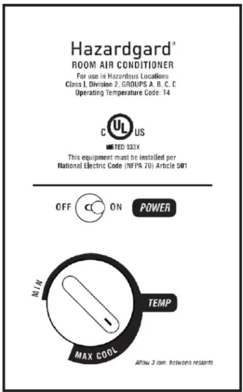
text_image
Hazardgard® ROOM AIR CONDITIONER For use in Hazardous Locations Class I, Division 2, GROUPS A. B. C. C. Operating Temperature Code: T4 C UL US LISTED 933X This equipment must be installed per National Electric Code (NFPA 70) Article 501 OFF ON POWER MIN TEMP MAX COOL Allow 3 min. between restartsATEX & ICEX Standards Specific to Models SH20N50AT & SH24N30AT
SH20N50AT and SH24N30AT Adhere to the following certifications:
CERTIFIED PER STD. NO. ANSI/ISA 12.12.01,2013
PER STD. NO. IEC 60079-0, 6th Edition PER STD. NO. IEC 60079-15, 4th Edition
PER STD. NO. CAN/CSA C22.2 NO. 213-M1987
PER STD. NO. CENELEC EN 60079-0: 2012 + A11: 2013
PER STD. NO. CENELEC EN 60079-15: 2010
CERTIFICATION DEMKO 15 ATEX 1364X II 3 G Ex ec nA nC IIC T4 Gc IECEX UL15.0051X DEMKO 15 ATEX 1364X
SH20N50AT & SH24N30AT
Specific Conditions of Use:
- Provision shall be made to prevent the rated voltage being exceeded by the transient disturbances of more than 140% of the peak rated voltage.
- The equipment must be installed only for use in locations providing adequate protection against the entry of solid foreign objects or water capable of impairing safety.
- Only permanently wired cables may enter the cable glands. The user shall provide for the required strain relief.
- Degree of protection will be safeguarded only when sealing and cable entry fittings are properly fitted. To ensure proper protection, all wiring connections and conduit passageways must have the appropriate ATEX/IECEx certified plug or cable gland.
- Cable Glands shall be mounted into the enclosure in such a way that they are mechanically protected against impact force.
- To avoid the buildup of electrostatic charge, regularly clean the unit with a damp cloth.
- The appliance is not to be used by persons (including children) with reduced physical, sensory or mental capabilities, or lack of experience and knowledge, unless they have been given supervision or instruction. Children to be supervised not to play with the appliance.
- The enclosure with a coating must not be used in areas affected by charge-producing processes, mechanical friction and separation process, electron emission (e.g. in the vicinity of electrostatic coating equipment), and pneumatically conveyed dust.
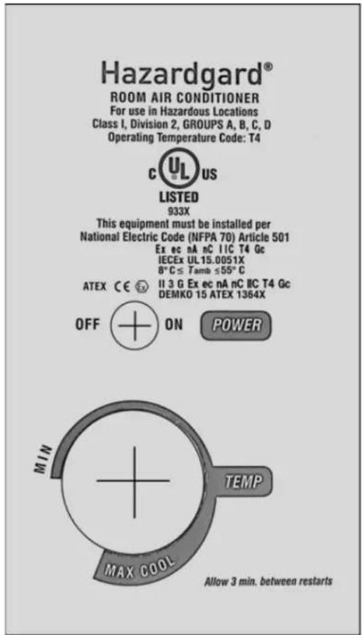
text_image
Hazardgard® ROOM AIR CONDITIONER For use in Hazardous Locations Class I, Division 2, GROUPS A, B, C, D Operating Temperature Code: T4 UL US LISTED 933X This equipment must be installed per National Electric Code (NFPA 70) Article 501 Ex ec nA nC IIC T4 Gc IECEx UL15.0051X 8°C ≤ Tamb ≤55°C ATEX CE II 3 G Ex ec nA nC IIC T4 Gc DEMKO 15 ATEX 1364X OFF ON POWER MIN TEMP MAX COOL Allow 3 min. between restartsNOTICE: To maintain IP44 protection, the Hazardgard unit must be installed in accordance to the installation instructions stated in this document.
| The following additional previous editions of Standards noted under the "Standards" section of this Certificate where applied to integral Components as itemized below. There are no significant safety related changes between these previous editions and the editions noted under the "Standards" section. | |
| Junction Box, Part No. 25. 10 16 08, manufactured by Rose. | IEC 60079-7:2006-07, IEC 60079-31: |
Electrical Ratings:
| ATEX/IECEx Model Number R | Rated Voltage, Frequency | Rated Cooling Amps | Compressor RLA,LRA | Motor FLA | Motor HP | MCA MOP | |
| SH20N50AT 240/220, 50Hz 11 | .6 9.4, 50 2 1/3 13.25 | 20 | |||||
| SH24N30AT | 230/208, 60 Hz | 11.8 | 10.2, 52 | 1.5 | 1/4 | 14.25 | 20 |
Refrigerant System Ratings:
| ATEX/IECEx Model Number | R-410a Charge, oz | High-Side Design Pressure (PSIG) | Low-Side Design Pressure (PSIG) |
| SH20N50AT-B | 40.7 | 600 | 300 |
| SH24N30AT-A | 46.8 | 600 | 300 |
Installation Instructions Models SH15, SH20 and SH24
NOTE: THIS MANUAL INCLUDES INSTALLATION INSTRUCTIONS FOR BOTH WINDOW MOUNT AND THROUGH- THE WALL INSTALLATIONS
WARNING

Explosion Hazard

Electrical Shock Hazard
Electrically connect unit in accordance with NEC Code Article 501. Failure to do so can result in death, explosion, fire or electrical shock
Electrical Requirements
ALL FIELD WIRING MUST MEET THE REQUIREMENTS OF THE NATIONAL ELECTRICAL CODE (ANSI/NFPA 70) ARTICLE 501.
THE FIELD-PROVIDED CIRCUIT PROTECTION DEVICE (HACR CIRCUIT BREAKER OR TIME DELAY FUSE) MUST NOT EXCEED THE AMPACITY INDICATED ON THE PRODUCT NAMEPLATE.
IMPORTANT: Before you begin the actual installation of your air conditioner, check local electrical codes and the information below. Your power supply must be the same A.C. voltage and frequency (hertz) as marked on the name plate located on the chassis. Only alternating current (A.C.), no direct current (D.C.), can be used.
An overloaded circuit will invariably cause malfunction or failure of the air conditioner; therefore, it is extremely important that the electrical power is adequate. Consult your dealer or power company if in doubt.
The following instructions are for HAZARDGARD models and cabinet sizes listed below.
| GROUPS CABINET SIZE (H x W X D) | |
| SMALL CHASSIS SH15 15 15/16" x | 25 15/16" x 27 3/8"(405 mm x 660 mm x 695 mm) |
| MEDIUM CHASSIS SH20, SH 24 17 | 15/16" x 25 15/16" x 27 3/8"(455 mm x 660 mm x 695 mm) |
| Model Number Plug Type Circuit Rating | Time Delay Fuse |
| SH15 Junction Box 250V-15 Amp | |
| SH20, SH24 Junction Box 250V-20 Amp |
Window Mount Installation Hardware
| ITEM No. | DESCRIPTION QTY. | |
| SHELL MOUNTING PARTS | ||
| 1 | SUPPORT BRACKET 2 | |
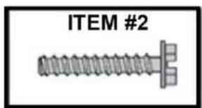
| 2 | SCREW, 10 - 24 x 1" HEX HEAD 4 | |
| 3 | 10 - 24 FLAT WELDNUT 4 | |
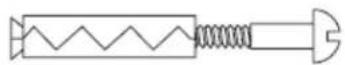
| 4 | SCREW, SHEET METAL #12A x 2" 7 | |
| WINGBOARD ANGLE MOUNTING | ||
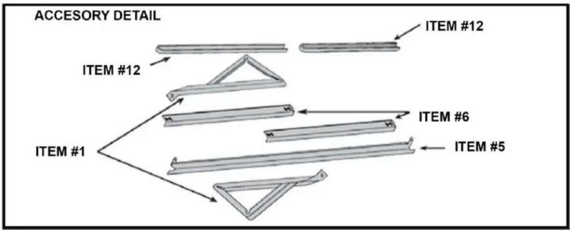
| 5 | WINGBOARD ANGLE, TOP 1 | |
| 6 | WINGBOARD ANGLE, SIDE 2 | |
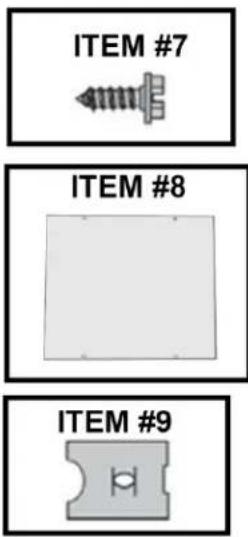
| 7 | SCREW, SHEET METAL #8A x 3/8" 2 | |
| WINGBOARD MOUNTING PARTS | ||
| 8 | WINGBOARD (MASONITE) 1 | |
| 9 | J TYPE SPEED NUT 4 | |
| 10 | WINGBOARD CLIP (SPRING STEEL) | 4 |
| 11 | SCREW. #8A x 1/2" PHILLIPS TRUSS HD. | 4 |
| WINDOW SEALING | ||
| 12 | WINDOW SEAL GASKET (DARK FOAM) | 1 |
text_image
ITEM #2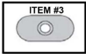
text_image
ITEM #3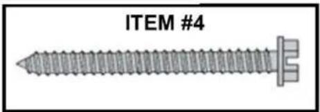
text_image
ITEM #4ITEM #5 SEE ACCESSORY DETAIL IMAGE
ITEM #6 SEE ACCESSORY DETAIL IMAGE
text_image
ITEM #7 ITEM #8 ITEM #9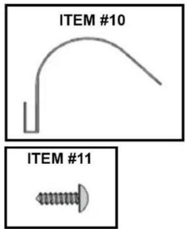
text_image
ITEM #10 ITEM #11ITEM #12 SEE ACCESSORY DETAIL IMAGE
flowchart
graph TD
    A["ITEM #1"] --> B["ITEM #6"]
    A --> C["ITEM #5"]
    A --> D["ITEM #12"]
    D --> E["ITEM #12"]
    style A fill:#f9f,stroke:#333
    style B fill:#ccf,stroke:#333
    style C fill:#ccf,stroke:#333
    style D fill:#cfc,stroke:#333
    style E fill:#fcc,stroke:#333
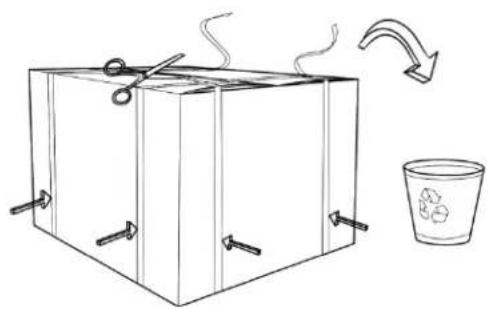
Unpacking The Unit
STEP 1 Cut the packing straps and remove box pulling it up, remove corner-post and protective packing, conserve the fiberboard wing board in a safe place, it will be used later.
Figure 2
natural_image
Simple line drawing of a box with scissors and a recycling cup, no text or symbols present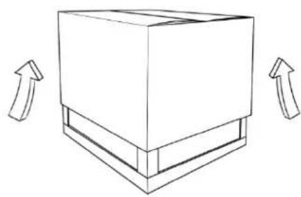
natural_image
Simple line drawing of a 3D box with two arrows indicating upward motion (no text or symbols)STEP 2 Remove decorative plastic return air grille to a safe area away from the unit.
STEP 3 Remove the installation hardware, two gaskets from beneath the unit, and place them in a safe area away from the unit.
Figure 3
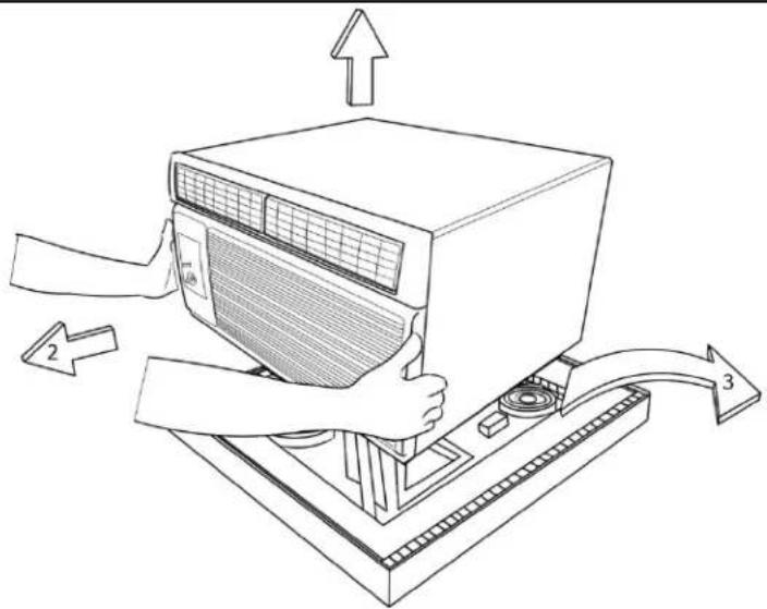
text_image
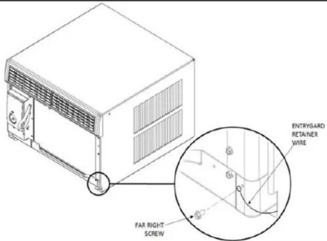
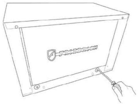
Diagram showing a computer monitor with labeled parts and directional arrows indicating process flowSTEP 4 Remove the chassis retainer by removing the far right screw in the basepan (see Figure 4); save this screw to reattach the chassis retainer after installation.
Figure 4
text_image
ENTRYGARD RETAINER WIRE FAR RIGHT SCREWUnpacking The Unit
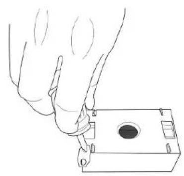
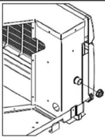
STEP 5 Remove and discard the two retainer screws and plastic bushings located at the rear of the unit. (Figure 5)
Figure 5
natural_image
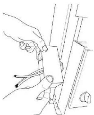
Line drawing of a mechanical device with a handle and screwdriver inserted, no text or symbols presentSTEP 6 While an assistant holds the cabinet stationary, use the hand pull at the front of the base pan (see Figure 6) to pull the chassis out of the cabinet.
Figure 6
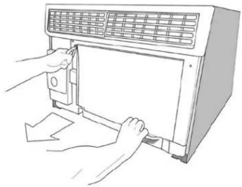
natural_image
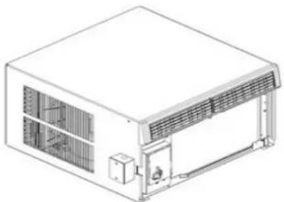
Line drawing of hands operating a microwave oven with a door panel (no text or symbols)STEP 7 Remove white foam blocks used to restrain the compressor during shipment (if included). Also remove junction box from under fan motor.
Figure 7
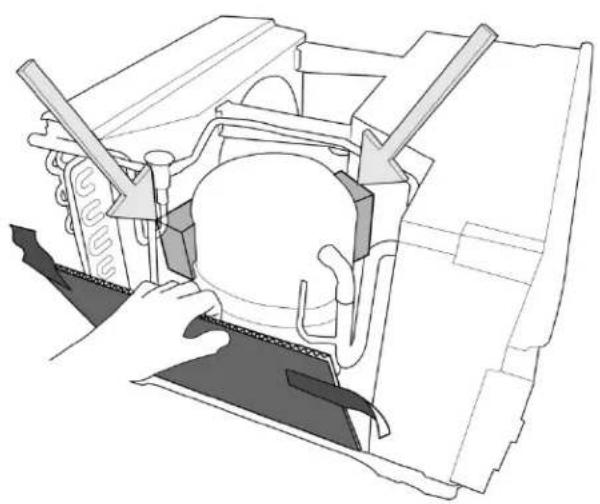
natural_image
Technical line drawing of a mechanical assembly with arrows indicating components (no text or symbols)
natural_image
Technical line drawing of a mechanical assembly with no visible text or symbolsInstallation: Outdoor/Indoor Clearances
Figure 8
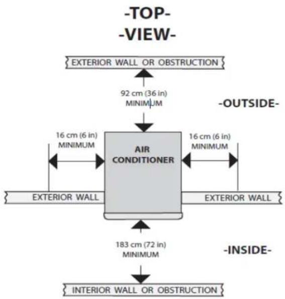
flowchart
graph TD
    A["EXTERIOR WALL OR OBSTRUCTION"] --> B["92 cm (36 in) MINIMUM"]
    B --> C["AIR CONDITIONER"]
    C --> D["16 cm (6 in) MINIMUM"]
    D --> E["EXTERIOR WALL"]
    C --> F["16 cm (6 in) MINIMUM"]
    F --> G["EXTERIOR WALL"]
    C --> H["183 cm (72 in) MINIMUM"]
    H --> I["INTERIOR WALL OR OBSTRUCTION"]
    style A fill:#f9f,stroke:#333
    style B fill:#ccf,stroke:#333
    style C fill:#cfc,stroke:#333
    style D fill:#fcc,stroke:#333
    style E fill:#cff,stroke:#333
    style F fill:#ffc,stroke:#333
    style G fill:#fcc,stroke:#333
    style H fill:#ffc,stroke:#333
    style I fill:#fcc,stroke:#333
Figure 9
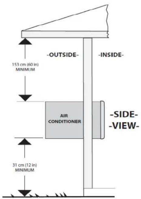
text_image
-OUTSIDE- -INSIDE- 153 cm (60 in) MINIMUM AIR CONDITIONER -SIDE- -VIEW- 31 cm (12 in) MINIMUMShell Installation: Through-the-wall Installations (as unit is shipped)

WARNING
Falling Object Hazard
Not following Installation Instructions for mounting your air conditioner can result in property damage, injury, or death.

Wall Preparation
The maximum wall thickness permissible without special construction is determined by the model size to be installed. THE OUT-SIDE CABINET CONDENSER AIR INTAKE LOUVERS MUST NOT BE BLOCKED BY EXTENDING INSIDE THE WALL AREA. Observe the maximum wall thickness shown as dimension "A" in (Figure 10).
Special Instructions For Extra Thick Walls
For installation in walls exceeding the maximum thickness shown as dimension A, the following suggested construction may apply. (See Figure 10).
Figure 10
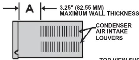
text_image
A 3.25" (82.55 MM) MAXIMUM WALL THICKNESS CONDENSER AIR INTAKE LOUVERS TOP VIEW SHOEXTRA THICKWALL CONSTRUCTION
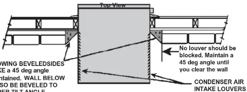
text_image
Top View NO Louver should be blocked. Maintain a 45 deg angle until you clear the wall LOWING BEVELEDSIDES LE a 45 deg angle contained. WALL BELOW SO BE BEVELED TO PER TILT ANGLE CONDENSER AIR INTAKE LOUVERSTOP VIEW SHOWING BEVELEDSIDES FOR AIR INTAKE a 45 deg angle should be maintained. WALL BELOW UNIT MUST ALSO BE BEVELED TO ASSURE PROPER TILT ANGLE.
STEP 1 CHECKING WIRING AND PLUMBING: Check all wiring and plumbing inside and outside the wall to be sure none will be broken where the hole is to be cut.
STEP 2 HOLE CONSTRUCTION: Depending on the size of the unit to be installed, layout the hole dimensions in accordance with the chart below (See Figure 11). Cut and frame in the hole to the finished dimensions. Use 2" x 4" material for framing and follow the suggested typical installations in (Figure 12, 13 or 14 on Page 13.
NOTE: IF THE WALL CONSTRUCTION IS TYPICAL FRAME OR 2 X 4 STUDDING WITH BRICK OR STONE VENEERS, LOCATE THE HOLE NEXT TO ONE OF THE STUDS. FOR MASONRY, CONCRETE OR CINDER BLOCK WALLS, LOCATE THE HOLE FOR CONVENIENCE.
Figure 11
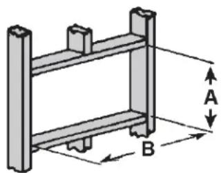
natural_image
Isometric diagram of a two-tiered structural frame with labeled dimensions A and B (no text or symbols beyond labels)HOLE SIZE REQUIREMENTS
| FINISHED DIMENSION | SH15 CHASSIS | SH20, SH24 CHASSIS |
| A 16-3/16" | 18-3/16" | |
| B 26-3/16" | 26-3/16" |
NOTE: THESE DIMENSIONS ARE FOR FINISHED HOLE SIZE
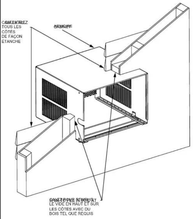
Figure 12 FRAME WALL CONSTRUCTION Figure 13 BRICK VENEER CONSTRUCTION
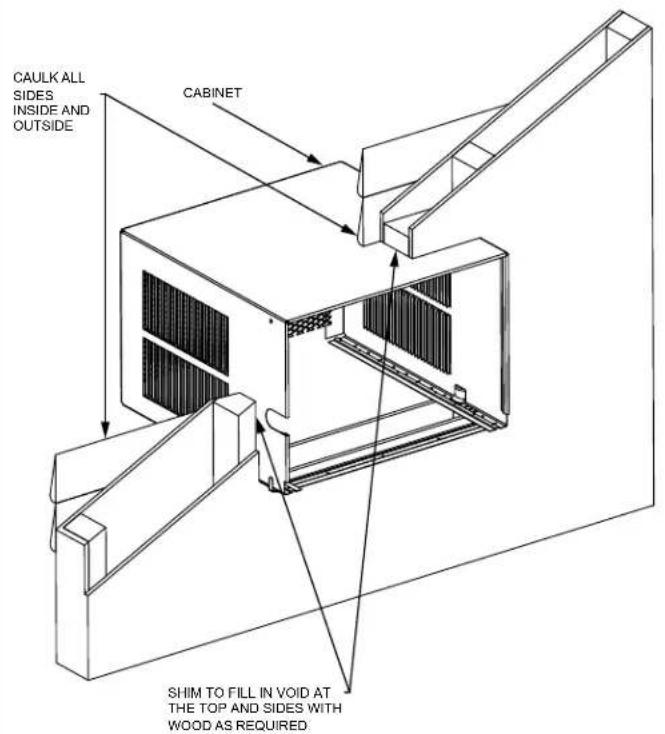
text_image
CAULK ALL SIDES INSIDE AND OUTSIDE CABINET SHIM TO FILL IN VOID AT THE TOP AND SIDES WITH WOOD AS REQUIRED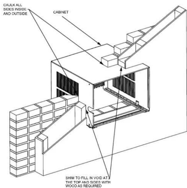
text_image
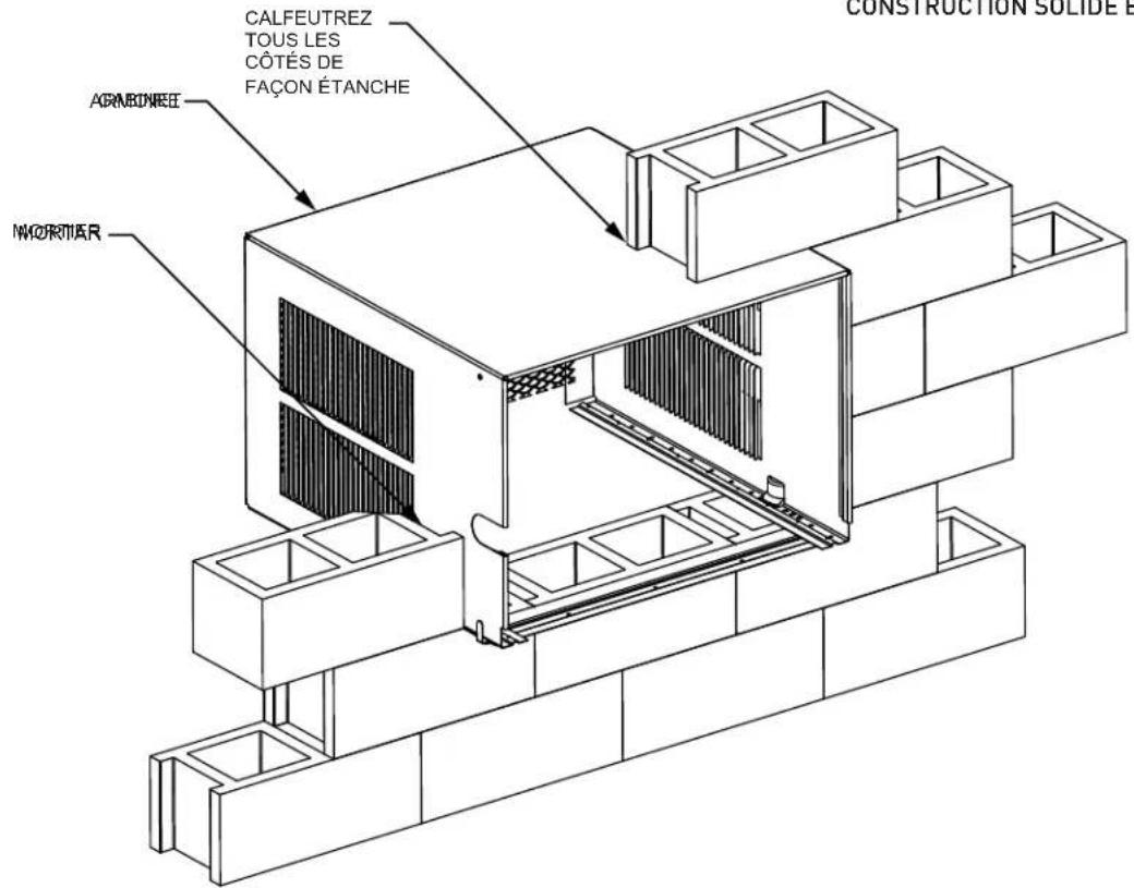
CAULK ALL SIDES INSIDE AND OUTSIDE CABINET SHIM TO FILL IN VOID AT THE TOP AND SIDES WITH WOOD AS REQUIREDFigure 14 SOLID MASONRY CONSTRUCTION
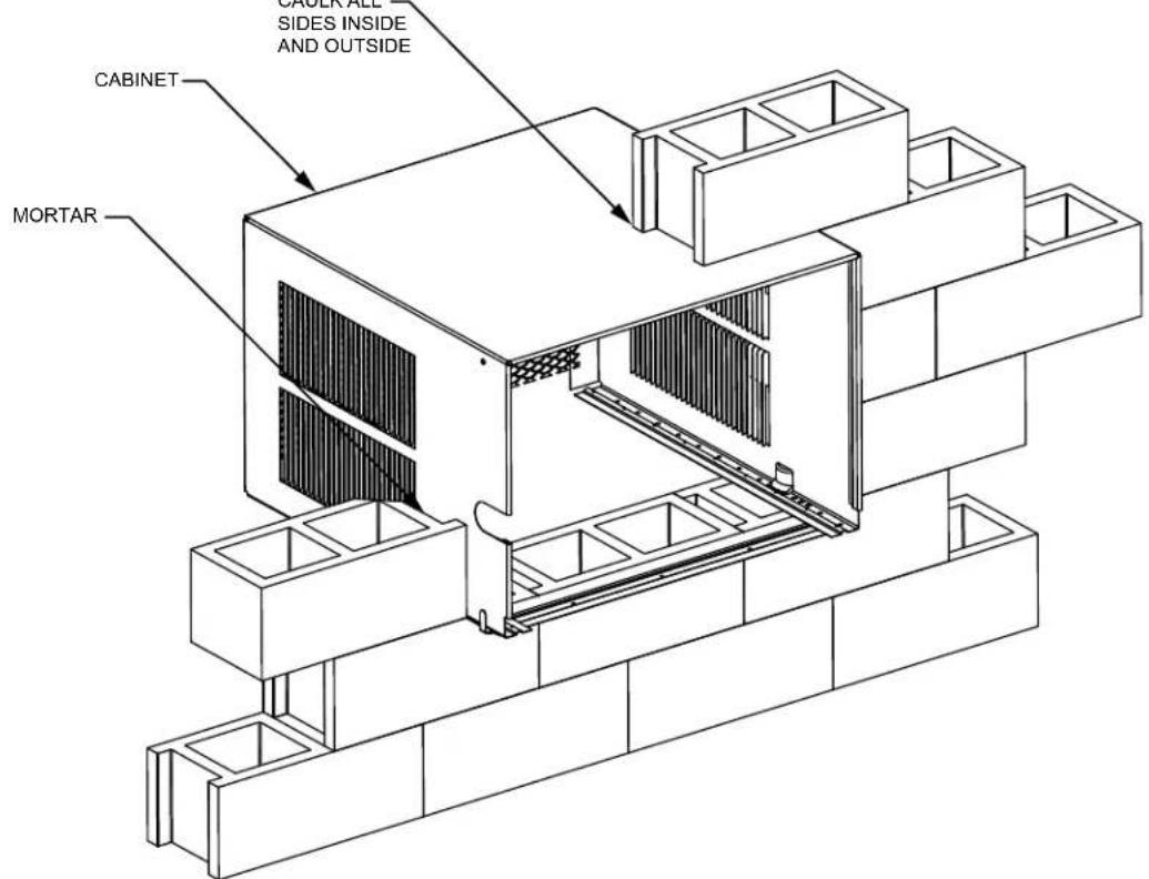
text_image
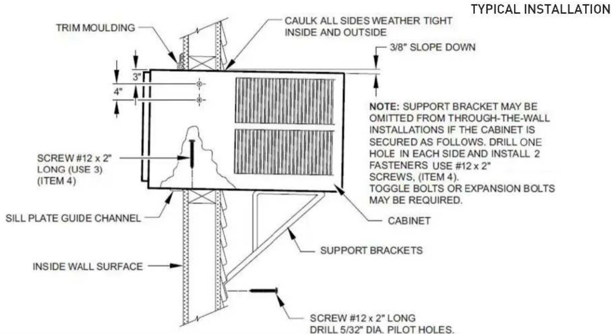
CABINET SIDESE INSIDE AND OUTSIDE MORTARSTEP 3 Slide the cabinet into the hole far enough to allow the guide-channel of the sill plate to contact the inside wall surface (See Figure 15).
STEP 4 Drill three (3) 5/32" diameter pilot holes through holes in sill-plate into the framing and install three (3) #12 x 2" long screws (Item #4) (See Figure15).
NOTICE
Instructions for mounting sleeve with slope must be observed to prevent entry of water into room. Potential property damage can occur if instructions are not followed.
Figure 15
text_image
TYPICAL INSTALLATION TRIM MOULDING CAULK ALL SIDES WEATHER TIGHT INSIDE AND OUTSIDE 3/8" SLOPE DOWN NOTE: SUPPORT BRACKET MAY BE OMITTED FROM THROUGH-THE-WALL INSTALLATIONS IF THE CABINET IS SECURED AS FOLLOWS. DRILL ONE HOLE IN EACH SIDE AND INSTALL 2 FASTENERS USE #12 x 2" SCREWS, (ITEM 4). TOGGLE BOLTS OR EXPANSION BOLTS MAY BE REQUIRED. Screw #12 x 2" LONG (USE 3) (ITEM 4) SILL PLATE GUIDE CHANNEL CABINET SUPPORT BRACKETS INSIDE WALL SURFACE SCREW #12 x 2" LONG DRILL 5/32" DIA. PILOT HOLES.NOTE: ALTERNATE FA STENERS WHICH MAY BE USED FOR SECURING THE SILL PL ATE IN THE WALL, AND THE SUPPORT BRACKETS TO THE OUTSIDE WALL ARE NOT FURNISHED, BUT ARE AVAILABLE AT A LOCAL HARDWARE STORE.

MOLLY OR TOGGLE BOLT EXPANSION ANCHOR BOLT
STEP 5 Drill two (2) 5/32" (4 mm) dia. pilot holes in each side at the locations shown (Figure 15) and install four (4) #12 x 2" screws (Item #4). If the hole construction in Step 2 provides a sturdy mount with solid vertical studs, no support brackets are required. The installation must support the weight of the unit plus an additional weight of 400 pounds (185 kg) on the rear of the cabinet. The support brackets may be used for through-the-wall installations as shown in (Figure 15), for additional support.
STEP 6 If desired, trim around the cabinet on the room side with a suitable frame molding furnished by the installer (See Figure 15).
STEP 7 Skip to chassis wiring and preparation on page 21 for Non ATEX or page 23 for ATEX and IECEx.
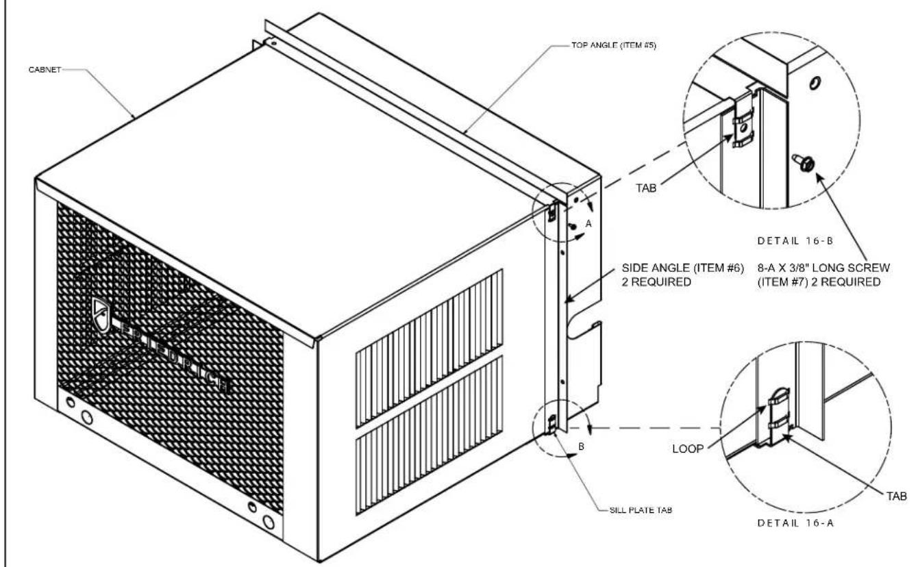
Shell (Cabinet) Preparation for Installation
STEP 1 Remove still plate and bend the taps up and reinstall 4" back from original shipping position. Move shell guides 4" forward (to the forward-most hole in the shell rail). See [DETAIL 16-A].
STEP 2 Take the side angles (item #6) and engage its loops in the tabs (both sides) of the sill plate. (DETAIL 16-A).
STEP 3 Take the top Flange (item #5) and engage its tabs in the top loops of the side flanges (DETAIL 16-B).
STEP 4 Install two (2) screws (Item #7) to secure the top angle tabs and the side angle in the side of the cabinet (Detail 16-B).
Figure 16
text_image
CABNET TOP ANGLE (ITEM #5) TAB DETAIL 16-B SIDE ANGLE (ITEM #6) 2 REQUIRED 8-A X 3/8" LONG SCREW (ITEM #7) 2 REQUIRED LOOP SILL PLATE TAB DETAIL 16-A TABShell Installation: Sash Window Installations
WARNING
Falling Object Hazard
Not following Installation Instructions for mounting your air conditioner can result in property damage, injury, or death.

STEP 1 Check the window sill and frame to be sure they are in good condition and firmly anchored to the wall. Repair if necessary.
STEP 2 CABINET MOUNTING: Raise the lower window sash 1/4" more than the height of the cabinet. Carefully slide the cabinet through the open window until the sill plate channel rests behind the window sill and the top support angle (Item #5) rests against the window (See Figure 17). Center the cabinet side to side and drill three (3) 5/32" diameter pilot holes into the window sill using the holes in the cabinet sill plate as a guide. Install three (3) #12A x 2" long screws (Item #4) (See Figure 17).
Figure 17
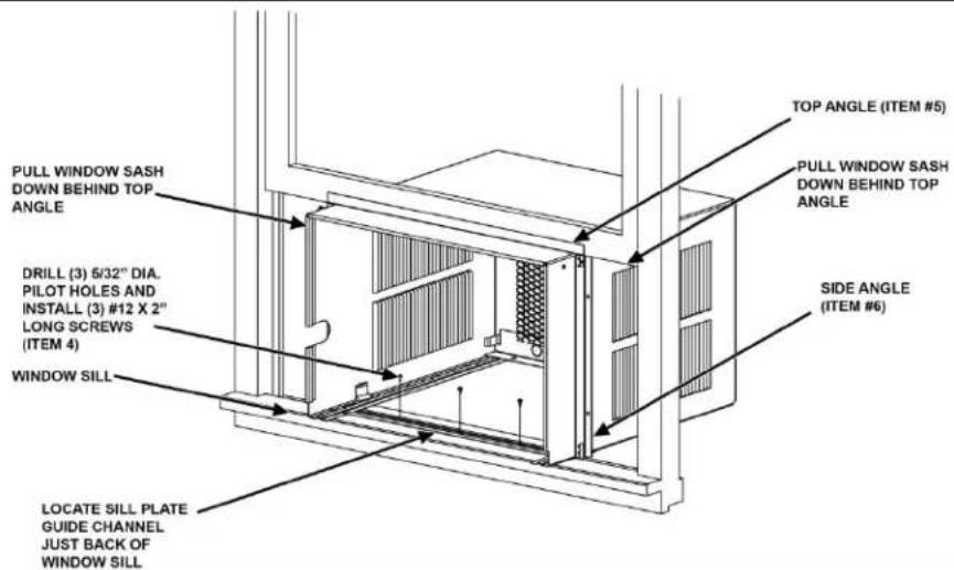
text_image
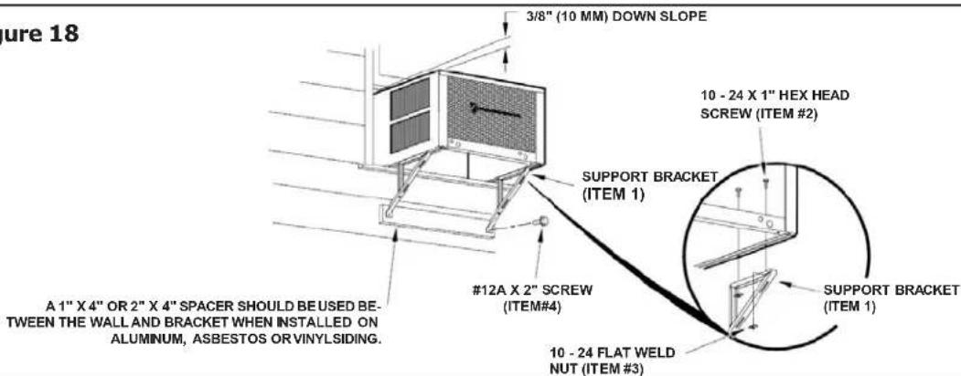
PULL WINDOW SASH DOWN BEHIND TOP ANGLE DRILL (3) 6/32" DIA. PILOT HOLES AND INSTALL (3) #12 X 2" LONG SCREWS (ITEM 4) WINDOW SILL LOCATE SILL PLATE GUIDE CHANNEL JUST BACK OF WINDOW SILL TOP ANGLE (ITEM #5) PULL WINDOW SASH DOWN BEHIND TOP ANGLE SIDE ANGLE (ITEM #6)STEP 3 OUTSIDE SUPPORT MOUNTING: Assemble the support brackets (Item #1) to the bottom rails of the cabinet with four (4) 10-24 1" long screws (Item #2) and four (4) 10-24 flat nuts (Item #3). Adjust the support brackets to bring the bottom pads in contact with the wall surface. (See Figure 18.)
A 1" x 4" or 2" x 4" SPACER SHOULD BE USED BETWEEN THE WALL AND THE SUPPORT BRACKETS WHEN INSTALLED ON ALUMINUM OR VINYL SIDING). Drill 5/32" (4 mm) diameter pilot holes, and secure the brackets to the wall with two (2) #12A x 2" long screws (Item #4). Adjust the support brackets to provide an approximate 3/8" (10 mm) down slope towards the outside for drainage. Tighten all screws. (See Figure 18).
Figure 18
text_image
Figure 18 3/8" (10 MM) DOWN SLOPE 10 - 24 X 1" HEX HEAD SCREW (ITEM #2) SUPPORT BRACKET (ITEM 1) #12A X 2" SCREW (ITEM#4) SUPPORT BRACKET (ITEM 1) 10 - 24 FLAT WELD NUT (ITEM #3) A 1" X 4" OR 2" X 4" SPACER SHOULD BE USED BE- TWEEN THE WALL AND BRACKET WHEN INSTALLED ON ALUMINUM, ASBESTOS OR VINYLSIDING.Typical Installation: Sill Plate
The illustrations below show a standard frame construction installation as well as some suggested ways of adapting the support bracket to thick walls and large brick ledges.
NOTICE
Instructions for mounting sleeve with slope must be observed to prevent entry of water into room.
Failure to follow instructions can result in property damage.
Figure 19
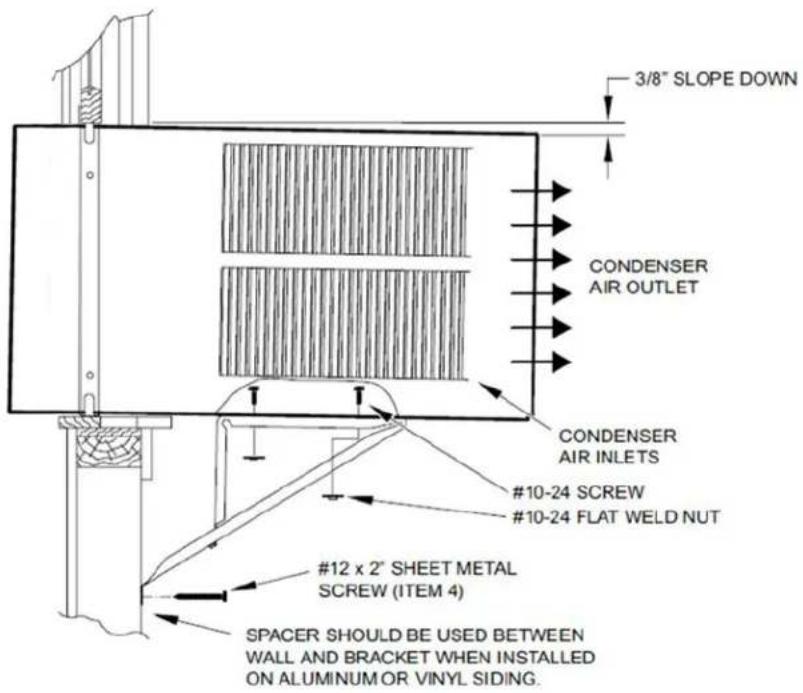
text_image
3/8" SLOPE DOWN CONDENSER AIR OUTLET CONDENSER AIR INLETS #10-24 SCREW #10-24 FLAT WELD NUT #12 x 2" SHEET METAL SCREW (ITEM 4) SPACER SHOULD BE USED BETWEEN WALL AND BRACKET WHEN INSTALLED ON ALUMINUM OR VINYL SIDING.Figure20
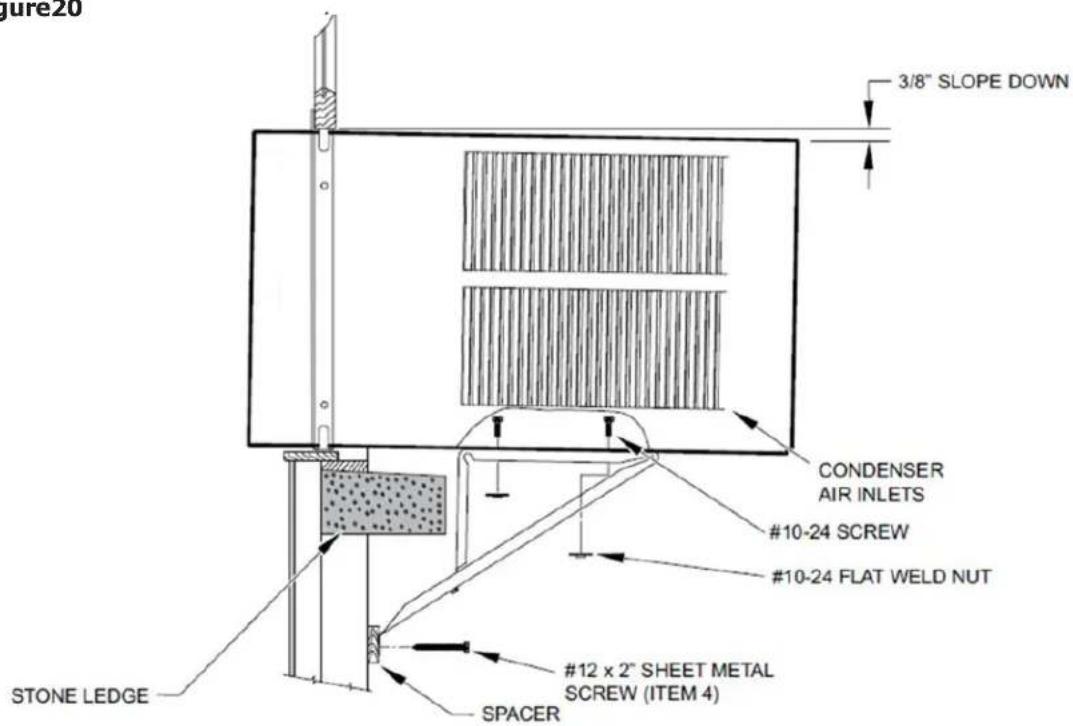
text_image
Figure20 3/8" SLOPE DOWN CONDENSER AIR INLETS #10-24 SCREW #10-24 FLAT WELD NUT #12 x 2" SHEET METAL SCREW (ITEM 4) SPACER STONE LEDGETypical Installation: Sill Plate (cont.)
Figure 21

text_image
3/8" SLOPE DOWN #10-24 SCREW STRAIGHTEN TAB TO LAY FLAT ALONG THE BOTTOM RAIL OF THE SHELL #10-24 FLAT WELD NUT SECURE THE LONGEST SIDE OF THE BRACKET TO THE SHELL ADJUST IN OR OUT TO REST ON THE LEDGE STONE LEDGEFigure 22
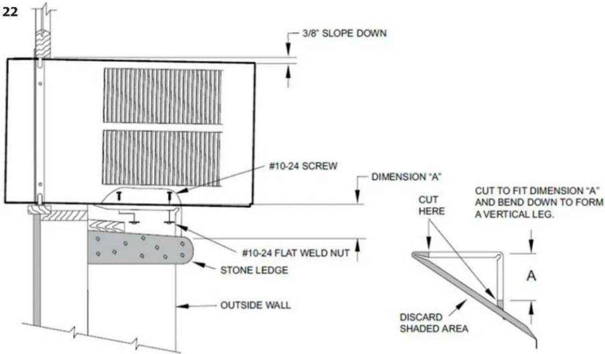
text_image
22 3/8" SLOPE DOWN #10-24 SCREW DIMENSION "A" #10-24 FLAT WELD NUT STONE LEDGE OUTSIDE WALL CUT TO FIT DIMENSION "A" AND BEND DOWN TO FORM A VERTICAL LEG. CUT HERE DISCARD SHADED AREAFigure 23
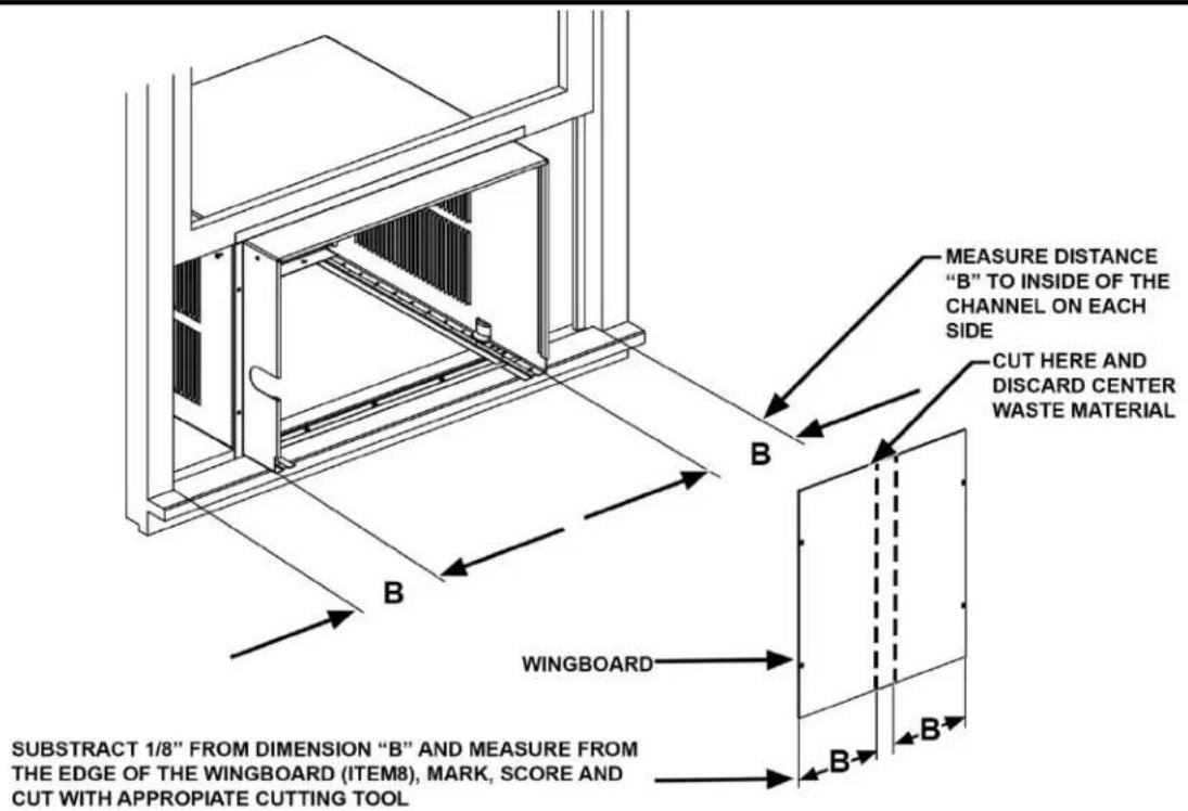
text_image
MEASURE DISTANCE "B" TO INSIDE OF THE CHANNEL ON EACH SIDE CUT HERE AND DISCARD CENTER WASTE MATERIAL B B WINGBOARD B SUBSTRACT 1/8" FROM DIMENSION "B" AND MEASURE FROM THE EDGE OF THE WINGBOARD (ITEM8), MARK, SCORE AND CUT WITH APPROPRIATE CUTTING TOOLSTEP 4 CUT WINGBOARD PANELS: Measure and cut the wingboard panels from the supplied masonite (Item #8) to fit the spaces between the side window channels and the sides of the cabinet (See Figure 23).
NOTE: AFTER CUTTING PANELS, MAKE A TRIAL TEST TO SEE IF THEY FIT THE SPACE WITH ABOUT 1/8" CLEARANCE BEFORE GOING TO STEP 5.
Figure 24
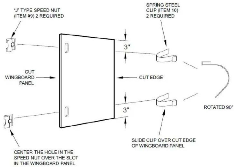
text_image
"J" TYPE SPEED NUT (ITEM #9) 2 REQUIRED SPRING STEEL CLIP (ITEM 10) 2 REQUIRED 3" CUT WINGBOARD PANEL 3" CUT EDGE 3" SLIDE CLIP OVER CUT EDGE OF WINGBOARD PANEL ROTATED 90° CENTER THE HOLE IN THE SPEED NUT OVER THE SLOT IN THE WINGBOARD PANELSTEP 5 ASSEMBLE CLIPS TO WINGBOARD PANELS: Assemble "J" type speed nuts (Item #9) and spring steel clips (Item #10) to the edges of the cut wingboard panels (See Figure 24).
Figure 25
SECTION A -A
TOP OF CABINET
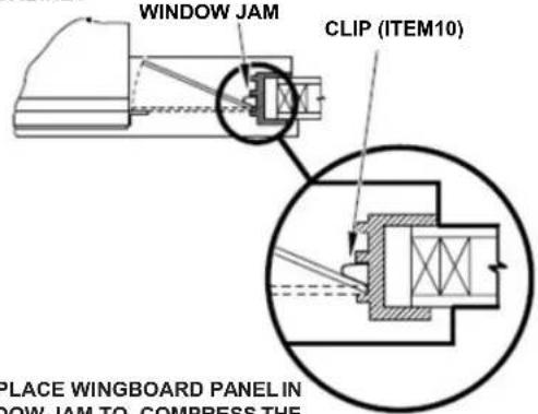
text_image
WINDOW JAM CLIP (ITEM10) PLACE WINGBOARD PANEL IN NOW JAM TO COMPRESS THEPLACE WINGBOARD PANEL IN WINDOW JAM TO COMPRESS THE SPRINGS INSIDE THERUNNERS, AND SWING THE PANEL INTO PLACE INDICATED BY THE DOTTED LINE.

natural_image
Technical line drawing of a mechanical or electrical enclosure with internal components and directional arrows (no text or symbols)SECURE THE SIDE WINGBOARD PANELS TO THE SIDE ANGLES WITH FOUR (4) #8 X 1/2" LONG SCREWS (ITEM #11), TWO ON EACH SIDE.
STEP 6 INSTALL SIDE WINGBOARD PANELS: Be sure that the cabinet has been secured to the window sill and the outside support brackets have been installed as shown in (Figures 19 and 20) on Page 17. Raise the window sash and install the right and left side wingboard panels (See Figure 25).
STEP 7 INSTALL WINDOW SEALING GASKETS: Measure and cut the dark foam window seal gasket (Item#12) and install it between the upper glass panel and the top part of the lower sash (Figure 26).
Figure 26
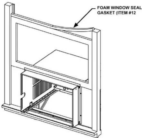
text_image
FOAM WINDOW SEAL GASKET (ITEM #12)NOTE FOR REASONS OF SECURITY, THE CUSTOMER MUST PROVIDE A MEANS OF PREVENTING THE WINDOW FROM OPENING.
STEP 8 When possible, caulk the outside of the installation with industrial type caulking to prevent air and water leaks.
STEP 9 Skip to chassis wiring and preparation on page 21 for Non ATEX or page 23 for ATEX and IECEx.
Chassis Wiring and Preparation (Non ATEX)
PROVIDED HARDWARE
1 JUNCTION BOX
2 MOUNTING LEGS
2 LEG SCREWS
2 HOLE COVERS
1 STAINLESS STEEL
GROUND SCREW
2 SCREWS
1 SHEET METAL SCREW
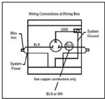
text_image
Wiring Connections at Wiring Box Wire Nut BRK GRN System Ground BLK System Power Use copper conductors only BLK or WHSTEP1 Remove the junction box, cover and screws from the shipping position underneath the fan motor (See Figure 7). Install one junction box mounting leg in the upper left position facing the rear of the junction box. (Figure 27)
Figure 27
natural_image
Line drawing of a hand inserting a plug into a device (no text or symbols)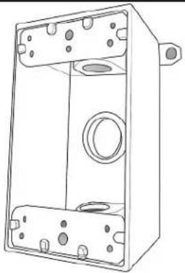
natural_image
Technical line drawing of a mechanical housing or enclosure with mounting holes and internal components (no text or symbols)STEP2 Remove and discard the threaded bushing wire protector from the conduit connector on the side panel of the control compartment. Install field supplied cable gland as required. Strip the wires approximately 1/2 inch (13 mm).
Figure 28
natural_image
Technical line drawing of a mechanical or electrical component with mounting brackets and internal components (no text or symbols)Chassis Wiring and Preparation
STEP 3 Insert all wires into the rear of the junction box and thread the box onto the threaded bushing until tight.
Figure 29
natural_image
Line drawing of hands using a tool to adjust or install a mechanical component (no text or symbols)STEP 4 Back off clockwise until the junction box is vertical with the mounting leg at the upper-right position facing the box opening. Be sure that the shell can slide between this box and the chassis.
Figure 30
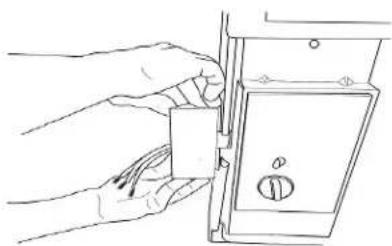
natural_image
Line drawing of a hand inserting a component into a door lock (no text or symbols)STEP 5 Insert the unit in the shell see Page 25 for help, be sure that the shell can slide between junction box and the chassis.
NOTE: Field wiring conductors to be copper and a minimum of 12 AWG. Complete junction box wiring and cover to prevent ingress from dust and moisture. All wiring connections to the junction box are to be made with cable glands.
Figure 31
natural_image
Line drawing of a modular air conditioning unit with ventilation grilles and control panel (no text or symbols)
natural_image
Line drawing of hands using a tool to adjust or install a component (no text or symbols present)Chassis Wiring and Preparation (ATEX & IECEx Models)
STEP1 Remove the junction box from the shipping position underneath the fan motor (Figure 7). Install junction box mounting legs to back of the junction box using 4 provided machine screws (Figure 32-1). Mount junction box to provide holes on side of air conditioner sleeve using 4 provided sheet metal screws and 4 serrated washers. Ensure serrated washers are between legs of junction box and painted metal sleeve (figure 32-2).
Figure 32
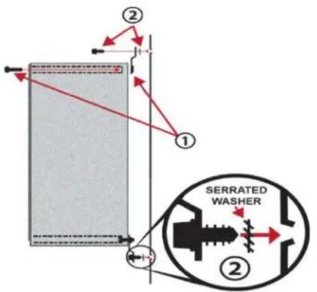
text_image
② ① SERRATED WASHER ②STEP 2 Proceed to make the STEP 1 of the Chassis Installation (see page 25) then come back to STEP 3
STEP 3 Insert air conditioner's electric cable through provided cable gland on bottom of electrical junction box and tighten cable gland nut (see Item 3) torque to 15 N-m, 106 in-lbs. Strip the three electrical conductors approximately 6.35 mm (1/4 inch) install under provided terminal block LINE terminals and tighten (Item 4). Fixed field wiring must include a field provided disconnect (all poles). Provide fixed field wiring conductors and cable gland with a minimum IP44 rating. Connect wiring conductors under provided terminal block LOAD terminals and tighten (Item 5). Field conductors to be copper and a minimum 1.29 to 2.06 mm (16 to 12 AWG). Ensure both LINE, LOAD and GROUNDS are adequately secured to provide termination points.
Figure 33
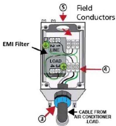
text_image
Field Conductors EMI Filter 1 2 LINE LOAD 3 4 ⑤ ④ ③ CABLE FROM AIR CONDITIONER LOAD.-FIELD CONNECTION-
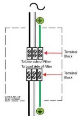
text_image
To Line side of Filter To Load side of Filter Terminal Block Terminal Block A/BOX, REC, Re ENL LONOR-AIR CONDITIONER-
NOTE: Terminal block screw tightening torque .56N-m (5 in lbs) max. Wire size should be 1.29 to 2.06 mm (12 to 16AWG)
NOTE: Notice: this air conditioner must be installed in accordance with national wiring regulations of country where installed. Electrical connections to equipment must be carried out by qualified personnel per EN/IEC 6079-14. Fixed wiring must include a field provided disconnect (all poles.) Repairs affecting hazard location protection must be carried out by a qualified electrician in accordance with NEC/CEC 501.10 (B) and EN/IEC 60079-19.
NOTE: To maintain IP44 protection and electrical safety, the Hazardgard unit must be installed in accordance to the installation instructions provided with this product.
Chassis Wiring and Preparation (ATEX & IECEx Models)
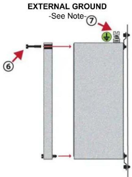
STEP 4 Complete junction box wiring, cover and tighten cover screws (Figure 34-6) to prevent ingress from dust and moisture. NOTE: Per EN/IEC 60079-0, external grounding or earthing may be necessary.
If required, use provided external ground clamp which can accept two cables of up to 6mm (Figure34-7).
Figure 34
text_image
EXTERNAL GROUND -See Note- ⑦ ⑥ ① HALLNOTE: This air conditioner shall be installed in accordance with national wiring regulations of the country where installed. Electrical connections to equipment must only be carried out by qualified personnel per NEC/CEC 501.10 (B) EN/IEC 60079-14. Repairs affecting hazard location protection must be carried out by a qualified electrician in accordance with NEC/CEC 501.10 (B) EN/IEC 60079-19.
Figure 35
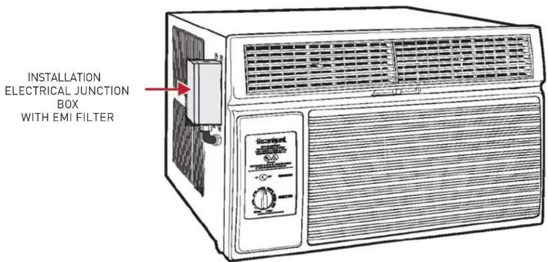
text_image
INSTALLATION ELECTRICAL JUNCTION BOX WITH EMI FILTERChassis Installation
STEP1 Slide the chassis into the cabinet stopping approximately 3" from full insertion. Stuff the chassis seal gasket (Item
12) one inch deep between the chassis and the cabinet (Figure 36). Begin at either bottom corner and go up the side, across the top, and down the opposite side. Make sure that the gasket is behind the conduit connector (furthest from you). Push the chassis into the shell the remaining distance so that the plastic front shrouds the front edge of the shell. Fasten the junction box mounting foot to the shell with the sheet metal screw.
If chassis seal gasket is not installed, the operation of the unit will be negatively affected. Also, the operation noise and outside noise will be amplified.
CAUTION
Excessive Weight Hazard
Usetwo or more people when installing your air conditioner.
Failure to do socan result in backor other injury.
CAUTION

Cut/Sever
Although great care has been taken to minimize sharp edges in the construction of your unit, use gloves or other hand protection when handling unit. Failure to do socan result in minor to moderate personal injury.
WARNING

Explosion Hazard

Electrical Shock Hazard
Electrically connect unit in accordance with NEC Code Article 501. Failure to do so can result in death, explosion, fire, or electrical shock.
NOTE: Field wiring must be provided to this junction box in accordance with NATIONAL ELECTRIC CODE (NFPA 70, 2008 or current edition) ARTICLE 501. Field and equipment grounds are to be terminated at the post in the junction box with the green screw provided. Equipment power leads are to be connected with the field supply by means of wire nuts (not provided). Install the gasket and cover plate onto the junction box.
Figure 36
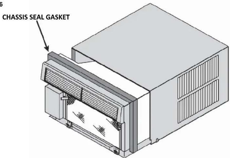
text_image
CHASSIS SEAL GASKETSTEP 2 Be sure that the filter is in place then install the return air grille (Figure 37). The top of the return air grille can be butted against the bottom of the discharge plenum. Snap the grille into place by pushing the grille up and onto the unit's latches at the bottom. (See Detail 37-4).
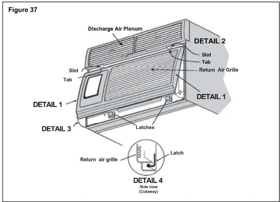
text_image
Figure 37 Discharge Air Plenum Slot Tab RETURN AIR GRILLE DETAIL 2 Slot Tab DETAIL 1 DETAIL 1 DETAIL 3 Latches RETURN AIR GRILLE Latch DETAIL 4 Side view (Cutaway)STEP 3 You have completed your installation. Conduct a review of your installation to insure that the unit is safely and securely installed.
End of Life
Customers are advised to ensure that the unit is disposed of in accordance with federal, state and local guidelines of their country. Contact your municipal department of public works to inquire about the procedures for collecting and disposing of refrigerated appliances / air conditioners in your neighborhood.
Maintenance Checklist
Won't Cool
If the unit operates, but doesn't cool, check to see that the controls are properly set. Inspect the filter and if needed, clean it thoroughly. Check to see if the chassis seal gasket is installed (refer to installation instructions).
Won't Run
If the unit does not operate at all, check that the power supply connections are present and tight. Check for blown fuses or tripped circuit breakers. Replace blown fuses with the proper size time-delay fuse. The nameplate on the unit shows the proper fuse size. After restoring power, wait three minutes before restarting the unit.
Inside Coil Freezes Up
Your Friedrich Hazardgard is designed not to freeze with outdoor temperatures as low as 45^ F ( 7^ C). Freezing should only occur when the outside air is damp and below 45^ F ( 7^ C). If the indoor coil should ice over while cooling, set the thermostat to the warmest position until the ice is gone. Setting the thermostat to a slightly warmer position will probably keep ice from forming on the coil. A dirty filter will contribute to coil icing.
Cleaning
The front grille of your Friedrich, as well as the complete cabinet may be cleaned with warm water and a mild detergent. The coils and base pan should be cleaned periodically for the most efficient operation. We suggest you call your Friedrich dealer for this service.
Lubrication
Fan motors are factory lubricated and sealed. No lubrication is required.

FRIEDRICH
Friedrich Air Conditioning Company
10001 Reunion Place, Suite 500
San Antonio, TX 78216
800.541.6645
www.friedrich.com
HAZARDGARD®
ROOM AIR CONDITIONERS
LIMITED WARRANTY
LIMITED ONE YEAR PARTS WARRANTY
- Limited warranty – One year. Friedrich warrants that it will provide a replacement for any part of this HazardGard Room Air Conditioner found defective in material or workmanship for a period of one (1) year from the date of original purchase.
- Limited warranty – One year. The Friedrich warranty also covers the cost of labor for repairing any compressor, condenser, evaporator or inter-connecting tubing found defective within the warranty period, providing the unit is returned to an authorized Friedrich Repair Station located within the Continental United States.
The Friedrich warranty does not cover:
(1) Any charges for removal, transportation or reinstallation of the unit; (2) the cost of labor to replace parts other than those described above; and (3) does not apply to any HazardGard Room Air Conditioner that has been subject to (a) accident, misuse, flood, fire, or neglect; (b) repairs or alterations outside of the Friedrich Authorized Dealer or Service Center so as to affect adversely its performance and reliability; or (c) any repairs or servicing as a result of using parts not sold or approved by Friedrich.
LIMITATIONS: This warranty is a LIMITED warranty. Anything in the warranty notwithstanding, IMPLIED WARRANTIES FOR PARTICULAR PURPOSE AND MERCHANTABILITY SHALL BE LIMITED TO THE DURATION OF THE EXPRESS WARRANTY. MANUFACTURER EXPRESSLY DISCLAIMS AND EXCLUDES ANY LIABILITY FOR CONSEQUENTIAL OR INCIDENTAL DAMAGES FOR BREACH OF ANY EXPRESSED OR IMPLIED WARRANTY.
Performance of Friedrich's Warranty obligation is limited to one of the following methods:
- Repair of the unit
- A refund to the customer for the prorated value of the unit based upon the remaining warranty period of the unit.
- Providing a replacement unit of equal value
The method of fulfillment of the warranty obligation is at the sole discretion of Friedrich Air Conditioning.
(11-10)

FRIEDRICH
Friedrich Air Conditioning Company
10001 Reunion Place, Suite 500
San Antonio, TX 78216
800.541.6645
www.friedrich.com
INTERNATIONAL LIMITED WARRANTY
TERMS OF LIMITED WARRANTY
Friedrich Air Conditioning Co. warrants to the original purchaser that this Friedrich Air Conditioner is free from defects as to material and workmanship.
This Warranty pertains to such manufacturing defects as may develop through normal usage and is in effect for a period of 12 months from date of installation or 18 months from the original date of purchase (date of invoice), whichever date shall occur first. The Company's obligation under this Warranty is limited to furnishing (FOB San Antonio, Texas – no freight allowed), at its option, either a suitable replacement part or a remanufactured part or assembly for the sole purpose of replacing any part or parts which may be defective. All such warranty claims shall be directed through an authorized Friedrich Distributor/Dealer. Friedrich reserves the right to have the defective part returned to Friedrich for examination at the customer's expense.
This Warranty does not apply to air filters, fuses, cabinet enclosures, refrigerant charge, and damage to any part resulting from installation not in accordance with manufacturer's recommendations; nor does it apply to exterior finishes, except where examination discloses that same was defective at the time of initial shipment. This Warranty also does not apply to a Friedrich Air Conditioner, or any part thereof, which has been subject to misuse, neglect, alteration, accident, flood, fire, or Act of God. No warranty shall apply if the product has been used on electrical circuits of voltage and cycle characteristics other than specified on the model and serial number plate.
GENERAL TERMS
The furnishing of replacement parts as described above shall constitute complete fulfillment of all obligations with respect to the Friedrich Air Conditioner. Under no circumstances does Friedrich assume any responsibility for service, labor costs, or transportation charges. THESE WARRANTIES ARE GIVEN IN LIEU OF ALL OTHER WARRANTIES, EXPRESS OR IMPLIED, INCLUDING THE IMPLIED WARRANTIES OF MERCHANTABILITY OR FITNESS FOR A PARTICULAR PURPOSE.

FRIEDRICH
Friedrich Air Conditioning LLC
10001 Reunion Place, Suite 500
San Antonio, Texas 78216
800.541.6645
www.friedrich.com
Printed in Mexico 93031008_02

FRIEDRICH
Hazardgard®
natural_image
Line drawing of a portable air conditioner unit with ventilation grilles and control panel (no text or symbols)(National Electric Code)
Artículo 501 ATEX*
Underwriters Laboratories....6
text_image
Hazardgard® ROOM AIR CONDITIONER For use in Hazardous Locations Class I, Division 2, GROUPS A, B, C, D Operating Temperature Code: T4 C US LISTED 933X This equipment must be installed per National Electric Code (NFPA 70) Article 501 Ex ec nA nC IIC T4 Gc IECEx UL15.0051X 8°C ≤ Tamb ≤55°C ATEX CE ON II 3 G Ex ec nA nC IIC T4 Gc DEMKO 15 ATEX 1364X OFF ON POWER MIN TEMP MAX COOL Allow 3 min. between restartsnatural_image
Simple line drawing of a box with scissors and a cup, no text or symbols present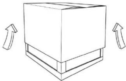
natural_image
Simple line drawing of a cardboard box with two upward arrows indicating direction (no text or symbols)text_image
Diagram showing a computer monitor with hands operating it, labeled with arrows and numbered parts indicating process flow.natural_image
Line drawing of a mechanical enclosure with a hand inserting a screwdriver into it (no text or symbols)natural_image
Line drawing of hands operating a microwave oven with a door panel (no text or symbols)natural_image
Technical line drawing of a mechanical assembly with arrows indicating components (no text or symbols)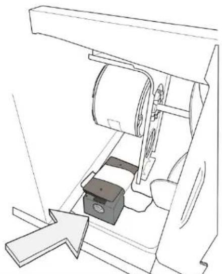
natural_image
Technical line drawing of a mechanical assembly with no visible text or symbolsnatural_image
3D diagram of a two-tiered structural frame with labeled dimensions A and B (no text or symbols beyond labels)natural_image
Technical line drawing of a mechanical assembly with no visible text or symbolsnatural_image
Line drawing of a hand using a tool to press or install a component on a base (no text or symbols)
natural_image
Technical line drawing of a mechanical housing or enclosure with mounting holes and internal components (no text or symbols)natural_image
Technical line drawing of a mechanical or electrical component with no visible text or symbolsnatural_image
Line drawing of hands using a tool to adjust or install a mechanical component (no text or symbols)natural_image
Line drawing of a hand inserting a component into a door lock (no text or symbols)natural_image
Line drawing of a modular air conditioning unit with ventilation grilles and control panel (no text or symbols)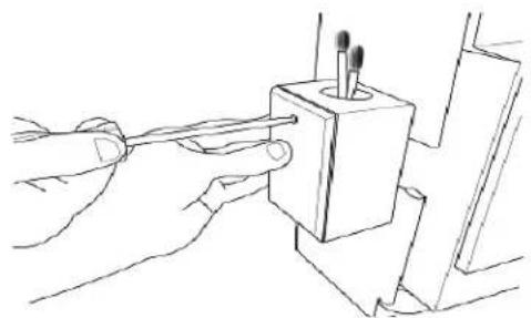
natural_image
Line drawing of hands using a tool to adjust or install a component with three pins (no text or symbols present)Friedrich Air Conditioning Company
10001 Reunion Place, Suite 500
San Antonio, TX 78216
800.541.6645
www.friedrich.com
HAZARDGARD®
Friedrich Air Conditioning Coog want to sale the prepaid purchase price this Ricianed and Certified herein restated before to material a material y mano de obra.
Friedrich Air Conditioning LLC
10001 Reunion Place, Suite 500
San Antonio, Texas 78216
800.541.6645
www.friedrich.com
Impreso en México
93031008_02

FRIEDRICH
Hazardgard®
natural_image
Line drawing of a portable air conditioner unit with ventilation grilles and control panel (no text or symbols)Underwriters Laboratories....6
Refrigeration of triglycerides in the right posterior.
text_image
Hazardgard® ROOM AIR CONDITIONER For use in Hazardous Locations Class I, Division 2, GROUPS A, B, C, D Operating Temperature Code: T4 C US LISTED 933X This equipment must be installed per National Electric Code (NFPA 70) Article 501 Ex ec nA nC IIC T4 Gc IECEx UL15.0051X 8°C ≤ Tamb ≤55°C ATEX CE II 3 G Ex ec nA nC IIC T4 Gc DEMKO 15 ATEX 1364X OFF ON POWER MIN TEMP MAX COOL Allow 3 min. between restartsnatural_image
Simple line drawing of a box with scissors and a recycling cup, no text or symbols present
natural_image
Simple line drawing of a cardboard box with two upward arrows indicating direction (no text or symbols)text_image
Diagram showing a computer monitor with airflow direction arrows and labeled parts, likely illustrating a process or system.natural_image
Line drawing of a mechanical enclosure with a hand inserting a screwdriver into its base (no text or symbols)natural_image
Line drawing of hands operating a microwave oven with a door panel (no text or symbols)natural_image
Technical line drawing of a mechanical assembly with arrows indicating components (no text or symbols)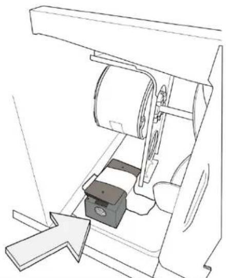
natural_image
Technical line drawing of a mechanical assembly with no visible text or symbolsnatural_image
3D diagram of a two-tiered structural frame with labeled dimensions A and B (no text or symbols beyond labels)EXIGENCES DE LA TAILLE DU TROU
| DIMENSION FINIE | CHÂSSISSH15 | CHÂSSISSH20, SH24 |
| A 41 cm | 46,2 cm | |
| B 66,5 cm | 66,5 cm |
REMARQUE : CES DIMENSIONS CONCERNENT LA TAILLE DU TROU FINI
Figure 12 CONSTRUCTION DE L'OSSATURE DU MUR CONSTRUCTION DU BLACAGE EN BRIQUE
text_image
CAMULTREZ TOUS LES CÔTÉS DE FAÇON ÉTANCHE ART-POUR REMOUIAT LE VIDE EN HAUT ET SUR LES CÔTÉS AVEC DU BOIS TEL QUE REQUIS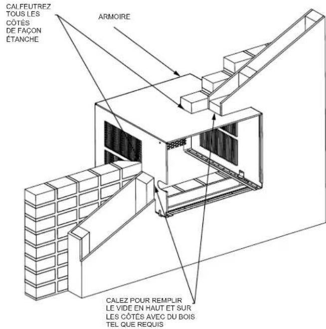
text_image
CALFEUTREZ TOUS LES CÔTÉS DE FAÇON ÉTANCHE ARMOIRE CALEZ POUR REMPLIR LE VIDE EN HAUT ET SUR LES CÔTES AVEC DU BOIS TEL QUE REQUISFigure 14
CONSTRUCTION SOLIDE EN MAÇONNERIE
text_image
CALFEUTREZ TOUS LES CÔTÉS DE FAÇON ÉTANCHE ACRAONEE MORTIER CONSTRUCTION SOLIDE Enatural_image
Line drawing of a hand inserting a small component into a rectangular device (no text or symbols)
natural_image
Technical line drawing of a mechanical housing or enclosure with mounting holes and internal components (no text or symbols)natural_image
Technical line drawing of a mechanical or electrical component with no visible text or symbolsnatural_image
Line drawing of hands using pliers to cut or adjust a mechanical component (no text or symbols)natural_image
Line drawing of hands installing or adjusting a door panel (no text or symbols)natural_image
Isometric line drawing of a modular air conditioning unit with ventilation grilles and control panel (no text or symbols)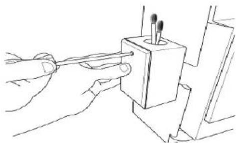
natural_image
Line drawing of hands using a tool to apply or install a component (no text or symbols present)Friedrich Air Conditioning Company
Friedrich Air Conditioning LLC
10001 Reunion Place, Suite 500