
MDRDS6000 - Earphones SONY - Free user manual and instructions
Find the device manual for free MDRDS6000 SONY in PDF.
| Product Type | Digital Surround Sound Wireless Stereo Headphones (Headphone + Processor System) |
| Brand | Sony |
| Model | MDR-DS6000 (Headphones MDR-RF6000, Processor DP-RF6000) |
| Processor Dimensions | Approx. 182 × 38 × 182 mm (w/h/d) |
| Processor Weight | Approx. 345 g |
| Headphone Weight | Approx. 360 g (with rechargeable battery) |
| Processor Power Supply | 9 V DC power adapter (supplied) |
| Headphone Power Supply | Rechargeable nickel-metal hydride battery (supplied) or AA alkaline batteries (not supplied) |
| Rechargeable Battery Life | Approx. 7 hours (full charge in 3 hours) |
| Carrier Wave Frequency | 2.412 – 2.462 GHz (2.4 GHz ISM band) |
| Transmission Range | Approx. 30 meters maximum |
| Frequency Response | 12 – 22,000 Hz (digital input, 48 kHz sampling frequency) |
| Distortion Rate | 1% or less (at 1 kHz) |
| Audio Inputs | 1 × optical digital input (rectangular type), 1 × analog input (RCA L/R jacks) |
| Audio Output | 1 × optical digital output (rectangular type, pass-through) |
| Supported Audio Formats | Dolby Digital, Dolby Pro Logic II, DTS, MPEG-2 AAC |
| Sound Effect Modes | CINEMA, MUSIC, OFF (Virtualphones Technology) |
| Dynamic Compression Function | Yes (COMPRESSION ON/OFF switch) |
| Automatic Functions | Automatic power on/off by detecting headphone wearing, automatic recharging on cradle, automatic processor shutdown after 5 minutes without audio signal |
| Headband | Self-adjusting (no manual adjustment) |
| Earpads | Removable and replaceable (reference not supplied) |
| Transducers | Long-stroke XD diaphragms, 40 mm wide |
| Included Accessories | Power adapter, optical digital cable (1.5 m), Ni-MH rechargeable battery, user manual |
| Repairability | Only to be serviced by qualified technician. Spare parts available from authorized Sony dealers (earpads, rechargeable battery BP-HP2000) |
| Maintenance and Cleaning | Soft cloth lightly moistened with a mild detergent solution. Do not use solvents. |
Frequently Asked Questions - MDRDS6000 SONY
User questions about MDRDS6000 SONY
0 question about this device. Answer the ones you know or ask your own.
Ask a new question about this device
Download the instructions for your Earphones in PDF format for free! Find your manual MDRDS6000 - SONY and take your electronic device back in hand. On this page are published all the documents necessary for the use of your device. MDRDS6000 by SONY.
USER MANUAL MDRDS6000 SONY
Digital Surround Headphone System
Operating Instructions US
Mode d'emploi FR
To reduce the risk of fire or electric shock, do not expose this apparatus to rain or moisture.
To avoid electrical shock, do not open the cabinet. Refer servicing to qualified personnel only.
For the customers in the USA
Owner's Record
The model number is located at the bottom of the processor and the left inner side of the headband.
The serial number is located at the bottom of the processor and the inner side of the battery compartment.
Record these numbers in the spaces provided below. Refer to them whenever you call upon your Sony dealer regarding this product.
Model No. MDR-DS6000
Processor DP-RF6000
Headphones MDR-RF6000
Serial No.
Processor
Headphones ____
NOTE
The transmitter (Processor) must not be co-located or operated in conjunction with any other antenna or transmitter.
The transmitter (Processor) complies with FCC radiation exposure limits set forth for uncontrolled equipment and meets the FCC radio frequency (RF) Exposure Guidelines in Supplement C to OET65.
The transmitter (Processor) should be installed and operated with at least 20 cm and more between the radiator and person's body (excluding extremities: hands, wrists, feet and legs).
NOTICE FOR THE CUSTOMERS IN THE U.S.A.
NOTE
This equipment has been tested and found to comply with the limits for a Class B digital device, pursuant to Part 15 of the FCC Rules. These limits are designed to provide reasonable protection against harmful interference in a residential installation. This equipment generates, uses and can radiate radio frequency energy and, if not installed and used in accordance with the instructions, may cause harmful interference to radio communications. However, there is no guarantee that interference will not occur in a particular installation. If this equipment does cause harmful interference to radio or television reception, which can be determined by turning the equipment off and on, the user is encouraged to try to correct the interference by one or more of the following measures:
– Reorient or relocate the receiving antenna.
– Increase the separation between the equipment and receiver.
- Connect the equipment into an outlet on a circuit different from that to which the receiver is connected.
- Consult the dealer or an experienced radio/TV technician for help.
You are cautioned that any changes or modifications not expressly approved in this manual could void your authority to operate this equipment.
For the customers in the Canada
Operation is subject to the following two conditions: (1) this device may not cause interference, and (2) this device must accept any interference, including interference that may cause undesired operation of the device.
The transmitter (Processor) complies with IC radiation exposure limits set forth for uncontrolled equipment and meets RSS-102 of the IC radio frequency (RF) Exposure rules. The transmitter (Processor) should be installed and operated with at least 20 cm and more between the radiator and person's body (excluding extremities: hands, wrists, feet and legs).
RECYCLING NICKEL METAL HYDRIDE BATTERIES
Nickel Metal Hydride batteries are recyclable. You can help preserve our environment by returning your used rechargeable batteries to the collection and recycling location nearest you.

For more information regarding recycling of rechargeable batteries, call toll free 1-800-822-8837, or visit http://www.rbrc.org/
Caution: Do not handle damaged or leaking Nickel Metal Hydride batteries.
Table Of Contents
Main Features 4
Checking the Components and Accessories 6
Location and Function of Parts .. 7
Front Panel of the Processor .... 7
Rear Panel of the Processor .... 8
Headphone Part Descriptions ..... 9
Charging the Supplied Rechargeable Nickel-metal Hydride Battery 10
Inserting the supplied rechargeable nickel-metal hydride battery ..... 10
Charging.... 11
Checking the battery power ...... 13
Using the headphones with alkaline batteries (sold separately) ..... 14
Connecting the Headphone System 15
Connecting the processor to digital components .... 15
Connecting the processor to analog components 16
Listening to a Connected Component .... 18
Using Additional Headphones ... 23
Replacing the Ear Pads ...... 24
Troubleshooting 25
Precautions.... 29
Specifications 30
Main Features
The MDR-DS6000 is a digital surround headphone system using 2.4 GHz wireless digital transmission *1 . You can enjoy multi-channel surround sound with headphones by simply connecting the digital surround processor to a DVD device or a digital satellite/TV receiver, etc., with the supplied optical digital connecting cable.
- Compatibility of MDR-DS6000 with a wide variety of audio formats. Compatible with Dolby Digital 2 , Dolby Pro Logic II 2 , DTS 2 and MPEG-2 AAC 2 formats. (Can play media marked with “Dolby Digital Surround EX” and “DTS-ES”).
- W ireless headphones using a digital radio frequency transmission system which reproduces uncompressed transmission sound, resistant to external noise and interference.
- Wireless transmission means you can use these headphones anywhere indoors without worrying about things getting in the way. (Range: Up to approx. 30 m) *3
- Superior “Virtualphones Technology”*4 creates a surround sound field within the headphones with realistic presence.
- Built-in audio compression function for easy listening even in the bursting and whispering sound by compressing the dynamic range.
- Built-in digital through terminal. Signal to the DIGITAL IN terminal is parallel routed through, for convenient integration into your existing system with no need to reconfigure your hookup.
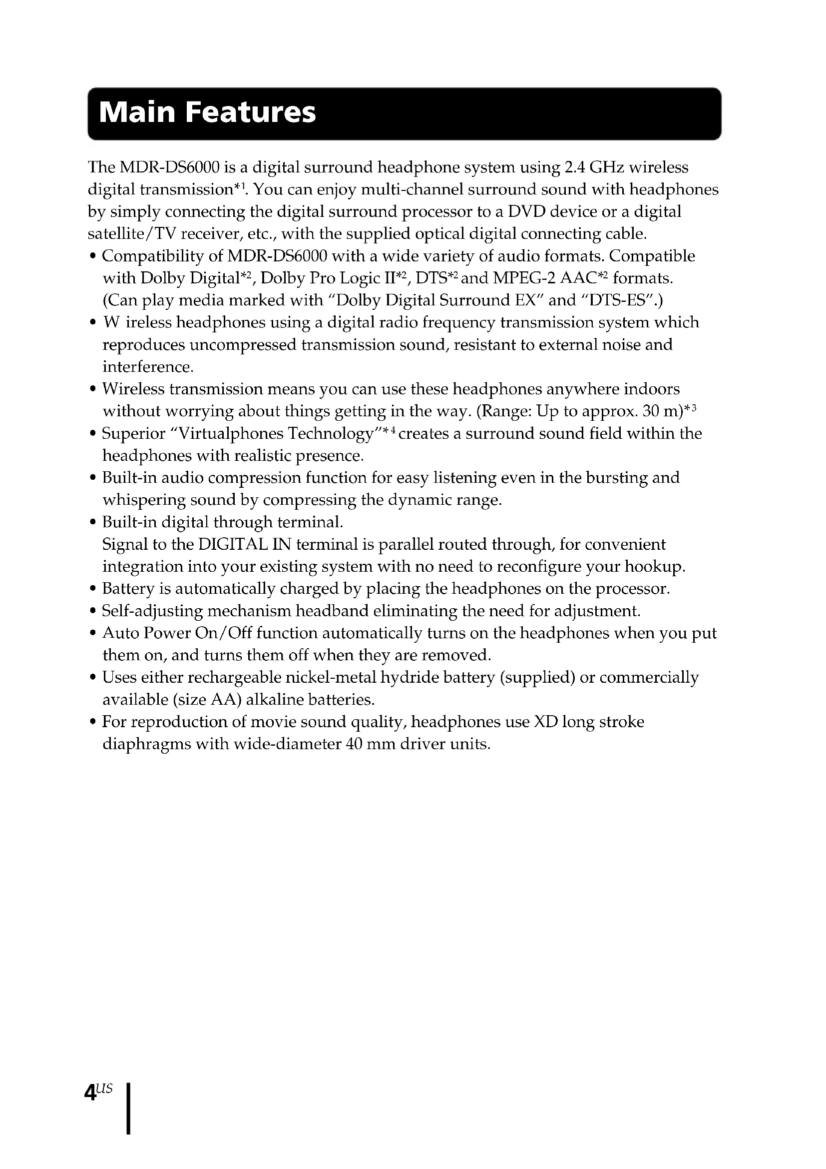
- Battery is automatically charged by placing the headphones on the processor.
- Self-adjusting mechanism headband eliminating the need for adjustment.
- Auto Power On/Off function automatically turns on the headphones when you put them on, and turns them off when they are removed.
- Uses either rechargeable nickel-metal hydride battery (supplied) or commercially available (size AA) alkaline batteries.
- For reproduction of movie sound quality, headphones use XD long stroke diaphragms with wide-diameter 40 mm driver units.
*1 "SYNIC Intelligent Wireless" is a trademark of Syncomm Technology Corp. to represent uncompressed digital radio frequency transmission technology. This technology employs a radio frequency carrier, by which audio signals are transmitted with minimum delay and high fidelity.
The digital surround processor for this system incorporates the Dolby Digital decoder, the Dolby Pro Logic II decoder, the DTS decoder and the MPEG-2 AAC decoder.
*2 Manufactured under licence from Dolby Laboratories and Digital Theater Systems, Inc.
"Dolby," "Pro Logic," the "AAC" logo, and the double-D symbol are trademarks of Dolby Laboratories.
“DTS” and “DTS Virtual” are trademarks of Digital Theater Systems, Inc.
AAC patent marking
Pat. 5,848,391; 5,291,557; 5,451,954; 5 400 433; 5,222,189; 5,357,594; 5 752 225; 5,394,473; 5,583,962; 5,274,740; 5,633,981; 5 297 236; 4,914,701; 5,235,671; 07/640,550; 5,579,430; 08/678,666; 98/03037; 97/02875; 97/02874; 98/03036; 5,227,788; 5,285,498; 5,481,614; 5,592,584; 5,781,888; 08/039,478; 08/211,547; 5,703,999; 08/557,046; 08/894,844
*3 Transmission distance varies depending on conditions of use.
*4 "Virtualphones Technology" is a registered trademark of Sony Corporation.
Checking the Components and Accessories
Before setting up the system, check that all of the components are included.
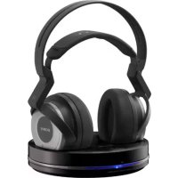
Wireless stereo headphones MDR-RF6000 (1)Processor DP-RF60
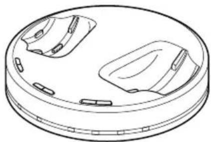
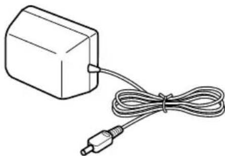
AC power adaptor (1)

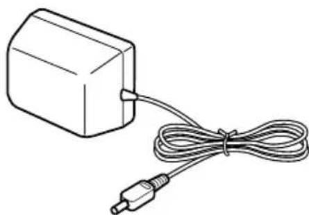
Rechargeable nickel-metal hydride battery BP-HP2000 (1)
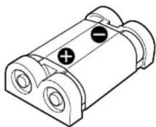
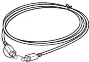
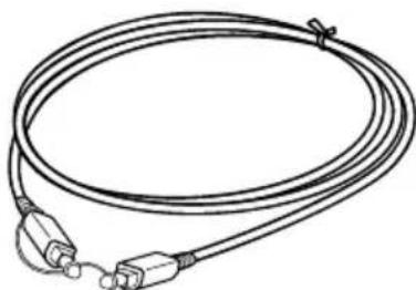
Optical digital connecting cable (rectangular type ↔ rectangular type) (1)
Location and Function of Parts
Front Panel of the Processor
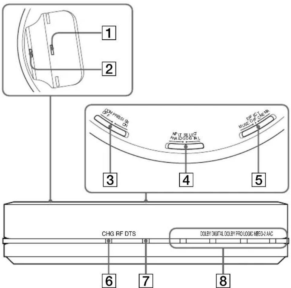
1 Contact pin
2 Charging lever
3 COMPRESSION switch
(See page 20 for details.)
4 INPUT SELECT switch
Slide to select the input source (DIGITAL/ANALOG).
5 EFFECT switch
(See page 19 for details.)
Slide to select the sound field (MUSIC/OFF/CINEMA).
6 CHG indicator
Lights red while charging.
7 RF indicator
Lights blue while emitting RF signals.
8 DECODE MODE indicators
(See page 20 for details.)
Rear Panel of the Processor
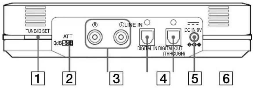
1 TUNE/ID SET button
(See pages 21 and 23 for details.)
Use this button when reception deteriorates, or when using additional headphones.
2ATT (attenuator) switch
Set this switch to "0 dB" if the volume is too low for analog input. Normally, this switch should be set to "-8 dB."
3 LINE IN jacks
(See page 16 for details.)
Connect the audio output jacks on an audio or video component (sold separately), such as a video cassette player or TV, to these jacks.
4 DIGITAL IN jack
(See page 15 for details.)
Connect a DVD device, digital satellite/TV receiver, or other digital component (sold separately) to this jack.
5 DIGITAL OUT jack
(See page 15 for details.)
Connected components' digital signal integrity retained when installed.
6 DC IN 9V jack
Connect the supplied AC power adaptor to this jack. (Be sure to use the supplied AC power adaptor. Using products with a different plug polarity or other characteristics can cause a malfunction.)
Headphone Part Descriptions
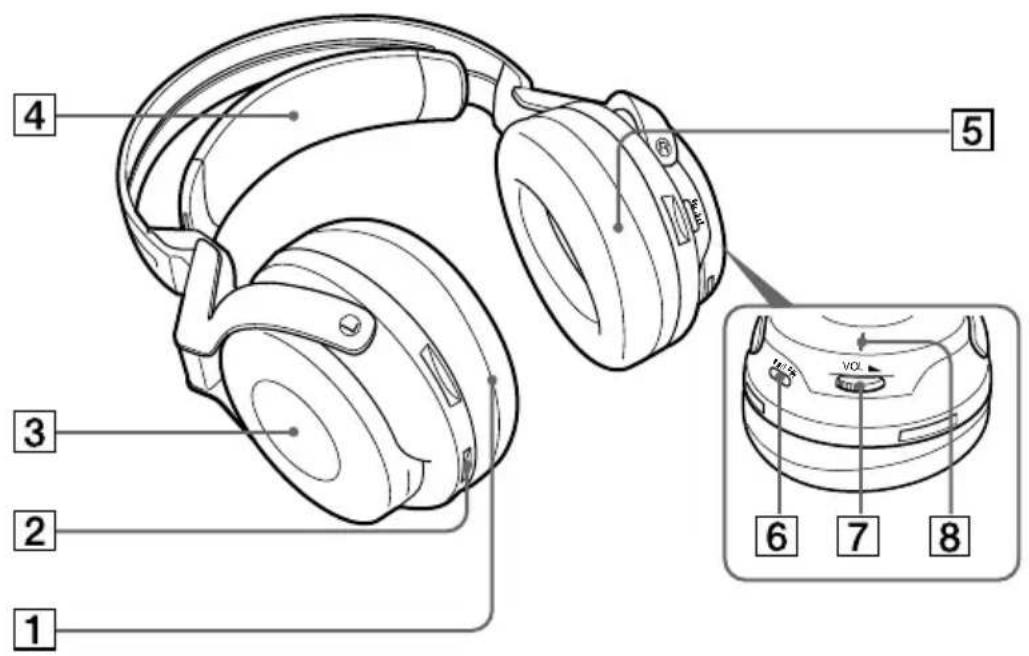
1 Ear pad (left)
2 Contact point
3 Battery case
This battery case is for the rechargeable nickel-metal hydride battery (supplied) or commercially available (size AA) alkaline batteries only.
4 Self-adjusting band
The headphones automatically turn on when you put them on.
5 Ear pad (right)
6 TUNE/ID SET button
(See pages 21 and 23 for details.)
Use this button when reception deteriorates, or when using additional headphones.
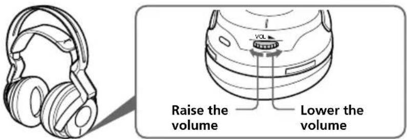
7 VOL (Volume) control
Use to adjust the volume.
8 POWER indicator
By pulling up the self-adjusting band, the indicator lights blue when battery power remains.
Charging the Supplied Rechargeable Nickel-metal Hydride Battery
The supplied rechargeable nickel-metal hydride battery is not charged from the first time you use it. Be sure to charge it before use.
To charge the headphones, place them on the processor.
Inserting the supplied rechargeable nickel-metal hydride battery
1 Open the battery compartment lid of the left housing.
The battery compartment lid comes off.
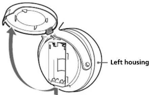
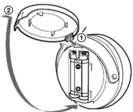
2 Insert the supplied rechargeable nickel-metal hydride battery into the battery compartment, matching the ⊕ terminal on the battery to the ⊕ mark in the compartment.
Do not attempt to charge any other kind of battery with this unit.

Note
The battery compartment has a tab on the side which holds the battery in place. Insert the terminal first when installing the battery.
3 Close the battery compartment lid.
Charging
1 If your AC power adaptor is equipped with an on/off switch, set it to ON. The power is supplied to the processor.
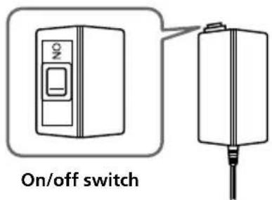
2 Connect the supplied AC power adaptor to the processor.
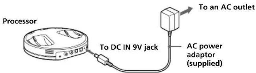
Notes
- Be sure to use the supplied AC power adaptor. Using AC adaptors with different plug polarity or other characteristics can cause product failure.

Unified polarity plug
- Be sure to always use the supplied AC power adaptor. Even AC power adaptors having the same voltage and plug polarity can damage this product due to the current capacity or other factors.
(Continued)
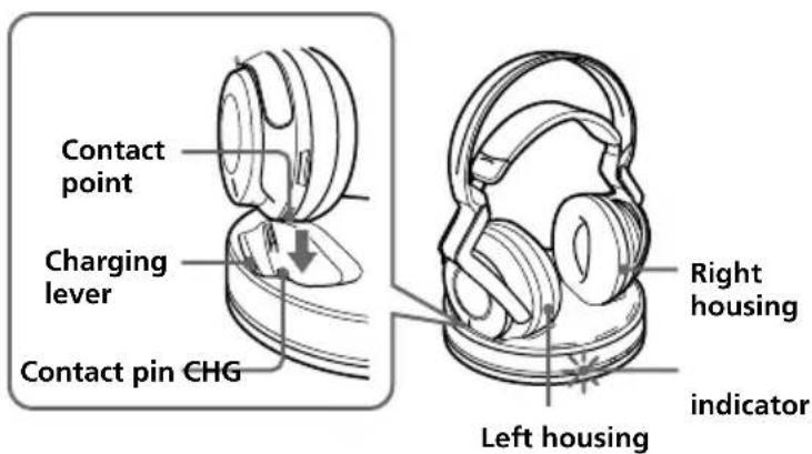
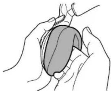
3 Rest the headphones on the processor so that the headphones' contact point meets the processor's contact pin, and make sure that the CHG indicator lights up.
It takes approx. 3 hours to fully charge the battery (the CHG indicator goes off when charging is complete).
When placing the headphones on the processor, be sure to hold them with both hands so that the right and left housings are horizontal, and place the headphones vertically on the processor. The charging lever is pushed down and the contact pin comes up. When the processor's contact pin meets the headphones' contact point, the CHG indicator lights up.
If the CHG indicator is not lit
- Be sure to close the battery compartment lid. The battery charge function is not activated when the lid is not fully closed.
- Check if the right and left headphones are rested on the processor correctly.
- The indicator will not light up if the headphones' contact point does not meet the processor's contact pin. In this case, remove the headphones and place them on the processor again so that the indicator lights up.
- Make sure that the supplied rechargeable nickel-metal hydride battery is installed in the battery compartment. Dry batteries cannot be charged.
- If the rechargeable battery is damaged or the and of the battery do not match those in the battery compartment correctly, the CHG indicator blinks.
To recharge the headphone battery after use
Place the headphones on the processor after use. The CHG indicator lights up, and the RF indicator goes off, and then charging starts.
Since the built-in timer recognizes when charging is complete (approx. 3 hours), there is no need to remove the headphones from the processor after charging has completed.
Notes
- The processor automatically turns off while charging the battery.
- This system is designed to charge only the supplied rechargeable battery, type BP-HP2000, for safety. Note that other types of rechargeable batteries cannot be charged with this system.
- If dry batteries are installed, they cannot be charged.
- Do not attempt to use the supplied BP-HP2000 rechargeable battery with other components. It is for use with this system only.
- Charge in an environmental temperature of between 0°C and 40°C (between 32°F and 104°F ). Otherwise, the battery may not be fully charged.
- Do not touch the contact pin of the processor. If a contact pin becomes dirty, charging may not be possible.
- Charging may not be completed if the processor's contact pin and headphones' contact point are dusty. Wipe them with a cotton bud, etc.
Charging and usage time
| Approx. charging time Approx. usage time* | 1 | |
| 3 hours*2 | 7 hours*3 | |
*1 at 1 kHz, 1 mW + 1 mW output
*2 hours required to fully charge an empty battery
*3 Time may vary, depending on the temperature or conditions of use.
Checking the battery power
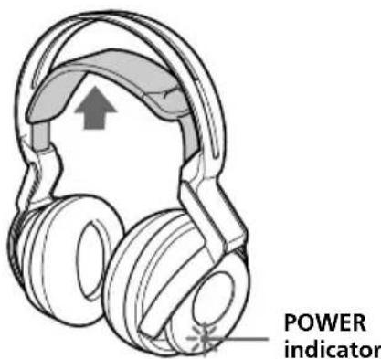
Pull up the self-adjusting band and check the POWER indicator located on the right housing. The battery is still usable when the indicator lights blue.
Charge the rechargeable battery or install new alkaline batteries if the POWER indicator does not light up.
Note
The rechargeable nickel-metal hydride battery should be replaced with a new one when it lasts only half the expected time, after a full charge has been performed. The rechargeable battery, type BP-HP2000, is not commercially available. You can order the battery from the store where you purchased this system, or at your nearest Sony dealer.
Using the headphones with alkaline batteries (sold separately)
Commercially available (size AA) alkaline batteries can also be used to power the headphones. Install the batteries in the same manner as described in “Inserting the supplied rechargeable nickel-metal hydride battery” (page 10).
When dry batteries are installed, the battery charge function is not activated.
Battery life
| Battery Approx. hours* | 1 |
| Sony alkaline batteries 5 hours* | 2 |
| LR6(SG) |
*1 at 1 kHz, 1 mW + 1 mW output
*2 Time may vary, depending on the temperature or conditions of use.
Notes on batteries
- Do not charge a dry battery.
- Do not carry a battery together with coins or metallic objects. Heat can be generated by the battery if its positive and negative terminals are accidentally shorted.
- When you are not going to use the unit for a long time, remove the batteries to avoid damage from battery leakage or corrosion.
Connecting the Headphone System
Connecting the processor to digital components
Use the supplied optical digital connecting cable to connect the optical digital output jack 1 on a DVD device, digital satellite/TV receiver, or other digital component 2 to the DIGITAL IN jack (black) of the processor.
The connected AV component may need to be set up for optical digital output. Read their operating instructions of the connected device.
When connecting the processor to an AV amplifier, etc., connect the DIGITAL OUT jack (Red) and external optical digital input jack using the optical digital connecting cable (sold separately).
![graph TD A["Processor"] -->|To DIGITAL OUT jack (Red)| B["Optical digital connecting cable (sold separately)"] A -->|To DIGITAL IN jack (Black)| C["Optical digital connecting cable (supplied)"] B --> D["To optical digital input jack"] C --> E["To optical digital output jack"] D --> F["Equipment with…](/content/2026/03/468961/images/32f99e95a1f3f180756a5d8474162f997423ef1b0fbd6527f4c71d895cc24d8b.jpg)
Notes
- The optical digital connecting cable is an extremely high-precision device and is sensitive to jolts and external pressure. Therefore, be careful when inserting and removing the cable plug
- The digital input for the processor does not support sampling frequencies of 96 kHz. Set the digital output setting of the DVD device to 48 kHz when using this system. Noise may be heard when a 96 kHz digital signal is input.
*1 If the connected equipment supports PCM output only, all surround sound effects will be processed by DOLBY PRO LOGIC II.
*2 Connection to the optical digital output jack on your personal computer is not guaranteed to work with this system.
DTS
- A DTS-compatible DVD device is required for playback of DVDs recorded in DTS audio. (For more details, see the instruction manual of your DVD device.)
- When playing CDs recorded in DTS format, noise may occur when fast forwarding or rewinding. This is not a malfunction.
- If the DTS digital output is set to "OFF" on the DVD device, no sound may be heard even if the DTS output is selected in the DVD menu.
- No sound may be heard when a DVD device and this unit is analog-connected. In this case, use a digital connection.
(Continued)
Connecting cables (sold separately)
Use the optical digital connecting cable POC-15AB (mini-plug ↔ rectangular plug) when connecting the optical digital output mini-jack on portable DVD players, portable CD players, or other digital components to the DIGITAL IN jack.
Notes on optical digital connecting cable
- Do not drop objects on the optical digital connecting cable or expose the cable to shock.
- Grasp the plug to connect or disconnect the cable.
- Be sure that the ends of the optical digital connecting cable are kept clean. Dust at the ends of the cable can degrade performance.
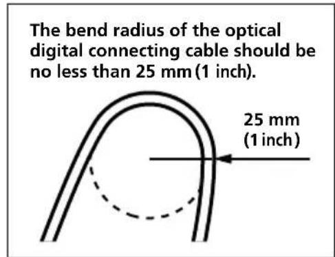
- When storing the system, attach the cap to the end of the plug and be careful not to fold or bend the optical digital connecting cable with a bend radius less than 25 mm (1 inch).
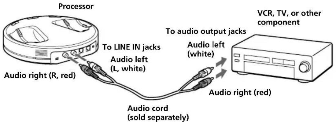
Connecting the processor to analog components
Use an audio cord (sold separately) to connect the audio output jacks on a VCR, TV, or other component to the LINE IN (L/R) jacks on the processor.
Connecting cables (sold separately)
Use the connecting cable (stereo mini-plug ↔ pin plug × 2) when connecting a stereo mini-jack (line out jack or headphone jack) to the LINE IN jacks.
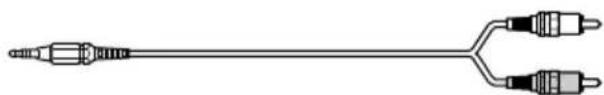
In this case, set the volume on the player at a medium level. Noise can occur if the volume on the player is set too low.
Setting the input level
If the volume is low using the analog input, set the ATT (attenuator) switch to "0 dB."
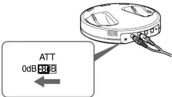
Setting Connected components
0 dB TV, portable components, and other components with a low output level
-8 dB Other components (initial settings)
Notes
- Be sure to lower the volume before setting the ATT switch.
- If audio input to the LINE IN jacks is distorted (sometimes, noise can be heard at the same time), set the ATT switch to “-8 dB.”
Listening to a Connected Component
Before starting, be sure to read “Connecting the Headphone System” (pages 15 to 17) and make the proper connections.
1 Turn on the component connected to the processor.
DVD device, digital satellite/TV receiver, or other audio or video component
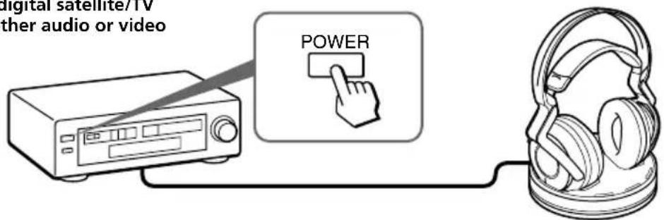
2 Remove the headphones from the processor.
The processor turns on automatically and the RF indicator blinks for about 5 seconds. The processor automatically detects the optimum frequency for transmission according to your room conditions. The RF indicator lights up when emission from the processor starts. Then the DECODE MODE indicator lights up, depending on the audio signal input from the connected audio or video component and the setting of the EFFECT switch.
Signal transmission system
This unit employs a proprietary transmission system using 2.4 GHz frequency. You can enjoy non-compressed sound with this wireless system.
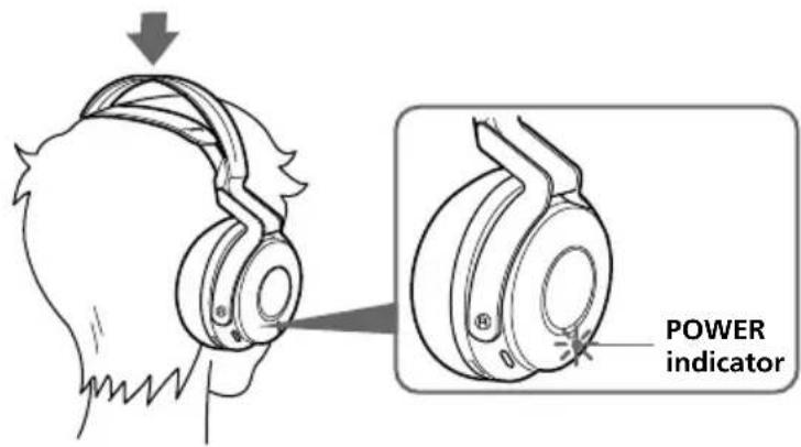
3 Put on the headphones.
The POWER indicator lights blue, and the headphones automatically turn on. Be sure to match the right and left side of the headphones with your ears and wear the headphones at the correct angle so that the Auto Power On/Off function works correctly. Sound is heard from the headphones about 3 seconds after you put on the headphones.
4 Slide the INPUT SELECT switch to select the component you want to listen to.
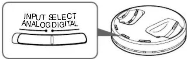
Position of switch Selected sound source
DIGITAL Sound of the component connected to DIGITAL IN jack.
ANALOG Sound of the component connected to LINE IN jacks.
Note
To listen to dual audio (MAIN/SUB) sound sources, connect to the LINE IN jacks, and then select the sound source you want to listen to on the player, TV, or other component.
5 Start playback of the component selected in step 4.
6 Slide the switch to select the desired sound field, EFFECT or COMPRESSION.
EFFECT switch
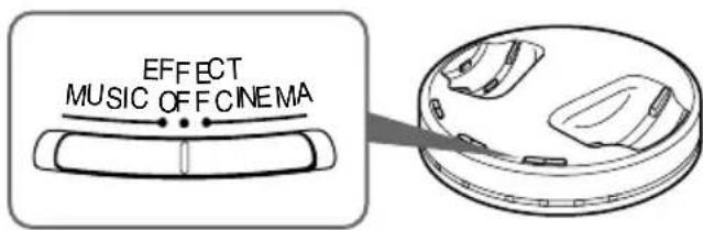
Position of switch Sound field and suitable sound source
OFF Normal playback of the headphones.
CINEMA Produces the kind of surround sound that is found in a typical movie theater. Suitable for movie sound sources.
MUSIC Produces the kind of sound field that would be found in a listening room with good acoustics. Suitable for music sources.
Note
The volume of the headphones may vary, depending on the input signal and the setting of the EFFECT switch.
(Continued)
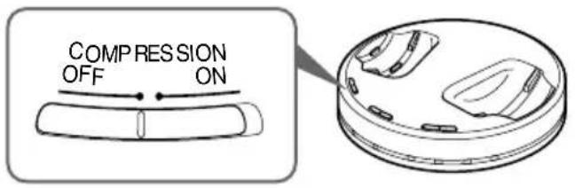
Position of switch Playback Effect
OFF When the EFFECT switch is selected, the sound mode changes to the selected effect.
ON This function maintains the overall level of program material: explosive sounds are attenuated while lower level sounds (dialog, etc.) are enhanced.
Illustration of the compression process
![graph LR A["explosion"] --> B["input signal"] B --> C["compression"] C --> D["output signal"] D --> E["explosion"] E --> F["dialogue"] F --> G["standard"] G --> H["whisper, background noise"] I["dynamic range"] --> J["whisper, background noise"] K["Startling level"] --> L["Easy to hear level"] M["Di…](/content/2026/03/468961/images/d73f373c387967f9e4bc822fd7720d8033b6cc0c366e75e319c47c8c5b08c7ce.jpg)
DECODE MODE indicators
The processor automatically identifies the format of the input audio signal and the corresponding indicator lights up. Switch the audio between Dolby Digital, DTS, MPEG-2 AAC, etc., on the connected equipment (DVD device, digital satellite/TV receiver, etc.).
• DOLBY DIGITAL: Input signal recorded in the DOLBY DIGITAL format.
- DOLBY PRO LOGIC II: Analog input signal, digital input PCM signal, or Dolby Digital 2-channel signal processed by DOLBY PRO LOGIC II.
(If the sound field is set to "OFF," it is not processed by DOLBY PRO LOGIC II.)
• DTS: Input signal recorded in the DTS format.
- MPEG-2 AAC: Input signal recorded in the MPEG-2 AAC format.
Note
If the equipment connected to the DIGITAL IN jack is not playing back (fast forwarding, rewinding, etc.), the DECODE MODE indicators may not light up correctly.
7 Adjust the volume.
Notes
- When watching films, be careful not to raise the volume too high in quiet scenes. You may hurt your ears when a loud scene is played.
- You may hear some noise when you disconnect the AC power adaptor from the processor before removing the headphones.
Transition time between modes
When sliding switches on the processor to change to new modes, the transition time between modes may vary. This is due to differences in system control between modes.
The headphones automatically turn off when they are removed
— Auto Power On/Off function
Do not pull up the self-adjusting band when not in use, as this will consume the battery power.

If a beep sound is heard from the headphones
A repeated beep sound is heard if reception conditions deteriorate when the headphones are outside the signal transmission area, or another wireless apparatus using 2.4 GHz frequency or microwave oven causes interference. If the beep sound does not stop after moving closer to the processor, let the processor detect the optimum frequency for transmission again following the procedure below.
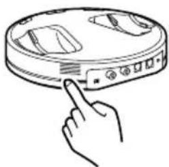
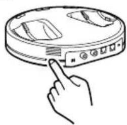
1 Press TUNE/ID SET on the processor once.
The RF indicator blinks and the processor detects the optimum frequency automatically. After detection is completed, the RF indicator lights up and emission starts.
2 Press TUNE/ID SET on the headphones once.
The headphones detect the frequency of the processor automatically. The beep sound stops when the headphones start receiving signals.

(Continued)
RF signal transmission area
The approximate RF signal transmission area from the processor is up to 30 m.
The processor detects the optimum frequency automatically when the headphones are removed from the processor. The sound may be interrupted if the headphones are out of RF signal transmission area or reception conditions deteriorate. In this case, move closer to the processor or press TUNE/ID SET on the processor and headphones to have them detect the optimum frequency again. See “If a beep sound is heard from the headphones” (page 21) on how to detect the optimum frequency.
Notes
- Because this system transmits signals at 2.4 GHz, sound may be interrupted if interference occurs. This is due to radio frequency characteristics, and is not a malfunction.
- Any noise you hear through the headphones may vary depending on the processor position and room conditions. It is recommended that you place the processor in a location that produces the clearest sound.
- Sound may be interrupted if the processor is used with other wireless apparatus using 2.4 GHz frequency, or a microwave oven.
If an audio signal is not input for 5 minutes
RF signal transmission from the processor automatically stops when an audio signal is not input for 5 minutes. The RF signals are automatically transmitted when an audio signal is input again. RF signal transmission may stop when an extremely low sound is input for about 5 minutes. If this happens, raise the volume of the connected audio or video component and lower the volume of the headphones. If signal noise is output from a component connected to the LINE IN jacks, RF signal transmission may not stop.
Tip
If RF signal transmission from the processor stops when an audio signal is not input for 5 minutes, the RF signals are automatically transmitted when an audio signal is input again. The RF indicator blinks and the processor detects the optimum frequency for transmission. If the transmission frequency changes after the RF indicator lights up and no sound is heard, press TUNE/ID SET on the headphones once and tune to the new frequency.
Notes
- The headphones should be used within the RF signal transmission area (see “RF signal transmission area”).
- The surround sound effect may not be obtained from sound sources that do not incorporate video, such as music CDs.
- This system simulates the average HRTF* common to most people. However, the effect can differ from person to person since the HRTF can vary between individuals.
* Head Related Transfer Function
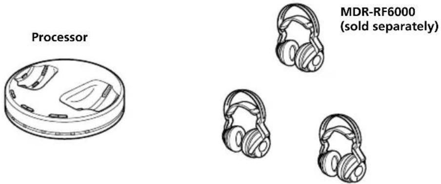
Using Additional Headphones
In this system, by using additional MDR-RF6000 wireless headphones (sold separately), more than one person can enjoy the surround sound experience wirelessly at the same time.
Charge additional headphones with the processor of this system.
* There is no limit to the number of headphones that can be used within the RF signal transmission area.
Notes
- The processor turns off automatically while charging. Remove these headphones from the processor when using other headphones.
- This unit is not compatible with headphones other than MDR-RF6000, since this unit employs a proprietary 2.4 GHz wireless digital transmission system.
When using additional headphones
Each processor has its own ID number. When using additional MDR-RF6000 wireless headphones (sold separately), be sure to set the processor's ID to that of the headphones, otherwise the headphones will not work.
1 Remove the headphones from the processor.
The processor turns on automatically.
2 Put on the headphones.
The headphones automatically turn on.
Note
Charge the battery of additional headphones before setting their IDs, or use commercially available (size AA) alkaline batteries.
3 Press and hold TUNE/ID SET on the processor and that on the headphones at the same time for more than 3 seconds.
A repeated beep sound is heard from the headphones and ID setting starts. When the sound changes to a continuous beep sound, the ID number is set for the headphones.


Replacing the Ear Pads
The ear pads are replaceable. If the ear pads become dirty or worn out, replace them as illustrated below. The ear pads are not commercially available. You can order replacements from the store where you purchased this system, or at your nearest Sony dealer.
1 Remove the old ear pad by pulling it off.
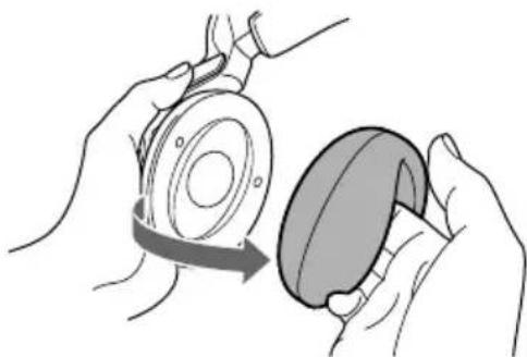
2 Place the new ear pad around the housing.
Troubleshooting
If you run into any problems using this headphone system, use the following checklist. Should any problem persist, consult your nearest Sony dealer.
Symptom Cause and remedy
| No sound | →Check the connection between the processor and the AV component.→Check that the signal is not being input to the digital out jack by mistake when digital input is selected.→Check that the connected AV component's optical digital output is set to "ON" when selecting digital input.→Turn on the AV component connected to the processor, and start the playback.→Check that the INPUT SELECT switch on the processor is set to the component you want to listen to.→If you connect the processor to an AV component using the headphone jack, raise the volume level on the connected AV component.→Make sure you are wearing the headphones correctly.→Raise the headphone volume.→The headphones' POWER indicator goes off.Charge the rechargeable battery if it is weak, or replace alkaline batteries with new ones. If the POWER indicator is still off after charging the battery, take the headphones to a Sony dealer.→You are trying to play a DTS audio track on a DVD device that does not support DTS.Either use a DVD device that supports DTS, or select a Dolby Digital or PCM audio track.→You are playing back a DVD disc recorded in DTS when DTS digital output setting for the DVD device (including game machines) is “OFF.”See the instruction manual of your DVD device, and change the DTS digital output setting to “ON.”→You are playing back a DVD disc recorded in DTS when the DVD device (including game machines) and the processor are analog-connected.Use the digital connection. (Analog sound may not be output from the DVD device.)→The processor's ID is not set for the additional headphones.→Additional headphones are being charged.Remove additional headphones from the processor. |
(Continued)
Symptom Cause and remedy
| Distorted or intermittent sound (sometimes with noise) | →Charge the rechargeable battery if it is weak, or replace alkaline batteries with new ones. If the POWER indicator is still off after charging the battery, take the headphones to a Sony dealer.→Check if there is any wireless apparatus using 2.4 GHz frequency, or a microwave oven in the vicinity.→Change the position of the processor.→When analog input is selected, change the ATT switch on the processor to "-8 dB."→If you connect the processor to an AV component using the headphone jack, lower the volume level on the connected AV component.→When using DTS audio sources, set the EFFECT switch on the processor to "CINEMA" or "MUSIC" mode (page 19, 20). |
| Low sound | →When analog input is selected, change the ATT switch on the processor to "0 dB."→If you connect the processor to an AV component using the headphone jack, raise the volume level on the connected AV component.→Raise the headphone volume. |
| Loud background noise | →Check if there is any wireless apparatus using 2.4 GHz frequency, or a microwave oven in the vicinity.→If you connect the processor to an AV component using the headphone jack, raise the volume level on the connected AV component.→Charge the rechargeable battery if it is weak, or replace alkaline batteries with new ones. If the POWER indicator is still off after charging the battery, take the headphones to a Sony dealer. |
| The sound cuts off | →The processor stops transmitting signals if 5 minutes passes and no signal has been input.·Set the ATT switch on the processor to "0 dB."·If you connect the processor to an AV component using the headphone jack, raise the volume level on the connected AV component. |
| The surround sound effect is not obtained | →Set the EFFECT switch on the processor to "CINEMA" or "MUSIC" mode (page 19, 20).→The audio being played is not a multi-channel signal.·The surround effect does not work for monaural sound sources. |
| The DOLBY DIGITAL indicator does not turn on | →The digital audio output setting for the DVD device (including game machines) may be set to "PCM."·See the instruction manual of your DVD device, and change the setting (such as "Dolby Digital/PCM" or "Dolby Digital") for usage with components having built-in Dolby Digital decoders.→Playback signals are not recorded in Dolby Digital format.→The audio for the chapter being played is not a Dolby Digital signal. |
Symptom Cause and remedy
| The DOLBY PRO LOGIC II indicator does not turn on | →The EFFECT switch on the processor is set to “OFF.”→Analog input signal, digital input PCM signal, Dolby Digital 2-channel signal or MPEG-2 AAC 2-channel signal is not input. |
| The DOLBY PRO LOGIC II indicator turns on | →The EFFECT switch on the processor is set to “CINEMA” or “MUSIC” mode.→Analog input signal, digital input PCM signal, Dolby Digital 2-channel signal or MPEG-2 AAC 2-channel signal is input. |
| The DTS indicator does not turn on | →The DTS digital output setting on the DVD device (including game machines) is set to “OFF.”• See the instruction manual of your DVD device, and change the DTS digital output setting to “ON.”→Playback signals are not recorded in DTS format.→The audio for the chapter being played is not a DTS signal.→The DVD device does not support DTS format.• Use a DVD device that supports DTS. |
| MPEG-2 AAC indicator does not light up. | →Playback signals are not recorded in MPEG-2 AAC format. |
| The battery cannot be charged | →Check if the CHG indicator turns on. If not, put the headphones on the processor correctly so that the CHG indicator turns on.→Dry batteries are installed.• Insert the supplied rechargeable nickel-metal hydride battery.→Rechargeable batteries other than the supplied are installed.• Insert the supplied rechargeable nickel-metal hydride battery.→The processor’s contact pin and headphones’ contact point are dusty.• Wipe them with a cotton bud, etc. |
| The CHG indicator blinks. | →⊕ and ⊖ of the rechargeable battery do not match those in the battery compartment correctly.• Insert the rechargeable battery with correct polarity.→The rechargeable battery is damaged.• Replace it with a new one. The rechargeable battery, type BP-HP2000, is not commercially available. You can order the battery from the store where you purchased this system, or at your nearest Sony dealer. |
| RF signal transmission does not stop. (when the INPUT SELECT switch on the processor is set to “ANALOG”) | →Signal noise is output from the connected analog component.• Unplug the connected analog component, or set the INPUT SELECT switch on the processor to "DIGITAL," and make sure playback of the component connected to the DIGITAL IN jack is stopped. |
(Continued)
Symptom Cause and remedy
| No signal from optical digital output | →No power supplied to the processor.·Connect the processor to a power source.→No playback sound from the connected external digital unit at the optical input jack.·Check that the external unit is playing back. |
| Bilingual sound cannot be selected when using digital input. (Both MAIN and SUB can be heard at the same time.) | →Connect the analog out to the LINE IN jacks, and select the sound on the connected component. |
| A repeated beep sounds. | →The headphones cannot receive the signal from the processor.·Move within the RF signal transmission area.·Check the connection of the processor, AC power adaptor, and AC outlet.·Check if there is any wireless apparatus using 2.4 GHz frequency, or a microwave oven around the processor and headphones.·Change the position of the processor.→There is no audio signal input for about 5 minutes and RF signals are not transmitted.·Input the audio signal to the processor and press TUNE/ID SET on the headphones once.→Additional headphones are being charged.·Remove the additional headphones from the processor. |
Precautions
On safety
- Do not drop, hit, or otherwise expose the processor or headphones to strong shock of any kind. This could damage the product.
- Do not disassemble or attempt to open any parts of the system.
On power sources and placement
- If you are not going to use the system for a long time, unplug the AC power adaptor from the AC outlet. When removing the plug, grip the AC power adaptor. Do not pull on the cord.
- Do not place the system in any of the following locations.
- Location exposed to direct sunlight, near a heater, or other extremely high-temperature location
- Dusty location
– On an unsteady or inclined surface - L ocation exposed to large amounts of vibration
- Bathroom or other high-humidity locations
On headphones
Act considerably
When the volume is too high, the sound leaks outside the headphones. Be careful not to raise the volume so high that it bothers people around you.
There is a tendency to raise the volume when using in noisy places. However, for reasons of safety, it is advised to keep the volume at a level whereby you can still hear sounds around you.
On cleaning
Use a soft cloth slightly moistened with mild detergent solution. Do not use solvents such as thinner, benzene or alcohol as these may damage the surface.
When the product breaks
- When the product breaks, or if a foreign object gets inside the unit, immediately turn off the power and consult your nearest Sony dealer.
- When taking the system to a Sony dealer, be sure to take both the headphones and processor.
Specifications
Digital surround processor (DP-RF6000)
Decoder functions Dolby Digital
Dolby Pro Logic II
DTS
MPEG-2 AAC
Virtual surround function
OFF
CINEMA
MUSIC
Compression function OFF
ON
Modulation System DSSS
Carrier wave frequency 2.412 \~ 2.462 GHz
Transmission distance Approx. 30 m (100 ft) of longest
Frequency response 12 - 22,000 Hz (digital input, sampling
frequency 48 kHz)
Distortion rate 1% or less (1 kHz)
Audio inputs Optical digital input
(rectangular-type) × 1
Analog input (pin jack
left/right) × 1
Audio output Optical digital output
(rectangular-type) × 1
Power requirements DC 9 V (from the
supplied AC power adaptor)
Dimensions
Approx. 182 × 38 ×
182 mm
(71 / 4× 11 / 2× 71 / 4in)
(w/h/d)
Mass Approx. 345 g
(12.17 oz)
Wireless stereo headphones (MDR-RF6000)
Playback frequency range
12 - 22,000 Hz
Power requirements Rechargeable nickel-
metal hydride battery
(supplied) or
commercially
available (size AA)
alkaline batteries
Mass Approx. 360 g
(12.7 oz) (including
the supplied
rechargeable nickel-
metal hydride battery)
Supplied accessories
AC power adaptor (9 V) (1)
Rechargeable nickel-metal hydride battery BP-HP2000 (2,100 mAh) (1)
Optical digital connecting cable (optical rectangular plug optical
rectangular plug, 1.5 m) (1)
Operating Instructions (this manual) (1)
Recommended accessories
Optical digital connecting cable
POC-15AB (1.5 m) (mini-plug ↔ rectangular plug)
Design and specifications are subject to change without notice.
AVERTISSEMENT
Pile rechargeable nickel-hydrure métallique BP-HP2000 (1)
Remarque
Chargement

* H ead Related Transfer Function
Alimentation Pile rechargeable
nickel-hydrure
rechargeable nickel-
hydrure métallique
fournie)
Accessoires fournis
Pile rechargeable nickel-hydrure
métallique BP-HP2000 (2 100 mAh) (1)
Pila recargable de hidruro de níquel-metal BP-HP2000 (1)


Nota
Carga
(continuación)


- DIGITAL SURROUND HEADPHONE SYSTEM
- TO REDUCE THE RISK OF FIRE OR ELECTRIC SHOCK, DO NOT EXPOSE THIS APPARATUS TO RAIN OR MOISTURE
- FOR THE CUSTOMERS IN THE USA
- OWNER'S RECORD
- NOTE
- NOTICE FOR THE CUSTOMERS IN THE U.S.A
- FOR THE CUSTOMERS IN THE CANADA
- RECYCLING NICKEL METAL HYDRIDE BATTERIES
- TABLE OF CONTENTS
- MAIN FEATURES
- THE DIGITAL SURROUND PROCESSOR FOR THIS SYSTEM INCORPORATES THE DOLBY DIGITAL DECODER, THE DOLBY PRO LOGIC II DECODER, THE DTS DECODER AND THE MPEG-2 AAC DECODER
- AAC PATENT MARKING
- CHECKING THE COMPONENTS AND ACCESSORIES
- LOCATION AND FUNCTION OF PARTS
- FRONT PANEL OF THE PROCESSOR
- REAR PANEL OF THE PROCESSOR
- 1 TUNE/ID SET BUTTON
- 2ATT (ATTENUATOR) SWITCH
- 3 LINE IN JACKS
- 4 DIGITAL IN JACK
- 5 DIGITAL OUT JACK
- 6 DC IN 9V JACK
- HEADPHONE PART DESCRIPTIONS
- CHARGING THE SUPPLIED RECHARGEABLE NICKEL-METAL HYDRIDE BATTERY
- INSERTING THE SUPPLIED RECHARGEABLE NICKEL-METAL HYDRIDE BATTERY
- CHARGING
- NOTES
- 3 REST THE HEADPHONES ON THE PROCESSOR SO THAT THE HEADPHONES' CONTACT POINT MEETS THE PROCESSOR'S CONTACT PIN, AND MAKE SURE THAT THE CHG INDICATOR LIGHTS UP
- IF THE CHG INDICATOR IS NOT LIT
- TO RECHARGE THE HEADPHONE BATTERY AFTER USE
- CHECKING THE BATTERY POWER
- USING THE HEADPHONES WITH ALKALINE BATTERIES (SOLD SEPARATELY)
- NOTES ON BATTERIES
- CONNECTING THE HEADPHONE SYSTEM
- CONNECTING THE PROCESSOR TO DIGITAL COMPONENTS
- DTS
- CONNECTING CABLES (SOLD SEPARATELY)
- NOTES ON OPTICAL DIGITAL CONNECTING CABLE
- CONNECTING THE PROCESSOR TO ANALOG COMPONENTS
- SETTING THE INPUT LEVEL
- SETTING CONNECTED COMPONENTS
- LISTENING TO A CONNECTED COMPONENT
- BEFORE STARTING, BE SURE TO READ “CONNECTING THE HEADPHONE SYSTEM” (PAGES 15 TO 17) AND MAKE THE PROPER CONNECTIONS
- 1 TURN ON THE COMPONENT CONNECTED TO THE PROCESSOR
- 2 REMOVE THE HEADPHONES FROM THE PROCESSOR
- SIGNAL TRANSMISSION SYSTEM
- 3 PUT ON THE HEADPHONES
- 4 SLIDE THE INPUT SELECT SWITCH TO SELECT THE COMPONENT YOU WANT TO LISTEN TO
- POSITION OF SWITCH SELECTED SOUND SOURCE
- 5 START PLAYBACK OF THE COMPONENT SELECTED IN STEP 4
- 6 SLIDE THE SWITCH TO SELECT THE DESIRED SOUND FIELD, EFFECT OR COMPRESSION
- EFFECT SWITCH
- POSITION OF SWITCH SOUND FIELD AND SUITABLE SOUND SOURCE
- POSITION OF SWITCH PLAYBACK EFFECT
- ILLUSTRATION OF THE COMPRESSION PROCESS
- DECODE MODE INDICATORS
- 7 ADJUST THE VOLUME
- TRANSITION TIME BETWEEN MODES
- THE HEADPHONES AUTOMATICALLY TURN OFF WHEN THEY ARE REMOVED
- AUTO POWER ON/OFF FUNCTION
- IF A BEEP SOUND IS HEARD FROM THE HEADPHONES
- 1 PRESS TUNE/ID SET ON THE PROCESSOR ONCE
- 2 PRESS TUNE/ID SET ON THE HEADPHONES ONCE
- RF SIGNAL TRANSMISSION AREA
- IF AN AUDIO SIGNAL IS NOT INPUT FOR 5 MINUTES
- TIP
- USING ADDITIONAL HEADPHONES
- WHEN USING ADDITIONAL HEADPHONES
- 1 REMOVE THE HEADPHONES FROM THE PROCESSOR
- 2 PUT ON THE HEADPHONES
- 3 PRESS AND HOLD TUNE/ID SET ON THE PROCESSOR AND THAT ON THE HEADPHONES AT THE SAME TIME FOR MORE THAN 3 SECONDS
- REPLACING THE EAR PADS
- TROUBLESHOOTING
- PRECAUTIONS
- ON SAFETY
- ON POWER SOURCES AND PLACEMENT
- ON HEADPHONES
- ACT CONSIDERABLY
- ON CLEANING
- WHEN THE PRODUCT BREAKS
- SPECIFICATIONS
- DIGITAL SURROUND PROCESSOR (DP-RF6000)
- WIRELESS STEREO HEADPHONES (MDR-RF6000)
- SUPPLIED ACCESSORIES
- RECOMMENDED ACCESSORIES
- AVERTISSEMENT
- REMARQUE
- CHARGEMENT
- ACCESSOIRES FOURNIS
- CARGA
Brand : SONY
Model : MDRDS6000
Category : Earphones