
Platinum Cross Sprinter - Electric bike TUNTURI - Free user manual and instructions
Find the device manual for free Platinum Cross Sprinter TUNTURI in PDF.

| Product type | Elliptical bike (cross trainer) |
| Brand | Tunturi |
| Model | Platinum Cross Sprinter |
| Dimensions (L x H x W) | 174 cm x 60 cm x 166 cm |
| Weight | 110 kg |
| Max user weight | 150 kg |
| Console power | 3 AA alkaline batteries (supplied) or rechargeable NiCd |
| Display | Time, distance (miles or km), RPM (cadence), heart rate |
| Heart rate receiver | Compatible with Polar (coded transmitter) |
| Console functions | Progressive counting, countdown, quick start, reset |
| Resistance | Factory-set brake, power based on speed and torque |
| Standards | EN-957 class A, EU directives (EMC, low voltage) |
| Assembly | Requires 2 people, tools included, detailed instructions in the manual |
| Routine maintenance | Wipe with a damp cloth after each use; do not use harsh detergents |
| Monthly check | Ensure all fastenings are tight |
| Lubrication | Not necessary, but if noise occurs, use a natural lubricant (vegetable or soy-based oil) |
| Operating conditions | Indoor only, temperature 10°C to 35°C, max humidity 90% |
| Storage | Dry place, away from dust and temperature variations |
| Transport | Transport wheels, move with two people, do not transport on stairs using wheels |
| Spare parts | List provided in the manual, contact dealer for orders |
| Warranty | Does not cover damage due to failure to follow assembly, use, or maintenance instructions |
Frequently Asked Questions - Platinum Cross Sprinter TUNTURI
User questions about Platinum Cross Sprinter TUNTURI
0 question about this device. Answer the ones you know or ask your own.
Ask a new question about this device
Download the instructions for your Electric bike in PDF format for free! Find your manual Platinum Cross Sprinter - TUNTURI and take your electronic device back in hand. On this page are published all the documents necessary for the use of your device. Platinum Cross Sprinter by TUNTURI.
USER MANUAL Platinum Cross Sprinter TUNTURI
Important safety instructions 2
Console 3
Assembly 4
Moving and storage 9
Fitness -
Basics on exercising 9
Heart rate 9
Maintenance -
Maintenance 9
Management mode 10
Troubleshoot 10
Technical data 10
Product information -
Exploded view 74
Parts list 75
Welcome to the world of Tunturi exercising!
Your choice shows that you really want to invest in your well being and condition; it also shows you really value high quality, safe and motivating product as your training partner. Whatever your goal in training, we are certain this is the training equipment to get you there. You'll find information about using your exercise equipment and what makes for efficient training at Tunturi's website at www.TUNTURI.COM
Important Safety Instructions
This owner's manual is an essential part of your training equipment: reading all instructions in this manual before you start using this appliance. The following precautions must always be followed.
Note about your health
Before you start any training, consult a physician to check your state of health.
If you experience nausea, dizziness or other abnormal symptoms while exercising, stop your workout at once and consult a physician.
- To avoid muscular pain and strain, begin each workout by warming up and end it by cooling down (slow pedaling at low resistance). Don't forget to stretch at the end of the workout.
Note about the exercise environment
The equipment is not to be used outdoors.
- Place the equipment on a firm, level surface. Place the equipment on a protective base to avoid any damages to the floor beneath the equipment.
Make sure that the exercising environment has adequate ventilation. To avoid catching cold, do not exercise in a draughty place.
- In training, the equipment tolerates an environment measuring +10ircC to +35ircC . The equipment can be stored in temperatures ranging between -15ircC and +40ircC . Air humidity in the training or storage
environment must never exceed 90% .
- Keep hands away from all moving parts.
Note about the equipment
If children are allowed to use the equipment, they should be supervised and taught to use the equipment properly, keeping in mind the child's physical and mental development and their personality.
Before you start using the equipment, make sure that it functions correctly in every way. Do not use faulty equipment.
- Press the keys with the tip of the finger; your nails may damage the key membrane.
- Never lean on the interface.
- Never remove the side covers. Do not step on the frame casing.
Only one person may use the equipment at a time.
- Hold the stationary handlebar for support when getting on or off the equipment.
- Wear appropriate clothing and shoes when exercising.
- Project the meter from sunlight and always dry the surface of the meter if there are any drops of sweat on it.
Further information on warranty terms can be found in the warranty booklet included with the product.
- Please note that the warranty does not cover damage due to shipping or negligence of adjustment or maintenance instructions described in this manual.
The equipment must not be used by persons weighing over 150kg
Make sure the equipment is unplugged before carrying out any assembly or maintenance procedures.
- Do not attempt any servicing or adjustments other than those described in this guide. Everything else must be left to someone familiar with the maintenance of electromechanical equipment and authorized under the laws of the country in question to carry out maintenance and repair work.
- Never drop or insert any object into any openings.
SAVE THIS INSTRUCTION MANUAL
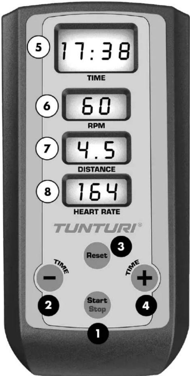
Console
The power for the console is provided by 3 AA alkaline batteries (provided) and will operate on rechargeable NiCd AA batteries. Once the batteries are installed the console will power on, the Time window will display the total usage time, the Distance window will display the total usage distance reading and the RPM window will display the software version. The usage time shows how long the elliptical has been in use and the distance shows how many virtual miles the elliptical has gone.
If the console does not detect a speed signal, or key activations, it will go to sleep to protect battery life. To wake the console up you can press any key.
Function keys
- Start/Stop: Starts and stops the program timer.
- Time-(Down): Used to set workout time before the start key is pressed. The down key will decrease the time setting by 1 minute for each key press. The time will change more rapidly when the key is held down for 2 seconds. The key is also used to switch the time reading to count down (remaining time).
- Reset: Performs a complete reset of the console.
- Time + (up): Used to set workout time before the start key is pressed. The up key will increase the time setting by 1 minute for each key press. The time will change more rapidly when the key is held down for 2 seconds. The key is also used to switch the time reading to count up ( elapsed time).
Display
- Time: Displays workout time two ways; either count up (accumulated time) or count down (remaining time), depending on your preference selected before starting the timer.
- RPM: Displays the current pedaling speed as Revolutions Per Minute.
- Distance: Displays virtual distance traveled in miles or kilometers (units selected through Management Mode, see page 9 for details).
- Heart Rate: Displays heart rate in beats per minute when a heart rate chest belt transmitter is worn and detected by the console. The heart rate receiver is compatible with Polar coded transmitters.
Operation
Power the console on by pressing any key.
- Enter Quick start operation by simply pressing the start key. The time will count up from zero.
- You may set a workout time by using the Time up and down keys. When you press the Start key the time will count down to zero from the set time. After pressing start you can use the up and down keys to switch the time to count up or count down.
- Press the start/stop button to Pause the timer and also to resume the timer when it is in Pause mode.
- Press the Reset key to reset all the data.
- For Heart Rate readings you must wear a heart rate transmitter. The console will pick up the transmitter signal and display your heart rate automatically.

= Function key

=Display
Assembly
Start by unpacking the equipment. The detailed assembly instructions can be found at the back of this guide. Follow the instructions in given order.
Before assembly, check the contents of the package. If a part is missing, please contact your dealer with the model, equipment serial no. and spare part no. of the missing part. You'll find a spare part list at the back of this guide. The hardware kit contents are marked with * in the spare parts list. The directions left, right, front and back are defined as seen from the exercising position. Keep the assembly tools, as you may need them e.g. for adjusting the equipment. Note that two people are needed for the assembly.
The packaging includes a silicate bag for absorbing moisture during storage and transportation. Please dispose of the bag once you have unpacked the equipment. Allow at least 100 cm of clearance around the equipment. We also recommend opening the package and assembling the product on a protective base.
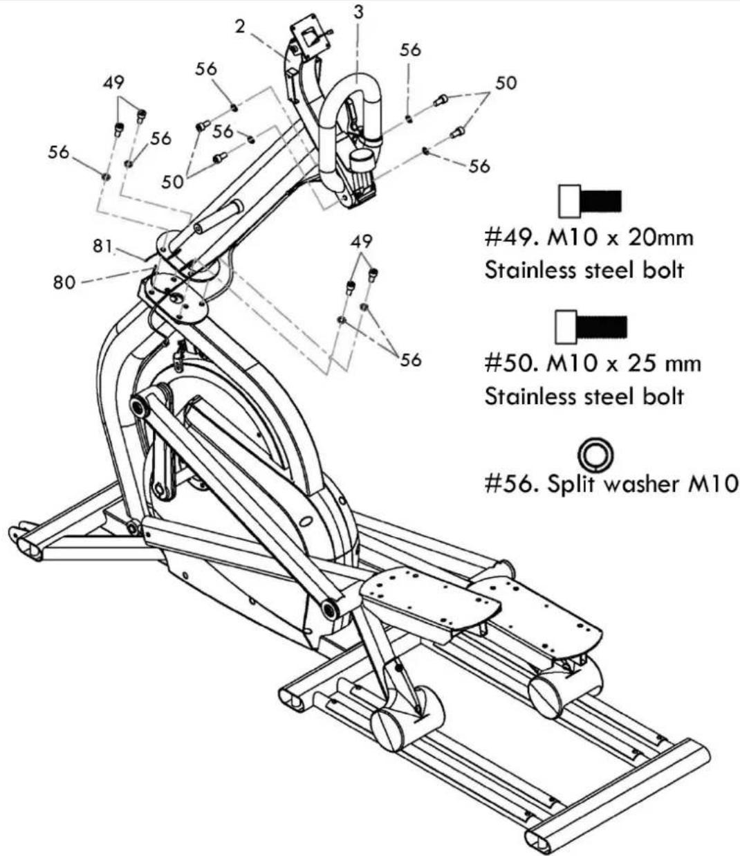
Step 1: Upright tube
- The tension adjustment cable and speed sensor wire are pre-installed to the upright tube and main frame so be careful not to pull too hard on the upright tube during assembly to avoid damaging them. Connect the two speed sensor wires together.
- Lift the upright tube (2) into place and align it so that the locating pins in the mounting plate are set into the holes in the mating plate of the main frame. Be careful not to pinch the speed sensor wire between the upright tube and the main frame plates during assembly.
- Secure the upright tube in place with the four M10 x 20mm stainless steel bolts (49) and M10 split washers (56). Make sure the bolts are securely tightened.
- Install the fixed handlebars (3) to the upright tube with four M10 x 25mm stainless steel bolts (50) and M10 split washers (56). Make sure the bolts are securely tightened.
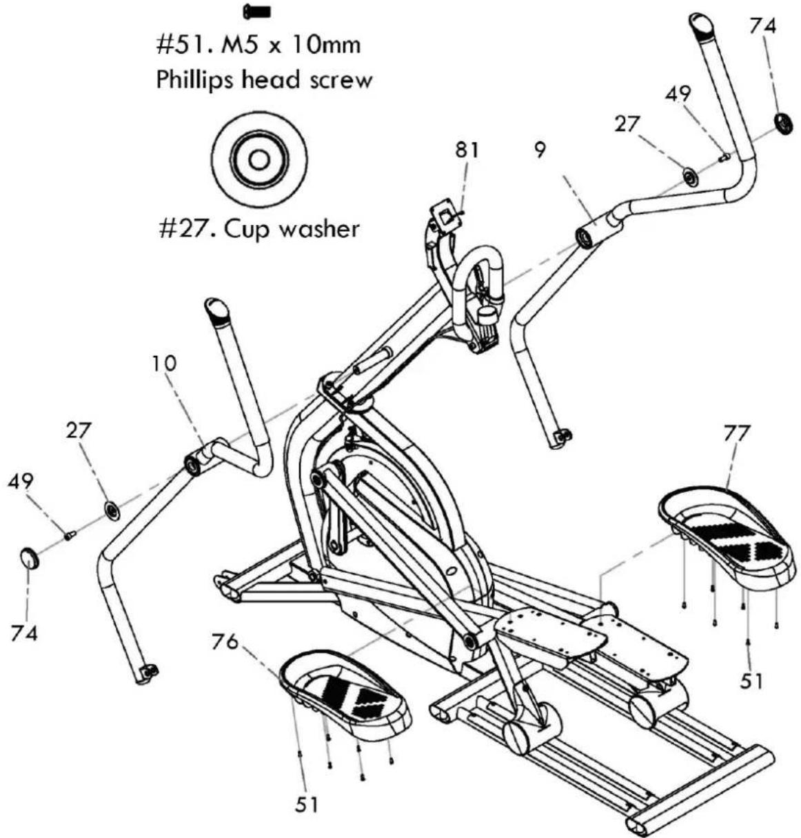
Step 2: Moving handlebars & pedals
- Slide the two moving handlebars (9 & 10) onto the upright tube axle. There is a left and right handlebar so make sure you assemble the correct one on each side. Do not force the handlebars onto the axle or use a hammer as damage to the bearings could occur. The moving handlebars have been previously installed at the factory and should fit properly, although it is a snug fit.
- Secure the handlebars in place with the M10 x 20mm stainless steel bolts (49) and cup washers (27) and tighten. Snap the endcaps (74) over the cup washers.
- Connect the clear drain hoses and install the foot pedals (76 left, 77 right) with twelve M5 x 10mm
2.

49.M10×20mm
Stainless steel bolt

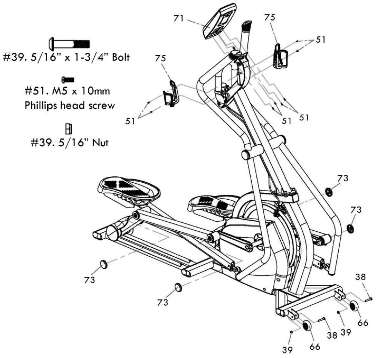
Step 3: Console
- Assemble the transport wheels (66) with the two 5 / 16 × 1 - 3 / 4 bolts (38) and 5 / 16 nuts (39)
- Unpack the console and install the 3 AA batteries. Connect the speed sensor wire into the white two pin connector accessed through the opening in the back of the console. Mount the console onto the console plate and secure with four M5 x 10mm screws (51).
- Secure the two bottleholders (75) to the upright tube with four M5 x 10mm screws (51)
- Snap the four end caps [73] onto the cup washers on the left & right pedal tube assemblies.
3.
Step 4: Moving handlebars
- Assemble the bracket at the bottom of the moving handlebars to the rod ends on the pedal tubes using the M10 x 38mm shoulder bolts (61) and the M10 nuts (62). Tighten securely.
4.
61.M10×38mm
Shoulder bolt

62.M10 nut

Step 5: Height adjustment screws & End caps
-
Tilt the elliptical to one side and put something under the unit for support and install the three height adjustment screws (65) for that side. Tilt the unit to the other side and install those three height adjustment screws (65). Level the elliptical once it is positioned where it will be used. Screw the two middleheight adjustment screws all the way in and the front and rear levelers all the way in, then back them out about two or three turns. Level the unit using only the front and rear adjustment screws first, then adjust the middle adjustment screws so they touch the floor. Make sure to lock the adjustment screws when finished.
-
Press the six plastic end caps (72) into the oval stabilizer tubes.

5.
Moving and storage
Please follow these instructions when carrying and moving the equipment about, because lifting it incorrectly may strain your back or risk other accidents:
- For transportation or moving of the device, two grown-ups are needed. Remain standing in front of the device on each side and take a sturdy grip at the handles. Lift the front of the device so as to lift the rear of the device on the wheels. Move the device and carefully put it down to its new place.
To prevent the equipment malfunctioning, store in a dry place with as little temperature variation as possible and protected from dust.

NOTE!
Transport the equipment with caution over uneven surfaces, for example over a step. The equipment should never be transported upstairs using the wheels over the steps, instead it must be carried. We recommend that you use a protective base when transporting the equipment.
Basics on exercising
Working out using an elliptical trainer is excellent aerobic exercise, the principle being that the exercise should be suitably light, but of long duration. Aerobic exercise is based on improving the body's maximum oxygen uptake, which in turn improves endurance and fitness. The ability of the body to burn fat as a fuel is directly dependent on its oxygen-uptake capacity. Aerobic exercise should above all be pleasant. You should perspire, but you should not get out of breath during the workout. You must, for example, be able to speak and not just pant while pedaling.
You should exercise at least three times a week, 30 minutes at a time, to reach a basic fitness level. Maintaining this level requires a few exercise sessions each week. Once the basic condition has been reached, it is easily improved simply by increasing the number of exercise sessions. Exercise is always rewarding for weight loss, because it is the only way of increasing the energy spent by the body. This is why it is always worthwhile to combine regular exercise with a healthy diet. A dieter should exercise daily, at first 30 minutes or less at a time, gradually increasing the daily workout time to one hour.
You should start slowly at a low pedaling speed and low resistance, because for an overweight person strenuous exercise may subject the heart and circulatory system to excessive strain. As fitness improves, resistance and pedaling speed can be increased gradually. Exercise efficiency can be measured by monitoring the pulse. The pulse meter helps you monitor your pulse easily during exercise, and thus to ensure that the exercise is sufficiently effective but not over-strenuous. Start your workout with slow tempo and low resistance. Gradually increase tempo and resistance according to your own condition. Keep your head up and neck long in order to avoid stress on your neck, shoulders and back. Keep also your back straight. Make sure that your feet are centered on the foot pedals and that your hips, knees, ankles and toes are facing forward. Keep your body weight centered over your lower body regardless of whether you lean forward or stand upright. Stop your workout by gradually decreasing tempo and resistance.
Don't forget to stretch afterwards. To strengthen cardiovascular system, maintain low resistance but high tempo. Exercising with higher resistance and slow tempo
strengthens correspondingly your back and hips. over your lower body regardless of whether you lean forward or stand upright. Stop your workout by gradually decreasing tempo andresistance.
Don't forget to stretch afterwards. To strengthen cardiovascular system, maintain low resistance but high tempo. Exercising with higher resistance and slow tempo strengthens correspondingly your back and hips.
Heart rate
No matter what your goal, you'll get the best results by training at the right level of effort, and the best measure is your own heart rate. The meter has a heart rate receiver compatible with Polar equipment, so you can also use Polar coded heart rate transmitter belts for heart rate measurement.

NOTE!
If you are fitted with a pacemaker, please consult a physician before using a heart rate transmitter belt.
The most reliable heart rate measurement is achieved with a telemetric device, in which the electrodes of the transmitter fastened to the chest transmit the pulses from the heart to the console by means of an electromagnetic field. If you want to measure your heart rate this way during your workout, moisten the grooved electrodes on the transmitter belt with water. Fasten the transmitter just below the chest with the elastic belt, firmly enough so that the electrodes remain in contact with the skin while exercising, but not so tight that normal breathing is prevented. If you wear the transmitter and belt over a light shirt, moisten the shirt slightly at the points where the electrodes touch the shirt. The transmitter automatically transmits the heart rate reading to the console up to a distance of about 1m . If the electrode surfaces are not moist, the heart-rate reading will not appear on the display. If the electrodes are dry, they must be moistened again. Allow the electrodes warm up properly to ensure accurate heart rate measurement. If there are several telemetric heart rate measurement devices next to each other, the distance between them should be at least 1.5m . Similarly, if there is only one receiver and several transmitters in use, only one person with a transmitter should be within transmission range. The transmitter is switched to an active state only when it is being used for measurement. Sweat and other moisture can, however, keep the transmitter in an active state and waste battery energy. Therefore it is important to dry the electrodes carefully after use.
When selecting training attire, please note that some fibers used in clothes (e.g. polyester, polyamide) create static electricity, which may prevent reliable heart rate measurement. Please note that a mobile phone, television and other electrical appliances form an electromagnetic field around them, which will cause problems in heart rate measurement.
Maintenance
The elliptical is practically maintenance free. To keep it so, keep it clean by wiping down the unit with a damp cloth after each use. Do not use harsh detergents. Every month check that all the hardware is securely tightened. Do not use the elliptical if any parts are loose or broken.
The wheels and aluminum tracks will need to be kept clean to prevent noise and maintain smoothness.
No lubrication should be necessary but if persistent noises from the wheels develop you can use a small amount of lubricant. Natural lubricants work well such as vegetable oil or soy based lubrication products like Biokleen from Ecoviva: http://www.ecoviva.com/htmI/soy-lube.php
Management mode
To enter the management mode press Start/Stop and Up keys simultaneously for 3 seconds
The time window will show the software checksum (for engineering use) then tests the LCD display by sequencing all segments on.
The next display shows total usage time in the time window, software version In Speed window and total usage distance in distance window.
- Press the Reset key for distance reading setting, use up & down keys to adjust: 0 = Kilometers, 1 = Miles
- Press the Reset key for distance per pedal revolution setting: 1.83 = 1.83 meters (6 feet) per pedal revolution. Adjust to desired setting by using up & down keys.
- Press start/stop to exit.
Troubleshooting
Despite continuous quality control, defects and malfunctions caused by individual components may occur in the equipment. In most cases it's unnecessary to take the whole device in for repair, as it's usually sufficient to replace the defective part.
If the equipment does not function properly during use, contact your Tunturi dealer/distributor immediately. Always give the model and serial number of your equipment. Please state also the nature of the problem, conditions of use and purchase date.
If you require spare parts, always give the model, serial number of your equipment and the spare part number for the part you need. The spare part list is at the back of this manual. Use only spare parts mentioned in the spare part list.
Technical data
| Length | 174 cm |
| Width | 61 cm |
| Height | 172 cm |
| Weight | 115kg |

The Tunturi Cross sprinter meets the requirements of the EU's EMC Directives on electromagnetic compatibility (89/336/EEC) and electrical equipment designed for use within certain voltage limits (73/23/EEC). This product therefore carries the CE label.
The Tunturi Cross sprinter meets EN precision and safety standards (Class A, EN-957, parts 1 and 9) for fitness devices. The precision of the capacity measurement is secured during manufacturing by adjusting the brake with a dynamometer. Calculation of exercise capacity is based on rotation speed and moment.
Due to our continuous policy of product development, Tunturi reserves the right to change specifications without notice.
NOTE!
The instructions must be followed carefully in the assembly, use and maintenance of your equipment. The warranty does not cover damage due to negligence of the assembly, adjustment and maintenance instructions described herein. Changes or modifications not expressly approved by Tunturi will void the user's authority to operate the equipment!
WE WISH YOU MANY ENJOYABLE TRAINING HOURS WITH YOUR NEW TUNTURI TRAINING PARTNER!
Installation -
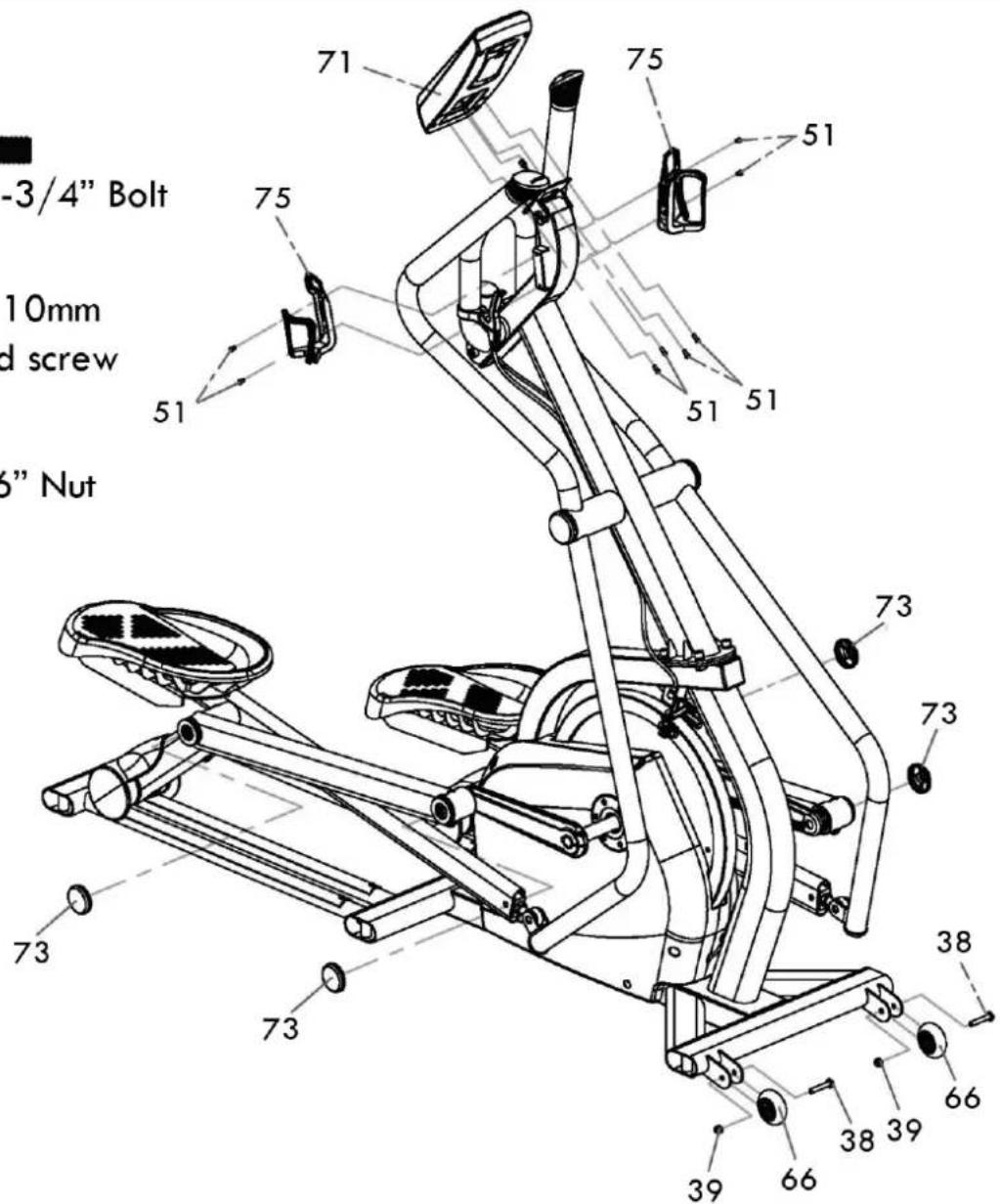
51.M5x10mm Phillips head screw
39.5/16" Nut
Stap 4: Bewegende handgrepen
49.M10x20mm Stainless steel bolt

- M5 x 10mm Phillips head screw
27.Cup washer
Passagio 3: Console
Paso 1: Tubo vertical
49.M10x20mm Stainless steel bolt

- M5 x 10mm Phillips head screw
27.Cup washer

Etape 3 : Console
Part description Q'ty
1 Main Frame 1
2Upright tube 1
3 Fixed handlebar Assembly 1
4 Pedal tube (R) 1
5 Pedal tube (L) 1
6 Inner pedal post (R) 1
7 Inner pedal post (L) 1
8 Flywheel Axle 1
9 Moving handlebar (R) 1
10 Moving handlebar (L) 1
11 Crank 2
12 U.I. Mounting Plate 1
13 Flywheel
13-1 Flywheel covers 2
14 0174_Pulley 2
15 Drive Axle 1
16 060 Pulley
17 Axle for drive pulley (L) 1
18 Axle for drive pulley (R) 1
19 Bearing Housing, Crank Axle 2
20 Side Case bracket 2
21 Set Collar 1
22 Tension Cable Pulley 1
23 Brake Magnet Mounting Arm 1
24 Tension Cable Retainers 2
25 Brake Mounting Bracket 1
26 Cup Washer For M8 Bolt 4
27 Cup Washer For M10 Bolt 2
28 Bearing (6005) 10
29 Bearing (6003) 16
30 Bearing (6203) 4
31 Rod End Bearing (M14 × P2.0) 2
32 Roller race 2.5T× 625mm 4
33 C Ring 17mm dia 6
34 C Ring 25mm dia 5
35 Wave Washer 17mm dia 12
36 Nyloc Nut M6-6t 2
37 Nyloc Nut M8 - 7t
38 Transp. wheel fixing Bolt 5 / 16 × 13 / 4 2
39 Transp. wheel fixing Nut 5/16" - 7† 2
40 Socket Head Cap Bolt M5 × 0.8 - 12mm 4
41 Socket Head Cap Bolt M5 × 0.8 - 20mm 1
42 Socket Head Cap Bolt M6 × 1.0 - 15mm 8
43 Socket Head Cap Bolt M6 × 1.0 - 25mm 1
44 Socket Head Cap Bolt M6 × 1.0 - 50mm 1
45 Socket Head Cap Bolt M8 × 1.25 - 12mm6
46 Socket Head Cap Bolt M8 × 1.25 - 15mm5
47 Socket Head Cap Bolt M8 × 1.25 - 35mm2
48 Socket Head Cap Bolt M8 × 1.25 - 70mm
49 Socket Head Cap Bolt M10 × 1.5 - 20mm 6 (Stainless steel)
50 Fixed handle bar fixing Bolt M10 x 1.5 - 4 25mm (Stainless steel)
51 Phillips Head Screw M5× 0.8 -10mm 40
52 Phillips Head Screw M6 × 1.0 - 10mm (Stainless steel)
53 Split Washer M5 4
54 Split Washer M6 8
55 Split Washer M8 3
56 Split Washer M10 (Stainless steel) 8
57 Nut M5 - 4t
58 Set screw M5 - 5mm 2
59 Flat Head Socket Screw M4 × 10mm 2 (Stainless steel)
Part description Q'ty
60 Idler Adj. Bolt M10 × 1.5 × 220mm 1
61 Inner pedal post fixing Bolt 14mm dia x 2 M10 x 38mm
62 Inner pedal post fixing Nut M10 - 8t 2
63 Riv-Nut 13mm dia × -M10 × 1.5 4
64 Woodruff Key (7× 7× 23mm) 2
65 Height adjustment screw 6
66 Transportation Wheel (65mm dia) 2
67 Round Side Case Insert 2
68 Side Cover (L) 1
69 Side Cover (R)
70 Square End Cap (50) 2
71 User Interface (U.I.)
72 Plastic End Cap 6
73 Pedal tube cover 4
74 Moving handle bar cover 2
75 Bottle Holder 2
76 Foot Pedal (L)
77 Foot Pedal (R) 1
78 Speed Magnet 1
79 Speed Sensor Mounting Bracket 1
80 Lower U.I. cable 950mm × 24AWG
81 Upper U.I. cable 1150mm
82 Nylon Washer ( 10× 14× 3T) 2
83 Roller cover 2
84 Moving handlebar end plug 2
85 Emergency Brake Lever 1
86 Emergency Brake Assembly 1
86-1 Emergency Brake Pad 2
87 Tension Knob Assembly 1
88 Emergency Brake Cable 1
89 Roller (PU 72mm dia) 4
90 Brake Return Spring (52× 3.5× 50mm) 1
91 Brake Magnet N35 (25 × 10mm) 2
92 Flywheel cover fixing screw M4× 12mm 6 Black
93 Flat washer 5× 10× 1.0T 4
94 Flywheel Set Collar (L) 1
95 Flywheel Set Collar (R) 1
96 Idler Wheel 2
97 35 Retaining Ring for Bore 2
98 Socket Head Cap Bolt M10 × 1.5 - 180mm
99 08×35×3.0T Flat Washer
100 Poly-V Drive Belt, 6PK 1000mm 2
101 6× 6× 16(mm)
102 Handgrip Foam 2
103 Handgrip End Cap 2
104 Cover Screw ( M4× 0.7 -15mm),Black
105 Phillips HeadScrew Driver 1
106 8th L Allen Wrench
107 17m/m Wrench
108 12th L Allen Wrench
109 5th L Allen Wrench
110 13m/m_Wrench
113 M6_Star Washer 2
Benelux
Accell Fitness Benelux
Koningsbeltweg 51
1329 AE ALMERE
The Netherlands
Tel: +31 36 5460050
Fax: +31 36 5460055
Scandinavia
Accell Fitness Scandinavia
Varusmestarintie 26
20361 TURKU
Finland
Tel: +358 10 2733 200
Fax: +358 2513 313
Germany
Accell Fitness North America Inc.
130 Hayward Ave, Suite 2
N2C 2E4
Kitchener, ON Canada
Tel. 1-888-388-6887
Fax: 1-519-576-2521
www.accellfitness.com
www.tunturi.com

- Fitness -
- Maintenance -
- Product information -
- Welcome to the world of Tunturi exercising!
- Important Safety Instructions
- Note about your health
- Note about the exercise environment
- Note about the equipment
- SAVE THIS INSTRUCTION MANUAL
- Console
- Function keys
- Display
- Operation
- Assembly
- Step 1: Upright tube
- Step 2: Moving handlebars & pedals
- 2.
- Step 3: Console
- 3.
- Step 4: Moving handlebars
- 4.
- Step 5: Height adjustment screws & End caps
- Moving and storage
- NOTE!
- Basics on exercising
- Heart rate
- Maintenance
- Management mode
- Troubleshooting
- Technical data
- WE WISH YOU MANY ENJOYABLE TRAINING HOURS WITH YOUR NEW TUNTURI TRAINING PARTNER!
- Installation -
- 39.5/16" Nut
- Stap 4: Bewegende handgrepen
- Passagio 3: Console
- Paso 1: Tubo vertical
- Etape 3 : Console
- Part description Q'ty
- Benelux
- Scandinavia
- Germany
Brand : TUNTURI
Model : Platinum Cross Sprinter
Category : Electric bike