
Syn Tech 4.075 - Washing machine Macrom - Free user manual and instructions
Find the device manual for free Syn Tech 4.075 Macrom in PDF.
| Product type | 4-channel audio amplifier |
| Brand | Macrom |
| Model | Syn Tech 4.075 |
| RMS Power (4 channels, 4 Ω) | 4 x 75 W |
| RMS Power (4 channels, 2 Ω) | 4 x 150 W |
| RMS Power (bridged, 4 Ω) | 2 x 300 W |
| IHF 202 Power | 650 W |
| Frequency response | 10 - 50,000 Hz (±1 dB) |
| Total harmonic distortion | 0.08% |
| Signal-to-noise ratio | >100 dB (IHF A weighted) |
| Input sensitivity | 200 mV - 4 V |
| Input impedance | 22 kΩ |
| Speaker impedance (stereo min.) | 2 Ω |
| Speaker impedance (mono min.) | 4 Ω |
| Power supply | 14.4 V DC (11-16 V allowed) |
| Dimensions (W x H x D) | 212 x 67 x 445 mm |
| Weight | 5.1 kg |
| Main features | 4/2 channel input mode selector, 4/3/2 channel output mode selector, Front/Rear crossover (Low-Pass, High-Pass, Flat), continuous frequency adjustment (30-600 Hz), gain adjustment, external bass control (EBC), Check Control status indicator |
| Maintenance and cleaning | Clean with a dry, soft cloth. Avoid chemicals. |
| Safety | Protection against overheating, overload and short circuit. Replace fuses with same amperage. |
| Spare parts and repairability | Contact an authorized MACROM dealer or support center for any repairs. |
Frequently Asked Questions - Syn Tech 4.075 Macrom
User questions about Syn Tech 4.075 Macrom
0 question about this device. Answer the ones you know or ask your own.
Ask a new question about this device
Download the instructions for your Washing machine in PDF format for free! Find your manual Syn Tech 4.075 - Macrom and take your electronic device back in hand. On this page are published all the documents necessary for the use of your device. Syn Tech 4.075 by Macrom.
USER MANUAL Syn Tech 4.075 Macrom
Front/Rear a 1 kHz < 0.08% THD+N a 4 ohms 4 x 75W
Front/Rear a 1 kHz<0.5% THD+N a 2 ohms 4 x 150W
Front/Rear a 1 kHz<0.5% THD+N Mono a 4 ohms 2 x 300W
Sensibilidad de salute Pre-Output 1:1
Pasa alto, Front y Rear (30-600)Hz
Macrom, who strive continually to achieve the ultimate in sound quality, have traditionally been a synonym for the very best in European sound and music reproduction. The fact that you have chosen this product means that you share our opinion. After reading this manual you will be in an even better position to appreciate all the advanced features in this new Amplifier. This Amplifier incorporates an exceptional set of technical features, and for this reason all signal sources, loudspeakers and interconnecting elements must also be of the very highest quality. We recommend the use of Macrom high quality main subassemblies, electronic crossovers, loudspeaker systems, connecting leads and accessories. Similarly, because integration of these products is an extremely complex task, we advise you to leave the installation of this amplifier to your authorised MACROM dealer.
This Amplifier has no commands or controls that can be adjusted by the user, so read this manual very carefully, to familiarise yourself with the special features and functions of your new MACROM product. If in any doubt, contact your authorised MACROM dealer.
PRECAUTIONS
- Just one faulty connection could damage the unit, so read the connection instructions provided in this manual very carefully.
- Connect the battery lead to the (+) battery terminal last of all, and only after having completed and checked all the other connections.
- Take care to install the amplifier in a position where both good air circulation and heat dissipation are guaranteed.
- The fuses must always be replaced with fuses of identical ampere rating in order to prevent serious damage to the components. You should also first have the voltage regulator of your car checked. Never attempt to repair the unit yourself. Entrust any necessary repairs to a MACROM distributor or your local MACROM service centre.
- To ensure the highest possible performance from this unit, try to obtain a temperature of between -10^ and +60^ inside your car before switching on the amplifier.
FEATURES
- 4/2 channel input mode switch
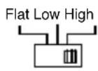
4/3/2 channel output mode switch - Front, flat, low-pass or high-pass filter switch
- Rear, flat, low-pass or high-pass filter switch
-
By-Pass Output
Continuous external control of the low frequency gain
Peak noise detector
Continuous frequency control
Continuous sensitivity control
Current feed with Mos-Fet -
" Check Control" status indicator
R emote-controlled start and stop
Gold-plated RCA input terminals
Professional gold-plated screw-type terminals
CONTROLS AND INDICATORS
1 - RCA Front input connectors: To connect the Pre output leads of the main unit to the amplifier input. These inputs control the final stages of the FRONT section.
2 - Adjustment of the gain of the Front Input: Adjusts input sensitivity of amplifier, which can vary between 200mV and 4V .
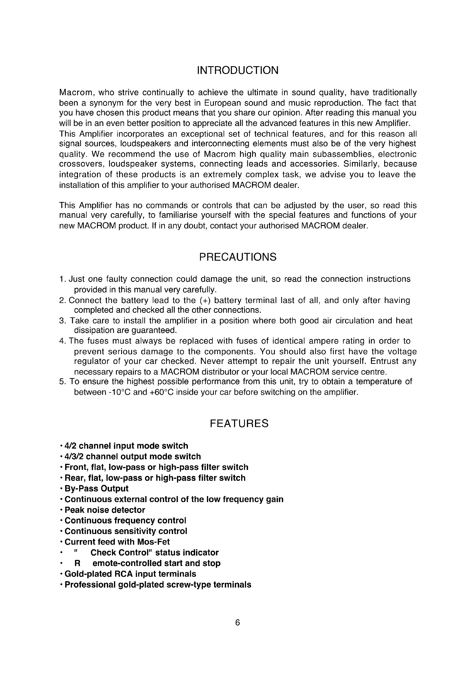
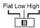
3 - Front Crossover switch: selects the output mode of the amplifier by activating the Low-pass or High-pass filter.
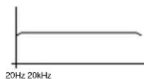
a) Flat: the amplifier will reproduce the complete audio range in relation to the signal applied to the input.


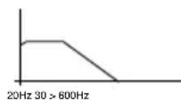
b) Low-pass: activation of the low-pass filter, i.e. determination of the finishing-point of the low frequencies present at the Front outputs.
c) High-pass: activation of the low-pass filter, i.e. determination of the starting-point of the high frequencies present at the Front outputs.

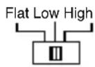
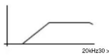
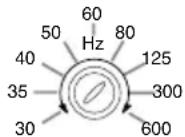
- Continuous adjustment/control of the Front Low-Pass or High-Pass frequencies: once the low-pass or high-pass filter is inserted, the crossover frequency can be adjusted in continuous mode between 30Hz and 600Hz .

5·4CH/2CH/ input mode switch: selects the input configuration of the amplifier in the following ways:
a) "4ch": requires connection of all four input channels, so that they can all function.
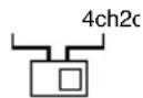
b) "2ch": If the main unit puts out two signals only, these must be connected to the Front input, to allow all four output channels to function. In this configuration the Rear inputs function as a By-pass output together with the Front input. In other words, you will obtain exactly the same signal as far as form and amplitude are concerned.

Note: Sensitivity adjustments will, in any case, remain independent.
6 - "4CH/3CH/2CH" Output mode switch: selects the output configuration of the amplifier in the following ways:
a) "4ch" configuration using 4 output channels: In this mode the amplifier can function with a double stereo system, front and rear.

b) "3ch" configuration using three output channels: In this mode the amplifier can function with a stereo system in Front and a "bridged" mono system in Rear.

c) "2ch" Configuration using 2 output channels: In this mode the amplifier can be used as a traditional 2-channel stereo amplifier with twice the normal power.

Note: With the configuration "2ch out" the sensitivity adjustments become independent. In other words, the Front section controls the sensitivity of the Left channel, while the Rear section controls the sensitivity of the Right channel.
Hence, if the crossover has to be activated, only the crossover of the Rear section will be activated, and consequently only its control for frequency adjustment will be active.
CONTROLS AND INDICATORS
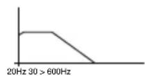
7 - Rear Crossover switch: select the output mode of the amplifier by activating the LowPass or High-Pass filter.
a) Flat: the amplifier will reproduce the entire audio range in relation to the signal applied at the input.

b) Low-Pass: activation of the low-pass filter, i.e. determination of the finishing-point of the low frequencies present at the Rear outputs.
c) High-pass: activation of the low-pass filter, i.e. determination of the starting-point of the high frequencies present at the Rear outputs.
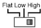
8·Continuous adjustment of the Rear Low-Pass or High-Pass Frequencies: once the high-pass or low-pass filter is inserted, the crossover frequency can be adjusted between 30 Hz and 600 Hz in continuous mode.
- Adjustment of the Rear Input gain: adjusts the input sensitivity of the amplifier, which varies from 200mV to 4V .

10 -Rear RCA input connectors: Connect the Pre output leads of your main unit to the amplifier input. These inputs will drive the final stages of the Rear section.
- Selector switch for the External Low Frequency Control: this switch activates or deactivates the external control of the low frequencies.
External Bass Control
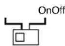
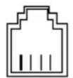
- Port for EBC connection: By means of the appropriate EBC control it is possible to act on the level of the low frequencies between 0dB and -40dB.
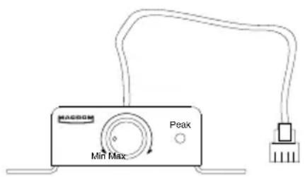
External Bass Control
CONTROLS AND INDICATORS
- Speaker connectors: Outputs for connecting the loudspeakers.
The amplifier allows the loudspeakers to be connected with a minimum impedance of 2 Ohm for a channel in stereo configuration, and with an impedance of 4 Ohm for a "bridged" mono connection.
If the 3 channel configuration is to be used, the total impedance should not exceed the minimum value of 2 Ohm.

Make sure that the polarity of the connection between the loudspeakers is correct. Do not allow inadequately insulated leads to come into contact with Ground, any metallic parts of the car, or with each other.
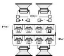
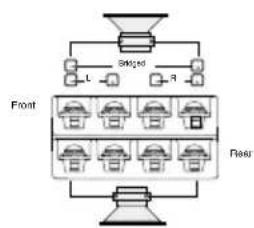
3-channel configuration 2-channel configuration 1-channel configuration
12 • Fuses: When replacing fuses, make sure that they are replaced with fuses of the same ampere rating. Use of the wrong type of fuse could seriously damage the components.
13 + BATT connector: Connect the positive "+" of the battery directly, by means of a fuse located nearby, and use a lead having a sufficiently large cross-section to allow passage of the current. Do not connect this terminal to the car's own electrical circuit.
14 - REMOTE-ON connector: Connect this to the remote-on start-up output lead (remote starting switch) or to the automatic antenna wire running from the main unit. It will now be possible to turn the amplifier on and off from the main unit.
15 · GND connector: Attach this Ground connector, using a lead of adequate section, to a clean point on any metallic part of the car chassis, if possible to an already-installed screw. Never attach this clamp directly to the negative point of the battery, which could give rise to an unpleasant buzzing noise while the car is being driven.
16 - Check control indicator: This LED indicates the amplifier functioning status.
WHITE: The unit is switched off
GREEN: The amplifier is functioning perfectly
RED: the unit is in a state of protection.
The amplifier is equipped with three protection devices:
-
Overheating: If errors have been made during installation, and the amplifier overheats, the unit will enter into a state of protection before any damage can occur. Once the temperature returns to normal and the errors have been rectified, the unit will automatically start to function normally once again.
-
Overloading: If several loudspeakers have been connected to the amplifier and the total impedance drops below the 1 Ohm limit that it can handle, the amplifier goes into a state of protection. The main unit will have to be switched off and on again in order to restore the amplifier to normal functioning.
-
Short circuit in an output: In the case of a short circuit in the loudspeaker outputs, the unit will go into a state of protection to avoid serious damage to the final transistors. Normal functioning will be restored when the short circuit has been dealt with and the main unit switched on again.
TECHNICAL DATA
Power IHF 202 650W
RMS Power at (12.5 Volts DC)
Front/Rear at 1kHz < 0.08% THD+N at 4 Ohm 4 x 75 W
Front/Rear at 1kHz < 0.5% THD+N at 2 Ohm 4 x 150 W
Front/Rear at 1kHz < 0.5% THD+N Mono at 4 Ohm 2 x 300 W
Pre-Out Sensitivity 1:1
High pass, Front and Rear (30-600)Hz Low pass, Front and Rear (30-600)Hz Crossover slope 12 dB/Octave
Response in frequency +/- 1 dB 10 - 50.000 Hz
Total harmonic distortion 0.08%
Weighted IHF A Signal-Noise Ratio
Input sensitivity - Impedance
Loudspeaker impedances Stereo Mono
Power supply Weight Dimensions
100 dB 200-4000 mV/22 kOhm
Due to the continual incorporation of improvements in this product, the characteristics and design may be subject to variation without prior notice.
EINFUHRUNG

External Bass Control

External Bass Control
CONTROLES ET INDICATEURS
Passehaut,FrontetRear (30-600)Hz
Passe bas, Front et Rear (30-600) Hz
Pente de coupe 12 dB/Octave
External Bass Control
DATI TECNICI
Potenza IHF 202 650W
Potenza RMS a (12,5 Volts DC
Front/Rear @ 1 kHz < 0,08 % THD+N a 4 ohms 4 x 75W
Front/Rear @ 1 kHz < 0,5 % THD+N a 2 ohms 4 x 150W
Front/Rear @ 1 kHz < 0,5% THD+N Mono a 4 ohms 2 x 300W
External Bass Control

External Bass Control
CONTROSES INDICADORES

Brand : Macrom
Model : Syn Tech 4.075
Category : Washing machine