HI 50.A IX - Oven INDESIT - Free user manual and instructions
Find the device manual for free HI 50.A IX INDESIT in PDF.

User questions about HI 50.A IX INDESIT
0 question about this device. Answer the ones you know or ask your own.
Ask a new question about this device
Download the instructions for your Oven in PDF format for free! Find your manual HI 50.A IX - INDESIT and take your electronic device back in hand. On this page are published all the documents necessary for the use of your device. HI 50.A IX by INDESIT.
USER MANUAL HI 50.A IX INDESIT
Electrical connections
Description of the appliance, 5
Overall view
Control panel
Start-up and use, 6
Starting the oven
Using the cooking timer
Cooking modes, 7-8
Cooking modes
Practical cooking advice
Cooking advice table
HI 50.B
HI 50.B IX
HI 500.B
HI 500.B IX
HIN 550
HIN 550 IX
HIN 5S
HIN 5S IX
HI 50.A
HI 50.A IX
Hob, 9
Type of hob
Switching on the glass ceramic hob
Practical advice on using the glass ceramic hob
Precautions and tips, 10
General safety
Disposal
Respecting and conserving the environment
Maintenance and care, 11
Switching the appliance off
Cleaning the appliance
Cleaning the oven door
Replacing the light bulb
Assistance
! Before placing your new appliance into operation please read these operating instructions carefully. They contain important information for safe use, for installation and for care of the appliance.
! Please keep these operating instructions for future reference. Pass them on to possible new owners of the appliance.
Positioning
! Keep packaging material out of the reach of children. It can become a choking or suffocation hazard (see Precautions and tips).
! The appliance must be installed by a qualified person in compliance with the instructions provided. Incorrect installation may cause harm to persons, animals or may damage property.
Fitting the appliance
Use the appropriate cabinet to ensure that the appliance functions properly.
- The panels adjacent to the oven must be made of heat-resistant material.
- Cabinets with a veneer exterior must be assembled with glues which can withstand temperatures of up to 100°C.
- To install the oven under the counter (see diagram) and in a kitchen unit, the cabinet must have the following dimensions:
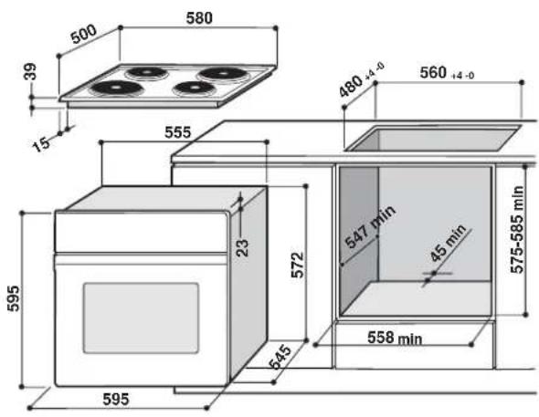
text_image
500 580 39 15 555 480 +4 -0 560 +4 -0 595 23 572 547 min 45 min 575-585 min 545 558 min 595! The appliance must not come into contact with electrical parts once it has been installed. The consumption indications on the data plate have been calculated for this type of installation.
Ventilation
To ensure good ventilation, the back panel of the cabinet must be removed. It is advisable to install the oven so that it rests on two strips of wood, or on a completely flat surface with an opening of at least 45 x 560 mm (see diagrams).
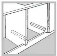
natural_image
Technical line drawing of a cabinet or enclosure with horizontal bars and floor lines (no text or symbols)
text_image
560 mm. 45 mm.Centring and fastening
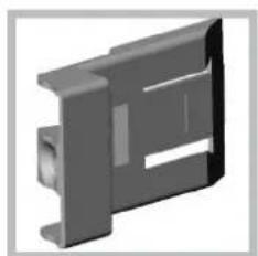
Position the 4 tabs on the side of the oven according to the 4 holes of the outer frame. Adjust the tabs according to the thickness of the cabinet side panel, as shown below:
natural_image
3D rendered mechanical component with cutouts and mounting holes (no text or symbols)thickness of 20 mm: take off the removable part of the tab (see diagram)
natural_image
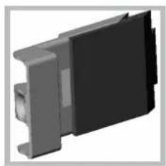
3D rendered mechanical component with black and gray sections (no text or symbols)thickness of 18 mm: use the first groove, which has already been set in the factory (see diagram)
natural_image
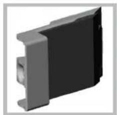
3D rendering of a mechanical component with black and gray sections (no text or symbols visible)thickness of 16 mm: use the second groove (see diagram)
Secure the appliance to the cabinet by opening the oven door and putting 4 screws into the 4 holes of the outer frame.
! All parts which ensure the safe operation of the appliance must not be removable without the aid of a tool.
Electrical connections
The cooker must be connected to the mains electricity supply. It is designed to operate with alternating current at the voltage and frequency indicated on the data plate (see the following page).
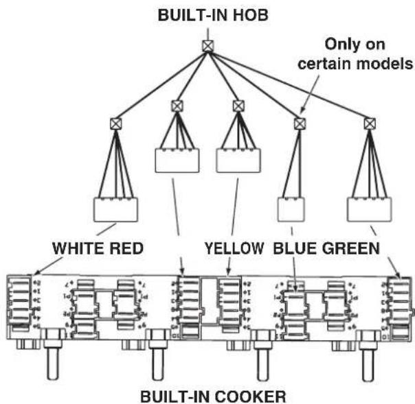
The hob is connected to the cooker using a special connector.
flowchart
graph TD
    A["BUILT-IN HOB"] --> B["White RED"]
    A --> C["Yellow"]
    A --> D["Blue GREEN"]
    A --> E["Only on certain models"]
    F["BUILT-IN COOKER"] --> G["White Red"]
    F --> H["Yellow"]
    F --> I["Blue GREEN"]
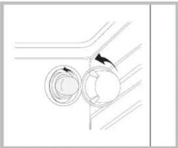
Replace the metal protection after performing all the necessary hob connections. If the hob is removed from its position, the red cap which was originally protecting the red connector must be replaced.
Fitting the power supply cable
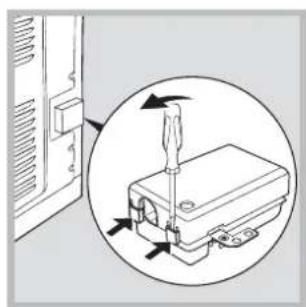
natural_image
Diagram showing a screwdriver inserted into a device component, with arrows indicating direction (no text or symbols present)-
Open the terminal board by inserting a screwdriver into the side tabs of the cover. Use the screwdriver as a lever by pushing it down to open the cover (see diagram).
-
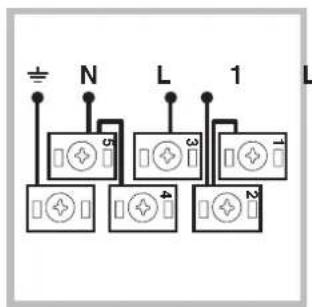
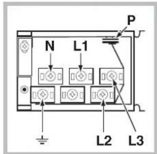
Install the power supply cable by loosening the cable clamp screw and the wire contact screws L-N- ± . Connect the wires to the corresponding terminals: the Blue wire to the terminal marked (N), the Brown wire to the terminal marked (L) and the Yellow Green wire to the terminal marked ± .
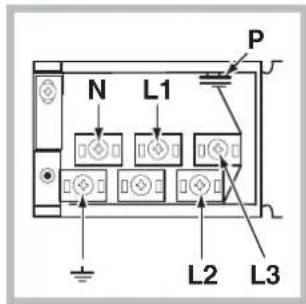
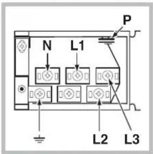
The terminal board is designed for a 400 V three-phase connection (see diagrams below).
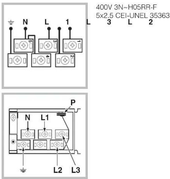
text_image
400V 3N~H05RR-F 5x2.5 CEI-UNEL 35363 N L 1 L 3 L 2 5 3 4 2 P N L1 L2 L3If the electrical system has other characteristics (see diagrams below), carry out the electrical connection using the connection supports provided in the box P.
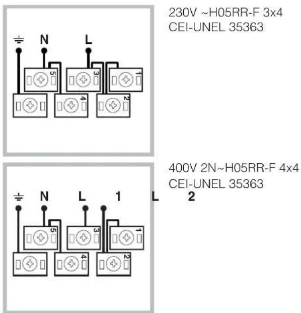
text_image
230V ~H05RR-F 3x4 CEI-UNEL 35363 400V 2N~H05RR-F 4x4 CEI-UNEL 35363-
Secure the power supply cable by fastening the clamp screw.
-
Close the cover of the terminal board.
Connecting the supply cable to the mains
Install a standardised plug corresponding to the load indicated on the data plate (see side).
The appliance must be directly connected to the mains using an omnipolar circuit-breaker with a minimum contact opening of 3 mm installed between the appliance and the mains, suitable for the load indicated and complying with current electrical regulations (the earthing wire must not be interrupted by the circuit-breaker). The supply cable must not come into contact with surfaces with temperatures higher than 50°C.
! The installer must ensure that the correct electrical connection has been made and that it is compliant with safety regulations.
Before connecting to the power supply, make sure that:
- The appliance is earthed and the plug is compliant with the law.
- The socket can withstand the maximum power of the appliance, which is indicated on the data plate (see below).
- The voltage must be in the range between the values indicated on the data plate (see below).
- The socket is compatible with the plug of the appliance. If the socket is incompatible with the plug, ask an authorised technician to replace it. Do not use extension cords or multiple sockets.
! Once the appliance has been installed, the power supply cable and the electrical socket must be easily accessible.
! The cable must not be bent or compressed.
! The cable must be checked regularly and replaced by authorised technicians only (see Assistance).
! The manufacturer declines any liability should these safety measures not be observed.
| DATA PLATE | |
| Dimensions | width 43.5 cmheight 32 cmdepth 40 cm |
| Volume | It. 56 |
| Electrical connections | voltage: 230V/400V~ 3N 50/60Hz maximum power absorbed 8450W |
| ENERGY LABEL | Directive 2002/40/EC on the label of electric ovens.Standard EN 50304Energy consumption for Forced convection heating mode:Multi-cookingDeclared energy consumption for Natural convection Class heating mode: — Convection |
 | This appliance conforms to the following European Economic Community directives:2006/95/EEC of 12/12/06 (Low Voltage) and subsequent amendments;- 2004/108/EEC of 15/12/04 (Electromagnetic Compatibility) and subsequent amendments;- 93/68/EEC of 22/07/93 and subsequent amendments.- 2002/96/EC and subsequent amendments. |
 | |
Overall view
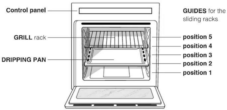
text_image
Control panel GRILL rack DRIPPING PAN GUIDES for the sliding racks position 5 position 4 position 3 position 2 position 1Control panel
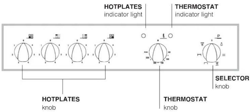
text_image
HOTPLATES indicator light THERMOSTAT indicator light HOTPLATES knob THERMOSTAT knob SELECTOR knob! The first time you use your appliance, heat the empty oven with its door closed at its maximum temperature for at least half an hour. Ensure that the room is well ventilated before switching the oven off and opening the oven door. The appliance may produce a slightly unpleasant odour caused by the burning away of protective substances used during the manufacturing process.
Starting the oven
- Select the desired cooking mode by turning the SELECTOR knob.
- Select the desired temperature with the THERMOSTAT knob. See the Cooking advice table for cooking modes and the suggested cooking temperatures (see Cooking Modes).
- When preheating is finished, the THERMOSTAT indicator light will stay on: place the food in the oven.
- You may do the following during cooking:
- change the cooking mode by turning the SELECTOR knob.
- change the temperature by turning the THERMOSTAT knob.
- stop cooking by turning the SELECTOR knob to the "0" position.
! Never put objects directly on the oven bottom to avoid damaging the enamel coating.
! Always place cookware on the rack(s) provided.
Cooling ventilation
In order to cool down the external temperature of the oven, some models are fitted with a cooling fan that blows out air between the control panel and the oven door.
! Once the cooking has been completed, the cooling fan remains on until the oven has cooled down sufficiently.
Oven light
It goes on when selecting 🙏 with the SELECTOR knob. It stays on when a cooking mode is selected.
Cooking modes
! A temperature value can be set for all cooking modes between 60°C and Max, except for
- GRILL (recommended: set only to MAX power level);
• GRATIN (recommended: do not exceed 200°C).

TRADITIONAL OVEN mode
Both the top and bottom heating elements will come on. With this traditional cooking mode, it is best to use one cooking rack only; if more than one rack is used, the heat will be distributed unevenly.

MULTI-COOKING mode
All the heating elements (top and bottom), as well as the fan, will come on. Since the heat remains constant throughout the oven, the air cooks and browns food uniformly. A maximum of two racks may be used at the same time.

TOP OVEN mode
The top heating element comes on. This mode can be used to brown food at the end of cooking.

GRILL mode
The top heating element comes on. The extremely high and direct temperature of the grill makes it possible to brown the surface of meats and roasts while locking in the juices to keep them tender. The grill is also highly recommended for dishes that require a high temperature on the surface: such as beef steaks, veal, rib steak, filets, hamburgers etc... Some grilling examples are included in the "Practical Cooking Advice" paragraph. Always cook in this mode with the oven door closed.

GRATIN mode
The top heating element, as well as the fan, will come on. This combination of features increases the effectiveness of the unidirectional thermal radiation of the heating elements through forced circulation of the air throughout the oven. This helps prevent food from burning on the surface, allowing the heat to penetrate right into the food. Always cook in this mode with the oven door closed.
Practical cooking advice
! Do not place racks in position 1 and 5 during fan-assisted cooking. Excessive direct heat can burn temperature sensitive foods.
! In the GRILL and GRATIN cooking modes, place the dripping pan in position 1 to collect cooking residues (fat and/or grease).
MULTI-COOKING
- Use position 2 and 4, placing the food that requires more heat on 2.
- Place the dripping pan on the bottom and the rack on top.
GRILL
- Insert the rack in position 3 or 4. Place the food in the centre of the rack.
- We recommend that you set the maximum power level. The top heating element is regulated by a thermostat and may not always be on.
PIZZA
- For best results when cooking pizza, use the MULTI-COOKING mode.
- Use a light aluminium pizza pan. Place it on the rack provided. For a crispy crust, do not use the dripping pan (prevents crust from forming by extending cooking time).
- If the pizza has a lot of toppings, we recommend adding the mozzarella cheese on top of the pizza halfway through the cooking process.
Cooking advice table
| Cooking modes | Foods | Weight (in kg) | Rack position | Pre-heating time (min) | Recommended temperature | Cooking time (minutes) |
| Convection Oven | Duck | 1 | 3 | 15 | 200 | 65-75 |
| Roast veal or beef | 1 | 3 | 15 | 200 | 70-75 | |
| Pork roast | 1 | 3 | 15 | 200 | 70-80 | |
| Biscuits (short pastry) | - | 3 | 15 | 180 | 15-20 | |
| Tarts | 1 | 3 | 15 | 180 | 30-35 | |
| Multi-cooking | Pizza (on 2 racks) | 1 | 2 and 4 | 15 | 230 | 15-20 |
| Lasagne | 1 | 3 | 10 | 180 | 30-35 | |
| Lamb | 1 | 2 | 10 | 180 | 40-45 | |
| Roast chicken + potatoes | 1+1 | 2 and 4 | 15 | 200 | 60-70 | |
| Mackerel | 1 | 2 | 10 | 180 | 30-35 | |
| Plum cake | 1 | 2 | 10 | 170 | 40-50 | |
| Cream puffs (on 2 racks) | 0.5 | 2 and 4 | 10 | 190 | 20-25 | |
| Biscuits (on 2 racks) | 0.5 | 2 and 4 | 10 | 180 | 10-15 | |
| Sponge cake (on 1 rack) | 0.5 | 2 | 10 | 170 | 15-20 | |
| Sponge cake (on 2 racks) | 1 | 2 and 4 | 10 | 170 | 20-25 | |
| Savoury pies | 1.5 | 3 | 15 | 200 | 25-30 | |
| Top oven | Browning food to perfect cooking - 3/4 15 220 - | |||||
| Grill | Soles and cuttlefish | 1 | 4 | 5 | Max | 8-10 |
| Squid and prawn kebabs | 1 | 4 | 5 | Max | 6-8 | |
| Cod filet | 1 | 4 | 5 | Max | 10 | |
| Grilled vegetables | 1 | 3 or 4 | 5 | Max | 10-15 | |
| Veal steak | 1 | 4 | 5 | Max | 15-20 | |
| Cutlets | 1 | 4 | 5 | Max | 15-20 | |
| Hamburgers | 1 | 4 | 5 | Max | 7-10 | |
| Mackerels | 1 | 4 | 5 | Max | 15-20 | |
| Toasts | 4 | 4 | 5 | Max | 2-3 | |
| Gratin | Grilled chicken | 1.5 | 2 | 5 | 200 | 55-60 |
| Cuttlefish | 1.5 | 2 | 5 | 200 | 30-35 | |
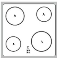
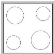
Type of hob
The oven is combined with a hob that can be made up of two types of heating elements: cast-iron electric plates (see diagram 1) or glass ceramic hobs (see diagram 2).
natural_image
Four empty circles arranged in a 2x2 grid within a square frame (no text or symbols)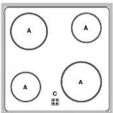
text_image
A A A A CSwitching on the glass ceramic hob
Traditional cooking zones
Traditional cooking zones are made up of circular heating elements. They turn red approximately ten seconds after they have been turned on.
Each cooking zone is fitted with a control knob allowing you to select from 6 different temperature settings from a minimum of 1 to a maximum of 6.
Residual heat indicator lights\*
The indicator lights (C) indicate that the temperature of the corresponding cooking zones have exceeded 60^ C, even after the heating element has been switched off.
Recommended power levels for various types of cooking:
| Setting | Normal or Fast Plate |
| 0 | Off |
| 1 | Cooking vegetables, fish |
| 2 | Cooking potatoes (using steam) soups, chickpeas, beans. |
| 3 | Continuing the cooking of large quantities of food, minestrone |
| 4 | For roasting (average) |
| 5 | For roasting (above average) |
| 6 | For browning and reaching a boil in a short time. |
Practical advice on using the glass ceramic hob
! The glue that is applied on the gaskets leaves some traces of grease on the glass. Before using the appliance, we recommend you eliminate these with a special non-abrasive cleaning product. During the first few hours of use there may be a smell of rubber which will disappear very quickly.
To obtain the best results with your hob:
- Use flat-bottomed pans to ensure that they adhere to the cooking zone perfectly.
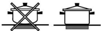
natural_image
Two cooking pots with crossed x-metty lines, no text or symbols present- Always use pans with a diameter that is large enough to cover the hotplate fully, in order to use all the available heat.

natural_image
Three diagrams showing crossed-out electrical symbols on a surface, no text or labels present- Make sure that the bottom of the cookware is always dry and clean to guarantee correct adherence and long life, not only for the cooking zones but also for the cookware itself.
- Avoid using the same cookware that is used on gas burners: the heat concentration on gas burners may deform the base of the pan, causing it not to adhere correctly.
- Never leave a cooking zone on without cookware on it because as it heats up and rapidly reaches the maximum level, it could damage the heating elements.
! The appliance was designed and manufactured in compliance with international safety standards. The following warnings are provided for safety reasons and must be read carefully.
General safety
- The appliance was designed for domestic use inside the home and is not intended for commercial or industrial use.
- The appliance must not be installed outdoors, even in covered areas. It is extremely dangerous to leave the appliance exposed to rain and storms.
- When handling the appliance, always use the handles provided on the sides of the oven.
- Do not touch the appliance with bare feet or with wet or moist hands and feet.
- The appliance must be used to cook food by adults only and according to the instructions in this manual.
- Do not touch the heating elements and parts of the oven door when the appliance is in use; these parts become extremely hot. Keep children well away from the appliance.
- Ensure that the power supply cable of other electrical appliances does not come into contact with the hot parts of the oven.
- The openings used for ventilation and dispersion of heat must never be covered.
- Always grip the oven door handle in the centre: the ends may be hot.
- Always use oven gloves to place cookware in the oven or when removing it.
- Do not use aluminium foil to line the bottom of the oven.
- Do not place flammable materials in the oven: if the appliance is switched on by mistake, it could catch fire.
- Always make sure the knobs are in the “●”/“O” position when the appliance is not in use.
- When unplugging the appliance always pull the plug from the mains socket, do not pull on the cable.
- Never carry out any cleaning or maintenance work without having unplugged the plug from the mains.
- In the case of a malfunction, under no circumstances should you attempt to repair the appliance yourself. Repairs carried out by inexperienced persons may cause injury or further malfunctioning of the appliance. Contact a Service Centre (see Assistance).
- Do not rest heavy objects on the open oven door.
- The glass ceramic hob is resistant to mechanical shocks, but it may crack (or even break) if hit with a sharp object
such as a tool. If this happens, disconnect the appliance from the electricity mains immediately and contact a Service Centre.
- Remember that the temperature of the cooking zones remains relatively high for at least thirty minutes after they have been switched off.
- Keep any object that could melt away from the hob, for example plastic and aluminium objects, or products with a high sugar content. Keep plastic or aluminium objects away from the hob: if you forget them on surfaces that are still hot, they may cause serious damage to the hob.
- The appliance should not be operated by people (including children) with reduced physical, sensory or mental capacities, by inexperienced individuals or by anyone who is not familiar with the product. These individuals should, at the very least, be supervised by someone who assumes responsibility for their safety or receive preliminary instructions relating to the operation of the appliance.
- Do not let children play with the appliance.
Disposal
- Observe local environmental standards when disposing packaging material for recycling purposes. Observe existing legislation when disposing of the old appliance.
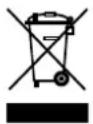
- The European Directive 2002/96/EC on Waste Electrical and Electronic Equipment (WEEE), requires that old household electrical appliances must not be disposed of in the normal unsorted municipal waste stream. Old appliances must be collected separately in order to optimise the recovery and recycling of the materials they contain and reduce the impact on human health and the environment. The crossed out “wheeled bin” symbol on the product reminds you of your obligation, that when you dispose of the appliance it must be separately collected. Consumers should contact their local authority or retailer for information concerning the correct disposal of their old appliance.
Respecting and conserving the environment
- By using the appliance in the hours between late afternoon and early morning, you can help reduce the work load placed on electrical companies.
- Always keep the oven door closed when using the GRILL mode to attain best results and to save energy (approximately 10% ).
- Regularly check the door seals and wipe clean to ensure they are free of debris so that they stick properly to the door and do not allow heat to disperse.
Switching the appliance off
Disconnect your appliance from the electricity supply before carrying out any work on it.
Cleaning the appliance
- The stainless-steel or enamel-coated external parts as well as the rubber seals may be cleaned using a sponge that has been soaked in lukewarm water and neutral soap. If these stains are difficult to remove, use only specialised products. After cleaning, rinse and dry thoroughly. Do not use abrasive powders or corrosive substances.
- Ideally, the inside of the oven should be cleaned after each use, when it is still lukewarm. Use hot water and detergent, rinse and dry with a soft cloth. Do not use abrasive products.
- The accessories can be washed like everyday crockery (even in your dishwasher).
! Never use steam cleaners or pressure cleaners on the appliance.
Cleaning the oven door
Clean the glass part of the oven door using a sponge and a non-abrasive cleaning product, then dry thoroughly with a soft cloth. Do not use rough abrasive material or sharp metal scrapers as these could scratch the surface and cause the glass to crack. To clean more thoroughly, you can remove the oven door.
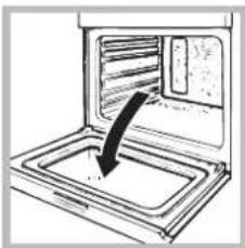
natural_image
Diagram of a microwave oven with a black arrow indicating airflow direction (no text or symbols)- Open the oven door fully (see diagram).
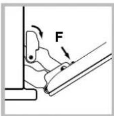
text_image
F- lift up and turn the small levers situated on the two hinges; (see diagram).
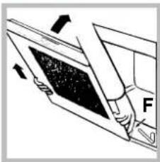
natural_image
Diagram of a mechanical component with force arrows indicating direction (no text or symbols)- Grip the door on the two external sides and close it approximately half way. Unlock the door by pressing on the clamps F, then pull the door towards you lifting it out of its seat (see diagram).
To replace the door, reverse this sequence.
Inspecting the seals
Check the door seals around the oven periodically. If the seals are damaged, please contact your nearest After-sales Service Centre (see Assistance). We recommend not using the oven until the seals have been replaced.
Replacing the light bulb
To replace the oven light bulb:
natural_image
Pure technical diagram showing two circular components with a curved arrow indicating direction, no text or symbols present.- Remove the glass cover of the lamp-holder.
- Remove the light bulb and replace it with a similar one: Wattage 25 W, cap E 14.
- Replace the glass cover (see diagram).
Assistance
Communicating:
- appliance model (Mod.)
- serial number (S/N)
This information is found on the data plate located on the appliance and/or on the packaging.


Français, 12
Nederlands, 23English, 1
Sommaire
Installation, 13-15
Positionnement
natural_image
Technical line drawing of a structural support frame with two horizontal bars and dashed lines indicating hidden edges (no text or symbols)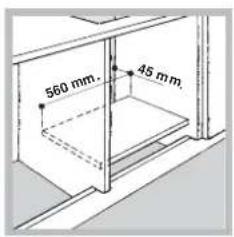
text_image
560 mm. 45 mm.natural_image
3D rendered mechanical component with cutouts and mounting holes (no text or symbols)natural_image
3D rendered mechanical component with black and gray sections (no text or symbols)natural_image
3D rendered mechanical component with black and gray sections (no text or symbols)natural_image
Diagram showing a device with a screwdriver inserted into a housing, enclosed in a circular arrow indicating rotation (no text or symbols present)text_image
N L 1 L 5 3 4 2400V 3N\~H05RR-F 5x2.5 CEI-UNEL 35363 3 L 2
text_image
N L1 P L2 L3text_image
N L S1 S2 P N230V \~H05RR-F 3x4 CEI-UNEL 35363
text_image
≡ N L 1 L 6 3 1 4 2400V 2N\~H05RR-F 4x4 CEI-UNEL 35363 2
natural_image
Four empty circles arranged in a 2x2 grid within a square frame (no text or symbols)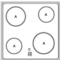
text_image
A A A A Cnatural_image
Two identical cooking pots with crossed x-bracing, no text or symbols presentnatural_image
Three diagrams showing crossed-out electrical symbols on a surface, no text or labels presentnatural_image
Diagram of a microwave oven with a black arrow pointing to the interior (no text or symbols)text_image
Diagram showing a mechanical or electrical component with labeled force F and directional arrows indicating movement or force direction.natural_image
Diagram of a person using a tablet device to interact with a screen (no text or symbols visible)natural_image
Diagram showing airflow around a circular object with directional arrows, no text or symbols presentnatural_image
Pure technical line drawing of a cabinet or enclosure structure without any text, numbers, or symbols
text_image
560 mm. 45 mm.Centreren en bevestigen
natural_image
3D rendered mechanical part with cutouts and mounting holes (no text or symbols)natural_image
3D rendering of a mechanical component with black and gray sections (no text or symbols visible)natural_image
3D rendered mechanical component with black and gray sections (no text or symbols)natural_image
Diagram showing a screwdriver inserted into a device component, with arrows indicating direction (no text or symbols present)text_image
N L 1 L 5 3 1 4 2400V 3N\~H05RR-F 5x2.5 CEI-UNEL 35363 3 L 2
text_image
N L1 P L2 L3natural_image
Four empty circles arranged in a 2x2 grid within a square frame (no text or symbols)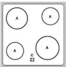
text_image
A A A A Cnatural_image
Two cooking pots with crossed x-bracing, one plain and one with a lid (no text or symbols)natural_image
Three diagrams showing crossed-out electrical symbols on a surface, no text or labels presentnatural_image
Line drawing of an oven with a black arrow pointing to the interior (no text or symbols)text_image
Diagram showing a mechanical or electrical component with labeled force F and directional arrows indicating movement or force direction.natural_image
Diagram of a mechanical component with force arrows indicating direction (no text or symbols)natural_image
Diagram showing two circular components with directional arrows, no text or symbols presentnatural_image
Pure technical line drawing of a structural frame with no text, numbers, or symbols
text_image
560 mm. 45 mmnatural_image
3D rendered mechanical part with cutouts and mounting holes (no text or symbols)natural_image
3D rendered mechanical component with black and gray sections (no text or symbols)natural_image
3D rendered mechanical component with black and gray sections (no text or symbols)natural_image
Diagram showing a screwdriver inserted into a device component, with arrows indicating direction (no text or symbols present)text_image
N L 1 L 5 3 4 2400V 2N\~H05RR-F 4x4 CEI-UNEL 35363 2
natural_image
Four empty circles arranged in a 2x2 grid within a square frame (no text or symbols)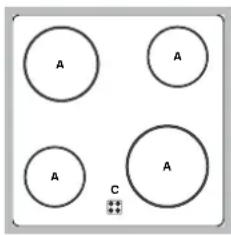
text_image
A A A A Cnatural_image
Diagram of a kitchen oven with a tray and vent, showing a black arrow pointing to the interior (no text or symbols)natural_image
Diagram of a person using a tablet device to interact with a screen, showing directional arrows (no text or symbols)natural_image
Diagram showing two circular components with curved arrows indicating motion or rotation, no text or symbols presentnatural_image
Pure technical line drawing of a structural component without any text, numbers, or symbols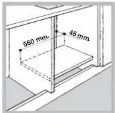
text_image
560 mm 45 mmnatural_image
3D rendered mechanical part with cutouts and mounting holes (no text or symbols)natural_image
3D rendered mechanical component with black and gray sections (no text or symbols)natural_image
3D rendering of a black and gray mechanical component with a cylindrical protrusion (no text or symbols visible)natural_image
Diagram showing a screwdriver inserted into a device component, with arrows indicating direction (no text or symbols present)text_image
± N L 1 L 5 3 1 4 2400V 2N\~H05RR-F 4x2.5 CEI-UNEL 35363
natural_image
Four empty circles arranged in a 2x2 grid within a square frame (no text or symbols)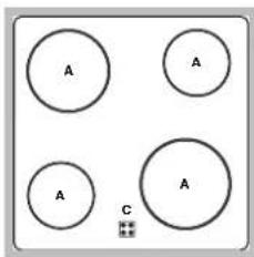
text_image
A A A A Cnatural_image
Two cooking pots with crossed x-marks, one plain and one with a lid, placed on a surface (no text or symbols)natural_image
Three diagrams showing crossed-out electrical symbols on a surface, no text or labels presentnatural_image
Diagram of a microwave oven with a tray and vent, showing airflow direction (no text or symbols)natural_image
Diagram of a person using a tool to lift a panel, with arrows indicating force direction (no text or symbols)natural_image
Diagram showing two circular components with directional arrows, no text or symbols presentnatural_image
Technical line drawing of a structural frame with horizontal supports and dashed lines indicating hidden edges (no text or symbols)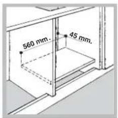
text_image
560 mm. 45 mm.Centrado y fijación
natural_image
3D rendered mechanical part with cutouts and mounting holes (no text or symbols)natural_image
3D rendering of a mechanical component with black and gray sections (no text or symbols)natural_image
3D rendered mechanical component with black and gray sections (no text or symbols)natural_image
Diagram showing a screwdriver inserted into a device component, with arrows indicating direction (no text or symbols present)text_image
N L 1 L 5 3 4 2400V 3N\~H05RR-F 5x2.5 CEI-UNEL 35363 3 L 2
text_image
N L1 L2 L3 Ptext_image
N L 1 L 5 3 4 2400V 2N\~H05RR-F 4x4 CEI-UNEL 35363 2
natural_image
Four empty circles arranged in a 2x2 grid within a square frame (no text or symbols)