Wave Pro 1909 - Bike BH FITNESS - Free user manual and instructions
Find the device manual for free Wave Pro 1909 BH FITNESS in PDF.
| Brand | BH Fitness |
| Model | Wave Pro 1909 |
| Product type | City bike / all-road bike |
| Safety standard | EN 14764 (city), EN 14766 (MTB), EN 14781 (racing), EN 15194 (e-bike) |
| Maximum authorized weight (bike + cyclist + luggage) | 155 kg (city, MTB, racing), 165 kg (e-bike) |
| Brakes | V-brake or Cantilever |
| Drivetrain | Front and rear derailleur, multiple gears |
| Suspension | Yes (adjustable, SAG between 15% and 35%) |
| Adjustments | Saddle height, handlebar height, stem (traditional or Ahead), brake position |
| Tires | Pressure indicated on sidewall, replace according to wear |
| Routine maintenance | Cleaning with soapy water, chain lubrication (SAE-20), check brakes and tightenings before each use |
| Cleaning | Damp sponge and mild detergent, no high-pressure or steam cleaner |
| Wear parts | Tires, inner tubes, brake pads, disc brake pads, rims, chain, bulbs, batteries |
| Tightening torques | M4: 0.3-0.4 daN·m ; M5: 0.6-0.8 ; M6: 1-1.4 ; M8: 2.5-3.8 ; M10: 4.9-7.3 |
| Intended use | Public roads, path, MTB, racing (according to standard) |
| Recommended accessories | Approved helmet, regulatory lighting |
Frequently Asked Questions - Wave Pro 1909 BH FITNESS
User questions about Wave Pro 1909 BH FITNESS
0 question about this device. Answer the ones you know or ask your own.
Ask a new question about this device
Download the instructions for your Bike in PDF format for free! Find your manual Wave Pro 1909 - BH FITNESS and take your electronic device back in hand. On this page are published all the documents necessary for the use of your device. Wave Pro 1909 by BH FITNESS.
USER MANUAL Wave Pro 1909 BH FITNESS
natural_image
Pure geometric lines and markers without any text, numbers, or symbolsÍNDICE
Español 2
Française 16
English 30
Portugues 43
Deustch 57
Italiano 71
Ελληνικά 85


INTRODUCCIÓN
natural_image
Mechanical diagram showing a wheel and gear assembly with a labeled component (A), no text or symbols present.natural_image
Mechanical diagram showing a gear mechanism with a rotating wheel and a separate mechanical component (no text or symbols)natural_image
Diagram of a mechanical device with a lever and handle, showing no text or symbolsnatural_image
Gray triangular play button icon with white letter 'E' on side (no additional text or symbols)
text_image
Technical diagram showing mechanical components labeled A and B with rotating arrows and assembly partsnatural_image
Gray triangular play button with white letter F (no text or symbols beyond the letter)
text_image
Minimum 39 mm. A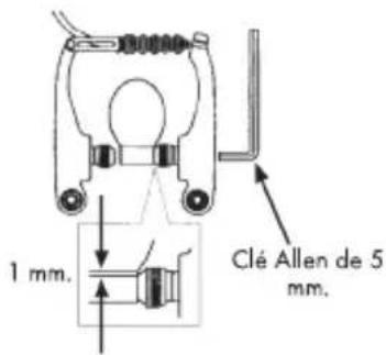
text_image
1 mm. Clé Allen de 5 mm.text_image
Diagram showing three stages of layered structure with arrows indicating progression from top to bottom layersThanks and congratulations for acquiring a BH bicycle, a quality product sprung from a great experience of more than one hundred years. Your bicycle is the fruit of a lot of research, the selection of first-class components and strict in-house and external testing. All this guarantees its high reliability even in extreme conditions of use. We wish you to enjoy your bicycle for many years.
SCOPE OF THIS HANDBOOK
This handbook is intended to provide you with basic instructions for an easier adjustment and maintenance of your bicycle. Please read it carefully before riding your bicycle and follow these instructions in order to obtain optimum performances and long life expectancy from your bicycle. If you purchased a bicycle featuring specific components whose setting and operating instructions are not included in this handbook, then refer to the instructions of those components' manufacturer, which accompany your bicycle.
Pay special attention to the instructions preceded by one of the following symbols:
 | This symbol means that failure to comply with the instructions rigorously or to carry out the specified operations may put your personal safety or your life at risk. |
 | This symbol refers to information that requires special attention, such as settings and periodical maintenance. |
 | When you see this symbol, consult the specific instruction manual of the component's manufacturer to avoid damage to your bicycle or to the environment. |
RESPONSIBILITY
If in doubt about any of the processes described in this handbook, please contact your local BH dealer. Failing to comply with these instructions is the bicycle owner's responsibility. We would recommend that you should entrust your dealer with the maintenance of your bicycle.
SAFETY
If you are going to ride your bicycle on a public road, you need to have it fitted with the lighting and warning signals required by your local traffic regulations.
For your personal safety's sake, BH recommends that you should wear a certified crash helmet wherever you ride and whatever the bicycle conditions of use may be.
The bicycle has a sticker with the following data:
A lettering saying: "Conforme aux exigences de sécurité"
The safety standard the bicycle is compliant with:
o City and trekking bicycles: EN 14764
o Bicycles for children: EN 14765
o Mountain bicycles: EN14766
o Racing bicycles: EN 14781
o Electrically power assisted bicycles: EN 15194
A lettering saying: "In compliance with safety requirements"
To identify the use your bicycle has been designed for, check the EN number on the a.m. sticker. Next, read the section relating to said EN carefully:
> EN 14764: City and trekking bicycles. Safety requirements and test methods.
This European Standard specifies safety and performance requirements for the design, assembly, and testing of bicycles and sub-assemblies intended for use on public roads, and lays down guidelines for instructions on the use and care of such bicycles.
It applies to bicycles that have a maximum saddle height of 635 mm or more and that are intended for use on public roads.
It does not apply to mountain bicycles and racing bicycles, tradesman's delivery bicycles, recumbent bicycles, tandems and bicycles designed and equipped for use in sanctioned competitive events.
> EN 14765: Bicycles for young children. Safety requirements and test methods.
This European Standard specifies safety and performance requirements for the design, assembly, and testing of bicycles and sub-assemblies intended for use by young children. It also lays down guidelines for instructions on the use and care of such bicycles.
It applies to bicycles with a maximum saddle height of more than 435 mm and less than 635 mm (typical rider weight of 30 kg), and propelled by a transmitted drive to the rear wheel.
It does not apply to special bicycles intended for stunting.
> EN 14766: Mountain bicycles. Safety requirements and test methods.
This European Standard specifies safety and performance requirements for the design, assembly, and testing of bicycles and sub-assemblies intended for off-road, rough-terrain use, and lays down guidelines for instructions on the use and care of such bicycles.
It applies to bicycles on which the saddle is adjustable to provide a maximum saddle height of 635 mm or more.
It does not apply to racing bicycles and specialised types of bicycle such as tandems or bicycles designed and equipped for use in severe applications such as sanctioned competition events, stunting, or aerobatic manoeuvres.
> EN 14781: Racing bicycles. Safety requirements and test methods.
This European Standard specifies safety and performance
requirements for the design, assembly and testing of racing bicycles and sub-assemblies, and lays down guidelines for instructions on the use and care of such bicycles.
It applies to racing bicycles intended for high-speed amateur use on public roads, and on which the saddle is adjustable to provide a maximum saddle height of 635 mm or more.
It does not apply to mountain bicycles, nor to specialised types of racing bicycle such as tandems or bicycles designed and equipped for use in sanctioned competitive events.
> EN 15194: Cycles – Electrically power assisted cycles – EPAC Bicycles.
This European Standard is intended to cover electrically power assisted cycles of a type which have a maximum continuous rated power of 0.25kW, of which the output is progressively reduced and finally cut off as the vehicle reaches a speed of 25 Km/h, or sooner, if the cyclist stops pedalling.
This European Standard specifies safety requirements and test methods for the assessment of the design and assembly of electrically power assisted bicycles and sub-assemblies for systems using battery voltage up to 48 VDC or integrated a battery charger with a 230 V input.
This European Standard specifies requirements and test methods for engine power management systems, electrical circuits including the charging system for the assessment of the design and assembly of electrically power assisted cycles and sub-assemblies for systems having a voltage up to and including 48 VDC or integrated a battery charger with a 230 V input.

Warning! Using your bicycle for any other than its design purpose
may lead to severe injuries, and even death. If you have purchased a children's bicycle, make sure you will teach your child to use the bicycle correctly, and more particularly the brakes.

Warning! Except in some countries such as the United Kingdom,
the brake lever on the left-hand side of the handlebar works the front brake and the brake lever on the right-hand side of the handlebar works the rear brake. Before using your bicycle for the first time, check which brake lever works upon which brake.

Caution! Like all mechanical items, a bicycle supports high stresses
and wears out. The different constructional materials and components may react differently to wear and tear or to fatigue. After reaching its anticipated service life, any component may break suddenly, causing serious injuries to the cyclist. Cracks, scratches and discolorations in highly stressed areas are signs that a component has exceeded its useful life and need replacement
Maximum Permissible Weights Table
| TYPE OF BICYCLE | MAXIMUM AUTHORISED WEIGHT(bicycle + rider + luggage) | MAXIMUM WEIGHT OF LUGGAGE |
| City bikes | 155 kg (341,7 lb) | Consult therecommendations for yourluggage rack accessories |
| Children's bikes withwheel size of:14" / 16" / 18"20" / 24" | 65 kg (143,3 lb)95 kg (209,4 lb) | |
| Mountain bikes | 155 kg (341 lb) | |
| Racing bikes | 155 kg (341 lb) | |
| Folding bikes | 145 kg (319,6 lb) | |
| Pedal-assisted bikes | 165 kg (363,7 lb) |
DIRECTIONS FOR USE

Before using your bicycle, check the brakes for proper operation and verify that the wheel quick release system or fixing nuts are tightly secured. Also make sure the tyre pressure is adequate and that the seat pillar, seat and handlebar stem are correctly adjusted and tight. Check that all fasteners in general are tight. For further information, refer to the sections concerned.
• Periodic maintenance

Your bicycle requires regular maintenance and minimum overhauls. The frequency of these will depend on the bicycle type (roadster, touring, MTB) as well as on the frequency and conditions of use.
| FREQUENCY | CHECK PONITS | SCOPE OF MAINTENANCE | ||
| Inspection | Cleaning | Lubrication | ||
| Before each use | Quick release / wheel fixing nuts torqueFront and rear brakeTyres: wear and pressureOperation of the lighting systemTightness of handlebar stem and seat pillarTorque of fasteners in general | |||
| Every 500km. | Tightness of steering systemTorque of pedals and cranksSpoke tension | |||
| Every month | ChainGearsFree wheel | SAE-20SAE-20SAE-20 | ||
| Every 6 months | Pedal pinsWheel hubsSeat pillarSteering system | |||
| Heavy grease | ||||
| Every year | Broke cables and gears | CHANGE | ||

IMPORTANT WARNING: We strongly recommend that
maintenance and overhauls be carried out by your dealer. Above frequencies are given for guidance only and apply to normal conditions of use. Mountain bike maintenance intervals should be shorter, in consideration of their intensive use.
• Preparing the bicycle for riding
Setting of the seat height
This value is calculated by multiplying the inside leg, as measured with the shoeware to be worn when riding the bicycle, by coefficient 0.885. The product is the distance from the centre of the saddle to the centreline of the bottom bracket axle screw. To adjust the seat height, release the seat pin, move the seat pillar as necessary, retighten the seat pin.

IMPORTANT WARNING: For your safety, the reference mark on the
seat pillar (horizontal mark indicating the maximum permissible adjustment of the seat) should never be above the top edge of the seat tube.

Setting of the handlebar height
For a comfortable position on the bicycle, that would induce neither neck pain nor backache, we recommend the use of the settings tabulated below.
| Seat height | Offset with handlebar height |
| 65/68 cm | 5/6 cm |
| 69/72 cm | 6/7 cm |
| 73/76 cm | 7/8 cm |
| 77/79 cm | 8/9 cm |
| 80/82 cm | 9/10 cm |

IMPORTANT WARNING: For traditional stems, the manufacturer-
specified height shall by no means be exceeded.
• Suspension setting (SAG)
General definition of SAG: In the simple case of a helical spring, SAG is the ratio of the spring deformation under a given load to the no-load spring length.
For the case under consideration (suspension bicycles), SAG is the ratio of:
-
The vertical movement of the bottom bracket axle due to the rider weight in rider's usual position on the bicycle, with the fork, frame and shock absorber in any position;
-
The maximum vertical movement of the bottom bracket axle that the fork, frame and shock absorber permit.
For your guidance, correct SAG values range from 15% to 35%.

To determine the correct SAG value, refer to the specific suspension and frame shock absorber instructions supplied with the bicycle.
• Tightening torques for bolted joints

On assembling any parts, always use the appropriate wrenches and no more than the required hand driving force. Bolts and/or nuts must be placed if their threads are found damaged when screwing them on or e following table shows the tightening torques for various screw sizes, otherwise expressly stated.
• Testing the braking distance
Before getting on your bike, check both front and rear brakes for perfect condition. Any cable worn out must be replaced immediately.
It is recommended that both brakes are applied simultaneously, in order to prevent falls, above all on humid roadways.
The braking distance on a wet surface is approximately 40% longer than on a dry one.

WARNING! The use of streamlining extensions or accessories
attached to the handlebars may negatively affect the response time on braking or turning.
- Cleaning
To keep your bicycle in good conditions, take the following elementary precautions:
o Remove dust and mud with a wet sponge and a soft detergent. Do not use solvents or very alkaline detergents when cleaning painted parts.
o Plastic components should be cleaned only with soapy water.
GB
o Tyres may be cleaned with a sponge or a brush and soapy water.
o Dry up the bicycle with a cloth or chamois.
o Lubricate the chain drive, after each cleaning process.

IMPORTANT NOTE: The use of high-pressure cleaners should be
avoided. Under no circumstances shall a steam jet be used.
BASIC SETTINGS
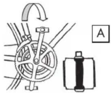
• Fitting of pedals
natural_image
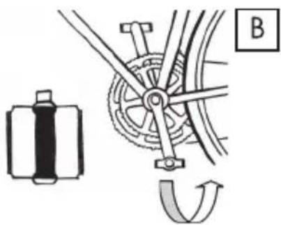
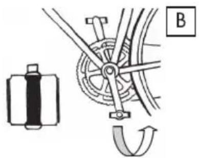
Mechanical diagram showing a wheel and gear assembly with no visible text or symbolsRHS pedal: The RHS pedal is identified by letter R marked on its pin. For mounting the pedal, screw on the pin clockwise (Fig. A).
natural_image
Mechanical diagram showing a gear assembly and rotational motion (no text or symbols)LHS pedal: The LHS pedal is identified by letter L marked on its pin. For mounting the pedal, screw on the pin anticlockwise (Fig. B).
• Setting of handlebar stem
text_image
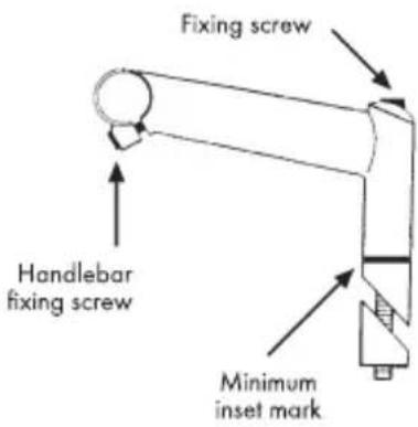
Fixing screw Handlebar fixing screw Minimum inset markConventional stem: Back off the stem fixing screw. Tap softly to unblock the taper ring. Adjust to the desired height. Retighten the stem fixing screw.

IMPORTANT WARNING:
Check that the minimum inset mark is not visible.
Adjusting the handlebar position: Release the handlebar fixing screw. Turn the handlebar to the desired angle. Retighten the fixing screw.

text_image
Stem cover Clamping screwsAhead stem: To adjust height, remove the cap and stem, by loosening the fixing screw and pinch bolts. Next, insert spacers under or above the stem as required. Retighten the stem cap first, until the steering column turns adequately. Finally, tighten the pinch bolts.

IMPORTANT WARNING:
The distance from the top of the stem or upper spacer to the top of the steerer must be between 2 and 4mm.
• Removing and fitting wheels
Removing: Loosen the brake caliper by releasing or slackening the brake cable. Pull the release lever from position A to position B. Manually back off the adjusting nut. Remove the wheel.
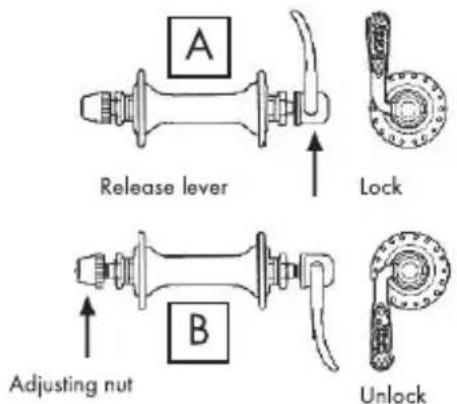
text_image
A Release lever Lock B Adjusting nut UnlockFitting: Insert the wheel axle deep into the slot of the fork end (front wheel) or of the frame (rear wheel), with the release lever in the 'unlock' position. Tighten the adjusting nut slightly. Put the release lever in position A.

IMPORTANT NOTE: Locking the lever requires a significant manual
force. Otherwise, tighten the nut further. If the lever moves with a minimum manual force, it is not tight enough. Drive the adjusting nut tighter.
- Seat height
natural_image
Diagram of a mechanical lever mechanism with no visible text or symbolsMinimum inset mark
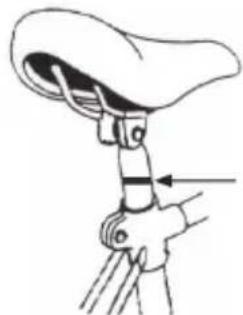
Adjusting the seat height: Introduce the seat pillar in the seat tube. When the seat is at the desired height, tighten the seat pin or fixing screw.

IMPORTANT NOTE: The minimum inset mark should never be, if there is to be a minimum safety length of the seat pillar in the seat
• Installing stabilisers
For perfect service, this safety device requires adequate fitting and setting.

FITTING: Various stabiliser-mounting systems are available. They must be fixed to the rear of the bicycle (to the rear hub or frame). Refer to specific instruction manual supplied with the bicycle.
SETTING: With a view to improving the bicycle stability in turns, adjust the installed stabilisers in such a way that the stabiliser wheels clear the ground by 1 cm to 2.5 cm when the bicycle is in its vertical position.
MAINTENANCE
• V-brake
Setting: While pressing the V-brakes against the rim, adjust the brake shoe by changing washer B (3mm or 6 mm) so that distance A is not less than 39 mm.
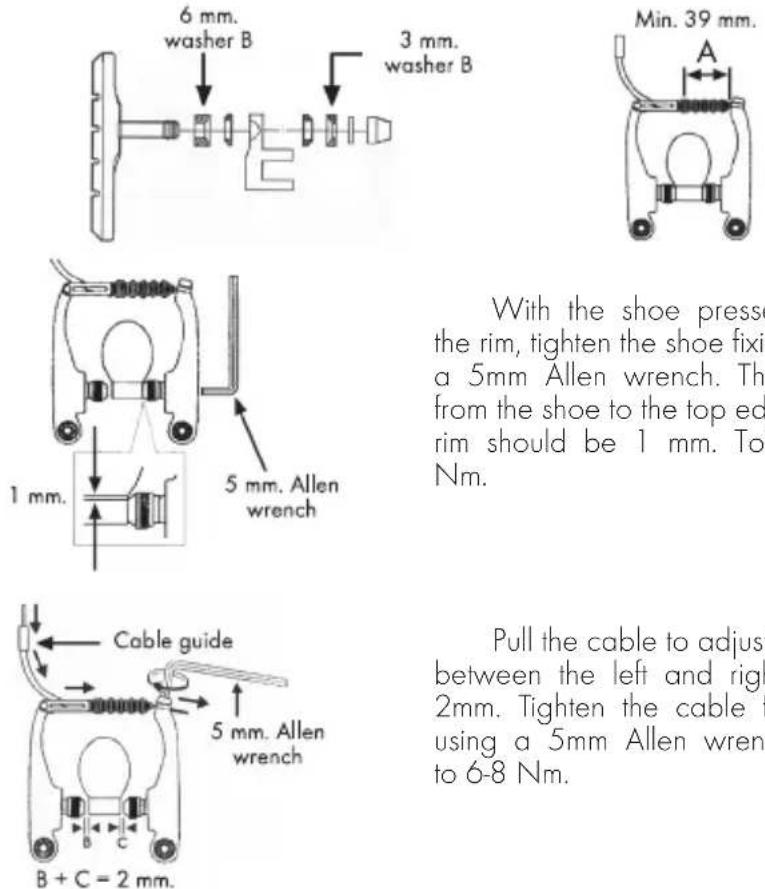
With the shoe pressed against the rim, tighten the shoe fixing nut with a 5mm Allen wrench. The distance from the shoe to the top edge of the rim should be 1 mm. Torque to 6-8 Nm.
Pull the cable to adjust the gap between the left and right shoes to 2mm. Tighten the cable fixing bolt using a 5mm Allen wrench. Torque to 6-8 Nm.
Finally adjust the balance, with the spring tension adjusting screws, in such a way that each shoe clears the rim by 1 mm.
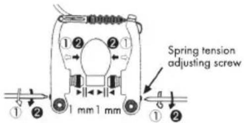
text_image
Spring tension adjusting screw 1 mm 1 mm- Cantilever brake
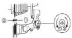
Setting: Release the shoe fastener. Pull the cable taut, bringing the transverse cable in line with the yoke. Lock the main cable at the back the yoke. Adjust the balance by means of the spring tension adjusting screws.
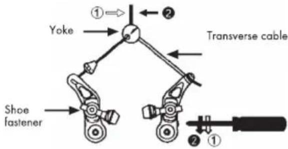
text_image
Yoke ① ② Transverse cable Shoe fastener ② ①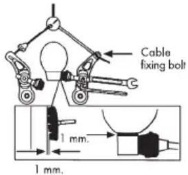
text_image
Cable fixing bolt 1 mm. 1 mm.Apply the brake shoes onto the rim and adjust the height until the bolt is perpendicular to the rim. Move the shoes 1mm back and secure them. Undo the cable fixing bolt and slacken the cable 2mm to obtain a 1mm gap between the rim and the shoe.
text_image
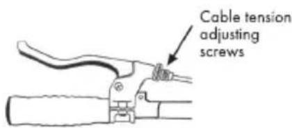
Cable tension adjusting screwsIf the balance requires finer adjustment, turn the cable tension adjusting screws (barrel) at the brake lever.
Check that the bottom of the external plate of the cage clears the top of the big chainwheel teeth by 1 to 3 mm.
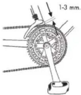
text_image
1-3 mm.Low gear stop adjustment:
With the chain over the smallest chainwheel and largest sprocket, turn the low gear stop screw until the distance between the chain and the inside plate of the cage is 1 to 3mm
High gear stop adjustment: With the chain over the largest chainwheel and smallest sprocket, turn the high gear stop screw until the distance between the chain and the outside plate of the cage is 1 to 3mm.
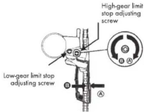
text_image
High-gear limit stop adjusting screw Low-gear limit stop adjusting screw B A AIndexing adjustment: With the chain over the middle chainwheel, turn the cable tension adjusting screw (adjusting barrel) clockwise if the chain touches the inside plate of the cage or counterclockwise if the chain is in contact with the outside plate of the cage.
Low limit adjustment
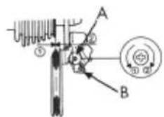
text_image
Technical diagram showing mechanical assembly with labeled components A and B, and numbered parts ① and ②.High limit adjustment
High and low limit stop adjustment: This is done with screws A and B. Turn the two screws in order that the chain will not jump off. The shift roller will be in line with the smallest and largest sprockets.
Indexing adjustment: Move the shifter to the second click. Turn the cable tension adjusting screw (barrel) till you get a perfect match on the second sprocket.
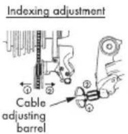
text_image
Indexing adjustment Cable adjusting barrel- Shifting
text_image
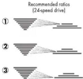
Recommended ratios (24-speed drive) ① ② ③For better results and in order to prevent damage to the drive system, it is recommended that you should not stress the pedals when shifting. So, avoid shifting when making an effort or riding uphill.
Do not use extreme ratios: smaller chainwheel linked to either of the two smallest sprockets; larger chainwheel linked to any of the two largest sprockets; central chainwheel linked to either the largest or the smallest sprocket. These settings may cause both a lateral distortion of the chain that will impair the proper operation of the shifter and premature wear of the drive components.
To improve performance when changing gears, follow the following recommendations:
- When going uphill, use the gear combinations shown in Figure 1.
- When going up gentle slopes, or on the flat, use the gear combinations shown in figure 2.
- When descending, use the gear combinations shown in figure 3.
- Tyre pressure
Tyre pressure shall be as indicated on the tyre outside. Pressures are stated in PSI or bar, with the maximum permissible value shown. Mind that 14 psi are equal to 1 bar and 1 bar = 1 kg/cm2. Underinflated tyres are more subject to pinch flats (or "snakebites") and may cause damage to the rim. Excessive tyre pressure may reduce the tread's ground adhesion.
Always change the tires when they reach their wear limit. A good tread is essential to a comfortable ride and safe braking.
- Replacement parts
To keep your bicycle in the best possible working condition and for your safety, it is very important to only use original spare parts.
• Replacement of wear parts
The usual wear parts are tires, inner tubes, brake pads, discs and shoes, and the rims when they are part of the braking system, Light bulbs, batteries and their installation.

Tires: Change them for identical or equivalent ones. See the mark on tside of the tire (Norm E.T.RTO).
Please note that if the outside diameter of the replacement tire is greater than the original tire size, you may touch the front wheel or mudguard with the tip of your feet when turning. As a result, you may lose control of the bicycle and be seriously injured. The same may happen if you change the crankset for longer ones.

Tubulars: For a perfect fit on the rims, tubulars must be inflated to tain minimum pressure. Check the recommended pressures in the tion manuals of the rim and tubular manufacturer. Also, mind the bly methods the manufacturer recommends.
Inner tubes: replace with an equivalent type of inner tube that is compatible with the tyre. The make can be found on the outside of the inner tube (E.T.R.T.O. Standard).

Brake shoes: Check brake shoe wear periodically. When the all grooves are invisible, change the shoes for others of same type and sions.

Brake pads and discs: Refer to the manufacturer's specific manuals ed with the bicycle.

Rims: If the rims are part of the bicycle braking system (the shoes te on the rims) they can wear excessively. Check the control marks e rims regularly, and change the rims for others of same type and sions as and when necessary.
Light bulbs and their installation: Replace with an equivalent type of bulb. Refer to the markings on the metal part of the bulb.
Batteries: Replace with an equivalent type. Refer to the markings on the outside of the battery.
INTRODUÇÃO
natural_image
Mechanical diagram showing a wheel and gear assembly with no visible text or symbolsnatural_image
Mechanical diagram showing a gear mechanism and rotational motion (no text or symbols)natural_image
Gray triangular play button icon with white letter 'P' on side (no text or symbols beyond the icon)
ZWECK DIESES HANDBUCHES
natural_image
Mechanical diagram showing a wheel and gear assembly with no visible text or symbolsnatural_image
Gray triangular play button icon with white letter D (no text or symbols beyond the icon)
Gebrauchsanweisung
natural_image
Mechanical diagram showing a gear mechanism and a battery component, with no visible text or symbols.natural_image
Diagram of a hand holding a lever with a curved blade and directional arrow (no text or symbols)text_image
Mind. 39 mm. A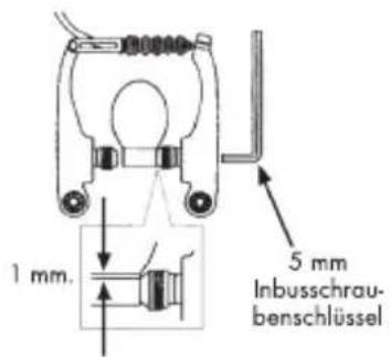
text_image
1 mm. 5 mm Inbusschraubenschlüsseltext_image
Technical diagram showing mechanical assembly with labeled components A and B, including a circular component with cross-sectional view.text_image
Technical diagram showing mechanical components labeled A and B with rotational arrows indicating motion or force directions.text_image
Diagram showing three stages of layered structure transformation with numbered labelstext_image
Technical diagram showing mechanical components labeled A and B with rotational arrows indicating motion or force directions.natural_image
Pure mechanical diagram of a shaft and housing assembly without any text or symbolsnatural_image
Diagram of a lever mechanism with a curved top and directional arrow (no text or symbols)bh@bhsa.es / www.BHbikes.com
BH FRANCE
BH FRANCE - T: 01 64 03 82 53
F: 01 64 03 83 82
NORD-OUEST - T: 06 80 68 36 88
info@sportlifebikes.gr
www.sportlifebikes.gr
natural_image
Pure geometric lines and markers without any text, numbers, or symbols
natural_image
Pure geometric lines and markers without any text, numbers, or symbols
natural_image
Pure geometric lines and markers without any text, numbers, or symbolsBH BIKES Europe, S.L.
C/ Perretagana, 10. Pol. Ind. Júndiz