ZIHAEK11000 - Mechanical chipper Zipper - Free user manual and instructions
Find the device manual for free ZIHAEK11000 Zipper in PDF.

| Product type | Shredder / Mechanical chipper |
| Brand and model | Zipper ZIHAEK11000 |
| Dimensions (L x W x H) | 1800 x 800 x 1150 mm |
| Net weight | 185 kg |
| Engine type | 4-stroke OHV, petrol |
| Maximum power | 9 kW |
| Displacement | 420 cm³ |
| Starting | Recoil and electric start (12 V battery) |
| Maximum branch diameter | 120 mm |
| Number of blades | 2 (drum and counter blade) |
| Blade speed | 2000 min⁻¹ |
| Guaranteed sound level (LWA) | 119 dB(A) |
| Recommended fuel | Unleaded petrol 95 RON |
| Engine oil | 15W40 |
| Accepted material types | Branches, hedges, shrubs, dry and wet garden waste |
| Main functions | Automatic shredding with feed hopper and adjustable discharge chute |
| Safety | Emergency stop, safety switch, projection protection |
| Routine maintenance | Checking oil level, cleaning air filter, belt adjustment, blade sharpening |
| Included accessories | Tow bar, trailer hitch |
| Warranty | 2 years (DIY use) / 1 year (professional use) |
Frequently Asked Questions - ZIHAEK11000 Zipper
User questions about ZIHAEK11000 Zipper
0 question about this device. Answer the ones you know or ask your own.
Ask a new question about this device
Download the instructions for your Mechanical chipper in PDF format for free! Find your manual ZIHAEK11000 - Zipper and take your electronic device back in hand. On this page are published all the documents necessary for the use of your device. ZIHAEK11000 by Zipper.
USER MANUAL ZIHAEK11000 Zipper
natural_image
Green industrial tiller with a red handle and 'ZIPPER ZI-HAEK4100' label (no additional text or symbols visible)
natural_image
Green agricultural machine labeled 'ZIPPER ZI-HAEK11000' with red handle, no visible text or symbols on the device itself.
ZI-HAEK4100 / ZI-HAEK11000
EAN: 9120039232690 / 9120039232683
C€
ATTENTION: Check Oil (15W40)!
11.1 Intended Use....25
11.2 Security instructions .... 26
11.3 Remaining risk factors....27
12 ASSEMBLY 28
12.1 Delivery content 28
12.2 Assembly 28
12.3 Checklist before each use 31
12.3.1 Checking the engine oil level 32
12.3.2 Checking the fuel tank level.... 32
13 OPERATION 33
13.1 Information on Initial Start-up....33
13.1.1 Test Run Initial Start-up.... 33
13.1.2 Notes on the first 20 operating hours.... 33
13.2 Operation instructions....33
13.3 Operation 34
13.3.1 Refuel, start, stop 34
Stopping the Macchine: 35
Emergency-stop: 35
Normal stop 35
14 MAINTENANCE 36
14.1 Maintenance plan 36
14.1.1 Cleaning the air filter 36
14.1.2 Cleaning the spark plug 36
14.1.3 Greasing of the blade drum 37
14.1.4 Adjusting the V-belt.... 37
14.1.5 Blades 37
14.1.6 Carburettor 37
14.1.7 Refuel 37
14.1.8 Cleaning 38
14.1.9 Storage.... 38
14.1.10 Disposal.... 38
15 TROUBLE SHOOTING 38
16 PREFACIO (ES) 39
17 SEGURIDAD 40
EN EC-CONFORM - This product complies with the EC-directives.
EN READ THE MANUAL! Read the user and maintenance manual carefully and get familiar with the controls in order to use the machine correctly and to avoid injuries and machine defects.
EN ATTENTION! Ignoring the safety signs and warnings applied on the machine as well as ignoring the security and operating instructions can cause serious injuries and even lead to death.
EN Protective clothing!
EN Do not grab into openings, in-feed chute or ejection chute during the running machine.
EN Don't touch rotating parts!
EN Warning about cut injuries!
EN Keep away unauthorized persons and pets.
EN Keep safety distance!
EN Warning against thrown-off items!
EN Stop the machine before any break and maintenance!
EN Warning of flammable liquids; turn off the engine before filling (gasoline
EN Danger of Intoxication (CO)! Only use outdoors and far from open windows and vents!
natural_image
Product catalog image showing five mechanical components: a pump, triangular fan, wheel rim, dual wheel, and curved bracket (no visible text or labels)ZI-HAEK11000:

natural_image
Product catalog image showing various automotive components including a robotic arm, triangular binoculars, tire wheel assembly, and mechanical clamp (no visible text or labels)6.2 Zusammenbau

HINWEI S
natural_image
3D mechanical component with labeled parts and arrows indicating assembly (no text or symbols)Standfuß:
natural_image
Close-up of mechanical components with wires and a labeled part 'd' (no readable text or symbols beyond the label)Achse:
natural_image
Two black-and-white photos showing a hand adjusting a metal bracket and a close-up of a mechanical component with circular features (no visible text or symbols)Standfuß:
natural_image
Close-up of a person adjusting a large tire with a hand holding the nut (no visible text or symbols)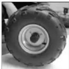
natural_image
Close-up of a small wheeled vehicle tire with visible tread pattern and central hub (no text or symbols)
natural_image
Close-up of a large tire with visible tread pattern and central hole (no text or symbols)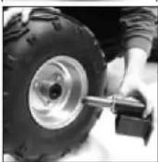
natural_image
Close-up of a person using a tire to lift a large off-road vehicle (no visible text or symbols)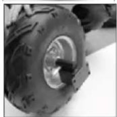
natural_image
Close-up of a tire with visible tread pattern and central disc (no text or symbols)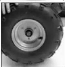
natural_image
Close-up of a large tire with visible tread pattern and central hub (no text or symbols)Räder:
natural_image
Front view of a wheeled vehicle chassis with two large tires and a mounted platform (no visible text or symbols)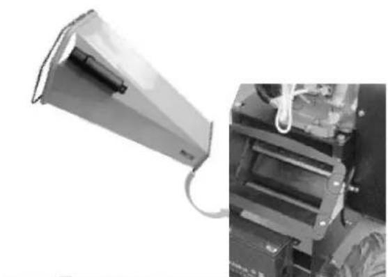
natural_image
Exterior view of a mechanical device with a triangular component and wiring, shown from an angle (no visible text or symbols)

natural_image
Close-up of mechanical components with four circular annotations highlighting features (no readable text or symbols)Achsen:
natural_image
Close-up of a mechanical device with visible components and a yellow arrow pointing to a component (no text or symbols)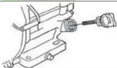
natural_image
Technical line drawing of a mechanical clamp or bracket assembly (no text or symbols)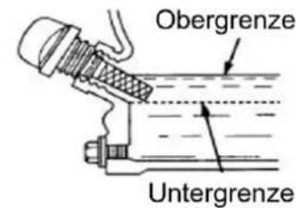
natural_image
Close-up of a metallic mechanical component with threaded end and flanged connectors (no visible text or symbols)This manual contains important information and advice for the correct and safe use and maintenance of the shredder ZI-HAEK4100 / ZI-HAEK11000.
Following the usual commercial name of the machine (see cover) is substituted in this manual with the name "machine".
The manual is part of the machine and may not be stored separately. Read it profoundly before first use of the machine and keep it for later reference. When the machine is handed to other persons always put the manual to the machine.
Please follow the security instructions!
Please read the entire manual, to prevent misunderstandings, machine damage or even injuries!

Due to continuous development of our products illustrations, pictures might differ slightly.
If you however find errors in this manual, please inform us.
Technical changes excepted!
Copyright law
© 2017
This manual is protected by copyright law – all rights reserved. Especially the reprinting as well as the translation and depiction of pictures will be prosecuted by law. Court of jurisdiction is the Landesgericht Linz or the competent court for 4707 Schlüsslberg, AUSTRIA.
Customer Support
The machine must only be used for its intended purpose! Any other use is deemed to be a case of misuse.
To use the machine properly you must also observe and follow all safety regulations, the assembly instructions, operating and maintenance instructions lay down in this manual.
All people who use and service the machine have to be acquainted with this manual and must be informed about the machine's potential hazards.
It is also imperative to observe the accident prevention regulations in force in your area.
The same applies for the general rules of occupational health and safety.
The machine is used for:
Shredding of branches of all kinds (depending on the type of wood and freshness). Wilted, moist, garden waste already stored several days alternating with tree branches.
This machines with drawbar are not approved for public road traffic!
Any manipulation of the machine or its parts is a misuse, in this case ZIPPER-MASCHINEN and its sales partners cannot be made liable for ANY direct or indirect damage.

WARNING
- Set during the operation could ensure that no foreign objects (such as stones, glass, metal, earth, and plastic) are filled into the shredder, such as foreign bodies blunt the chopping blade and severely damage the engine.
- Use your shredder solely for the purposes for which it was designed.
- The chopper should be carefully checked before use. Never use a chopper that is not in good condition if you notice a defect on the machine, which could pose a danger to the user, do not use the chopper until the defects have been corrected.
- This machine contains rotating blades.
- This blades does not stop immediately after stopping.
- The in-feed must be completely assembled and fixed prior to use.
Prohibited use:
- The operation of the machine outside the stated technical limits described in this manual is forbidden.
• Operation of the machine function without any protection devices is forbidden
• The use of the machine for any purposes other than described in this user-manual is forbidden. - Any manipulation of the machine and parts is forbidden.
- The use of the machine not being suitable for the use of the machine and not being certified is forbidden.
• It is not allowed to leave the immediate work area during the work is being performed!
11.2 Security instructions
Missing or non-readable security stickers have to be replaced immediately!
To avoid malfunction, machine defects and injuries, read the following security instructions!
The locally applicable laws and regulations may specify the minimum age of the operator and limit the use of this machine!
- Use the machine only in good enough light to allow a safe operation can be guaranteed.
- In tiredness, decreased concentration or under the influence of alcohol or drugs, the work on the machine is prohibited!
- Caution in slippery conditions - slip hazard - risk of injury. When working, robust and non-slip footwear. Slides / stumble / traps are a major cause of serious injury or death.
- Unauthorized persons, especially children and not trained personnel must be kept away from the running machine!
- The machine must be operated only by trained persons (knowledge and understanding of this manual), which have no limitations of motor skills compared with conventional workers.
- No other person and pets shall remain within 12m!
- If you pass the machine to third, these instructions must be attached to the machine.
- Before each use, the reliability of the machine is to be checked (tightness of the cutting tool, the proper function of the throttle lever, safety switch)
- Use personal safety equipment: ear protectors, safety gloves in EN 388, class 3111, safety shoes S1, safety goggles or face protection when working with the machine!
- Make sure that the device is completely and correctly assembled.
- Never leave the machine running unattended! Before leaving the working area switch the machine off and wait until the machine stops.
- Switch off the machine before maintenance or adjustment.
- The machine should be only during operation on solid level ground.
- Neither put your hands into the in-feed and discharge chute when the machine is running.
- Using your shredder only in places where it is protected from water and never use it during rain outdoors.
- Danger of burns! During the operation flow of hot exhaust gases and engine parts such as the muffler and engine become hot.
- WARNING: Gasoline is highly flammable!
- Stop the engine before refuelling
- Smoking and open flames are prohibited during refuelling.
- Do not refuel when the engine and carburettor are still very hot.
- Refuel only outdoors or in a well ventilated area.
- Avoid contact with skin and clothes (fire hazard)
- Check after refuelling tank cap and check for leaks.
- Start the engine at least 3 meters from the tank location.
- Spilled fuel is wipe immediately.
- Keep the fuel in suitable containers only
- Make sure the fuel does not overflow. If the fuel overflows, the engine must not be started. Remove any dirt from the appliance and prevent any attempt at ignition until fuel fumes have evaporated
- Damaged fuel tank or other tank cap must be replaced immediately
- After the operation the fuel cock must be closed (if available)
- Danger of Intoxication! Only use outdoors and far from open windows and vents!
- Exhaust contains poisonous carbon monoxide. The exposure can cause unconsciousness and death.
- Before the start, after the failure or shock, be sure to check the device and make sure that it is in good condition
Change damaged parts immediately
TRANSPORT NOTES:
- Switch off the engine and let cool down
- Never lift or carry the machine while the engine is running
- Wait till the blade are completely stopped
- Secure the machine
- Empty tank completely, avoid fuel spillage
- To avoid damage to the device never drag but always lift correctly.
STORAGE NOTES:
- Clean and dry the machine
- Empty tank completely, avoid fuel spillage
- Let cool down the engine
- Store in a dry, out of reach of children place, well packaged
- Do not store machines with fuels and fuels close to combustible and highly inflammable materials as well as sparks and open flames.
- Never remove the fuel tank cap when the engine is running or hot
Switch of the engine and remove the ignition key (if is available): - Before check, clean or work on the machine
■ Before eliminating faults - Before the start, after the failure or shock, be sure to check the device and make sure that it is in good condition
- If the shredder starts to vibrate abnormally, stop the engine immediately and locate the cause. Vibrations generally terminate in malfunction.
■ Before refuelling - Always if you leave the machine
11.3 Remaining risk factors

WARNING
It is important to ensure that each machine has remaining risks. In the execution of all work (even the simplest) greatest attention is required. A safe working depends on you!
Even if the machine is used as required it is still impossible to eliminate certain residual risk factors totally. The following hazards may arise in connection with the machine's construction and design:
- Risk of injury to the hands / fingers by negligent guiding the to be shredded material.
Guide the to be shredded material slowly and carefully into the in-feed. Automatic feeding! - Risk of injury: hair and loose clothing, etc. can be captured and wound up! Safety regulations must be observed with regard to clothing.
- Risk of injury by tilting the machine
- Risk of injury to the eye by flying debris, even with safety goggles.
- Risk of injury to the hearing by prolonged labor without hearing protection.
- Risk of burns: Touching the mufflers, exhaust and other machine components which can be hot after prolonged continuous operation or when the engine is hot cause severe burns.
These risk factors can be minimized through obeying all security and operation instructions, proper machine maintenance, proficient and appropriate operation by persons with technical knowledge and experience.
In spite of all safety is and remains her healthy common sense and their corresponding technical qualification / training for use of the machines most important safety factor!
12 ASSEMBLY
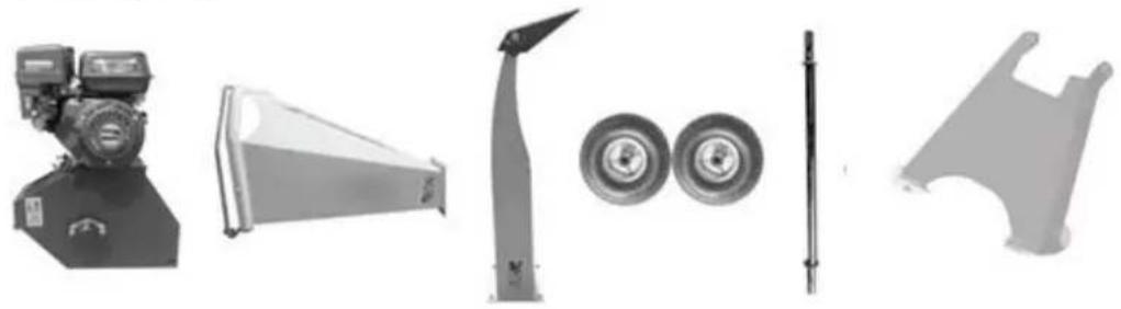
12.1 Delivery content
Please check the product contents immediately after receipt for any eventual transport damage or missing parts. Claims from transport damage or missing parts must be placed immediately after initial machine receipt and unpacking before putting the machine into operation. Please understand that later claims cannot be accepted anymore.
ZI-HAEK4100:
natural_image
Product catalog image showing five mechanical components: a pump, triangular fan, cylindrical wheel, flat rod, and curved bracket (no visible text or labels)ZI-HAEK11000:

natural_image
Collection of automotive components including a robotic arm, triangular frame, tire wheel, and mechanical bracket (no text or symbols visible)12.2 Assembly

NOTICE
Some machine components are heavier than 20kg. Assembly only from min. 2 persons! Assembly only with engine switched off!
ZI-HAEK4100:
natural_image
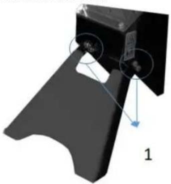
3D mechanical component with highlighted parts and label '1' (no text or symbols on the part itself)Base foot:
Tilt the blades chassis slightly backwards and fix the base foot with four screws, washers and nuts M10.
natural_image
Close-up of mechanical components including tire assembly, wheel rim, and conveyor belt (no visible text or symbols)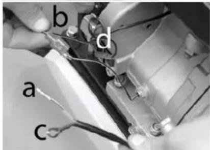
natural_image
Close-up of mechanical components with wires and connectors (no visible text or symbols)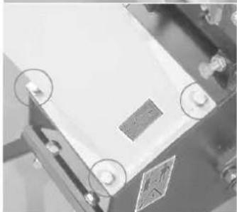
natural_image
Close-up of a mechanical component with circular annotations and a label (no readable text or symbols)Axis:
Tilt the blades chassis slightly forwards, push the axis through the bracket and fix with Allen screw, washer and nut.
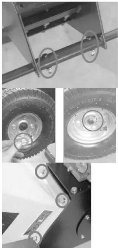
Wheels:
Place on both ends of the axis a washer. Push a wheel over the axis. Secure with a spacer and splint.
In-feed:
Place the in-feed on the blades chassis so that the mounting holes coincide with the holes on the in-feed. Fix with screws, washers and nuts.
Attention: Risk of cutting!
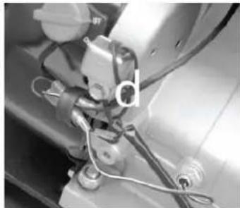
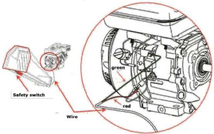
Safety switch:
Insert the cable (a) into the plug of the cable (b).
Then connect the cable (c) to the motor using screw (d).
Discharge chute:
Place the discharge chute on the blades chassis so that the mounting holes coincide with the holes on the discharge chute.
Fix with screws, washers and nuts.
ZI-HAEK11000:
natural_image
Close-up of a hand using a tool to adjust or install a mechanical component (no visible text or symbols)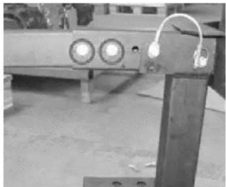
natural_image
Industrial equipment with circular components and a metal frame, no visible text or symbols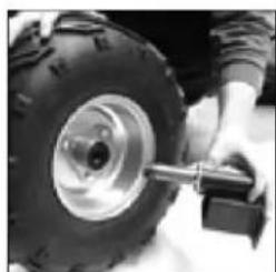
natural_image
Close-up of a person adjusting a tire with a mechanical lever (no visible text or symbols)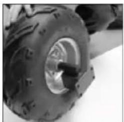
natural_image
Close-up of a small wheeled vehicle tire with visible tracks and mounting brackets (no text or symbols)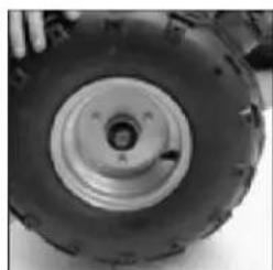
natural_image
Close-up of a large tire with central hub and visible tread pattern (no text or symbols)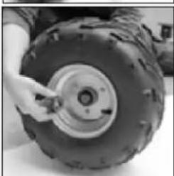
natural_image
Close-up of a person adjusting a large tire with a hand adjusting the wheel (no visible text or symbols)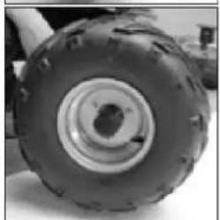
natural_image
Close-up of a large tire with visible tread pattern and central hole (no text or symbols)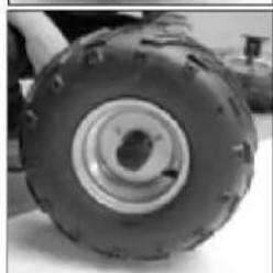
natural_image
Close-up of a large tire with visible tread pattern and central hole (no text or symbols)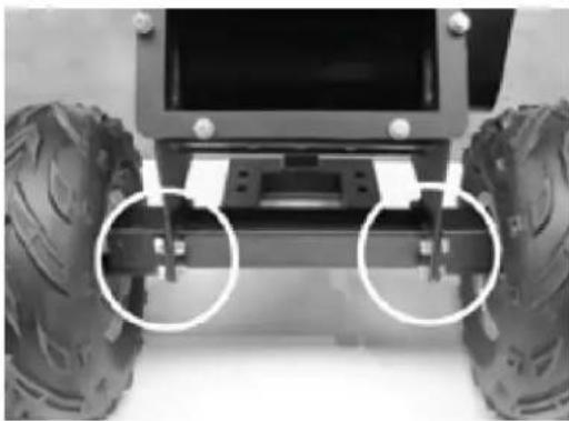
natural_image
Front view of a small wheeled vehicle chassis with two large tires and a mounted sensor or bracket (no visible text or symbols)Base foot:
Tilt the blades chassis slightly backwards and fix the base foot with screws, washers and nuts.
Drawbar:
Place the drawbar on the base foot and fix with screws M12x100, washers and nuts M12.
Wheels:
Push the axis through the rim, tighten the nut and secure with a splint.
Then fit the hubcap.
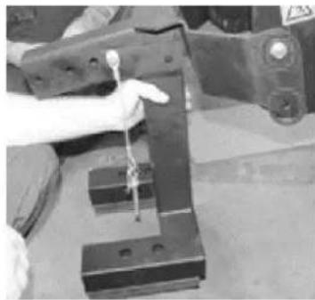
Axis:
Tilt the blades chassis slightly backwards and fix the axis with screws, washers and nuts.

natural_image
Exterior view of a mechanical device with a conical base and attached cable, alongside a close-up of its internal components (no visible text or symbols)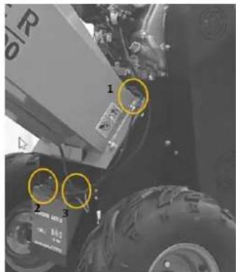
natural_image
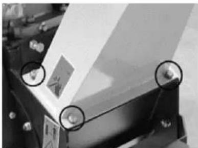
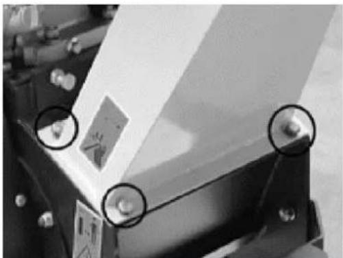
Close-up of mechanical components with circular annotations highlighting features (no readable text or symbols)In-feed:
Place the in-feed on the blades chassis so that the mounting holes coincide with the holes on the in-feed.
Fix with washers and nuts.
Attention: Risk of cutting!
Safety switch / battery connection:
Safety switch:
Establish the plug connection of the 2-pin plug (1)
Battery:
Connect the (+) and (-) poles of the starter cable to the one on the battery.
Discharge chute:
Place the discharge chute on the blades chassis so that the mounting holes coincide with the holes on the discharge chute. Fix with screws, washers and nuts.

WARNING
After finalized assembly check all screw connections and retighten if necessary!
12.3 Checklist before each use
NOT ICE

The use of paint thinners, petrol, aggressive chemicals or abrasives leads to material damage to the surfaces! Therefore use only mild detergents for cleaning!
- Clean the machine and remove dirt and dust if necessary.
- If the air filter is dirty, blow the filter cartridge from the inside by moving a jet of dry compressed air up and down. Continue until all dust has been removed. Replace the air filter with a new one if necessary.
- Check the carburettor for external dirt and dust and clean it with dry compressed air if necessary.
- Check the nuts and bolts for tightness. (Screws or bolts loosened by vibrations can lead to accidents!)
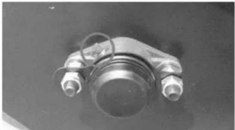
12.3.1 Checking the engine oil level
NOTICE

Too low an oil level will damage the engine and shorten the life of the machine. Therefore, check the engine oil level before every start and top up the engine oil if necessary.
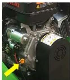
natural_image
Close-up of a mechanical engine component with visible gears and a yellow arrow pointing to a specific part (no text or symbols)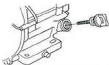
natural_image
Technical line drawing of a mechanical clamp or bracket assembly with a threaded connector (no text or symbols)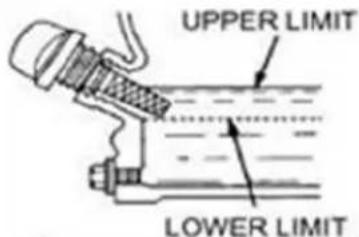
- To check the engine oil level, place the machine on a safe, level surface. Switch off the engine and allow the machine to stand for ten minutes so that the circulating oil can collect in the oil pan.
-
Unscrew the oil dipstick and wipe with a clean, lint-free cloth or a non-fibrous paper towel.
-
Push the dipstick into the opening, but do not screw it in. (Make sure that the dipstick has really been pushed in completely).
-
Pull out the oil dipstick again and read off the oil level. There are two markings for this - see illustration on the left.
-
If the oil level is low, refill the recommended oil up to the upper edge (maximum filling volume: approx. 0.5 litres).
-
Push in the oil dipstick again and tighten.
12.3.2 Checking the fuel tank level
NOT ICE

Observe the safety regulations for fuel control. Filter the fuel during refuelling to prevent foreign particles from entering the combustion chamber. Wipe up leaked fuel.
- Screw on the tank cap (sits on the fuel tank).
- Level check in the form of a visual inspection. If necessary, top up with fuel with the appropriate octane number (RON 95).
- Close the fuel filler cap tightly after refuelling.
13 OPERATION
Machine to be operated in a perfect state only. Inspect the device visually every time it is to be used. Check in particular the safety equipment, electrical controls, electric cables and screwed connection for damage and if tightened properly. Replace any damaged parts before operating the device.
13.1 Information on Initial Start-up
NOTICE

Note that the machine is delivered without engine oil and fuel. Make sure that this equipment is filled up before the machine is put into operation for the first time.
ATTENTION: The machine does not start until the engine oil has been refilled to the upper limit.
13.1.1 Test Run Initial Start-up
- Let the machine run idle for about 3 minutes.
- Pay attention to abnormal noises.
- Pay attention to the exhaust fumes (too black, too white)?
13.1.2 Notes on the first 20 operating hours
In order to optimize the life expectancy of your machine, the following points should be observed:
- Do not operate the engine for the first 20 operating hours @ maximum load (this also applies to used engines after extensive maintenance). This means lower speed and lower maximum working load than during normal operation.
- Change the engine oil after the first 20 hours of operation.
13.2 Operation instructions
WAR NI NG
Stop the machine before any break, maintenance and cleaning! The safety switch must be rightly connected! RISK OF INJURY!

NOT ICE
- Do not stand in the discharge chute area during starting the machine
- Before starting check that the in-feed the free from any material
- Start shredding after the engine has reached full speed
- Operating only with sharp blades
- Use only blades allowable for this machine!
- Never use damaged blades!
• Always operate in the operator zone - Never stay in the in-feed zone
- Never use the recoil-starter while the engine is running. This will damage the engine
- Do not operate the machine on slopes of more than 20°, as even with an optimum oil level the engine may not be supplied with sufficient lubrication.

Connection of safety switch:
13.3 Operation
13.3.1 Refuel, start, stop
See also the operation manual of the engine manufacturer
Starting the machine
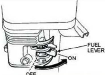 | 1. Turn the fuel valve to the "ON" position. |
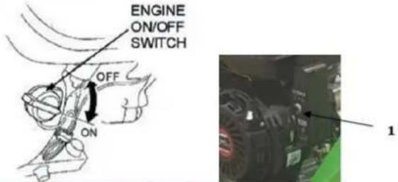 | 2. Set the engine ON/OFF switch (ignition switch) also to the "On" position.(only for ZI-HAEK4100)Turn the key (1) to I-Position (only for ZI-HAEK11000) |
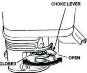 | Note: The closed position of the choke lever enriches the fuel mixture for starting a cold engine. The open position provides the correct fuel mixture for normal operation after starting and for restarting a warm engine.3. Turn the choke lever to the "Closed" position, only for cold engine. |
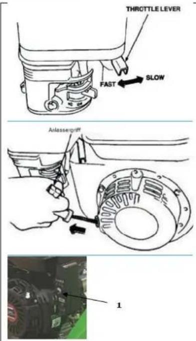
- Set the throttle lever to "half throttle" (= middle position between "fast" and "slow").
Note: Do not pull the starter rope through to the end and do not let it rewind after pulling, but only rewind it quickly.
- Grab the starter handle and pull it out slowly. The resistance becomes strongest at a certain point. This point corresponds to the compression point. Let the rope roll back a little from this point and then pull it out powerfully.
Only for ZI-HAEK11000 (elektronic START): Turn the Key from Position I to Start.
- Turn the choke lever to "Open when the engine is running.
Open throttle further to increase the speed before working with the Machine.
Stopping the Macchine:
Emergency-stop:
In case of danger and/or in an emergency situation, you can quickly stop the machine by pressing the infeed emergency stop.
Normal stop
- Set the throttle lever to "minimum" and let the engine run idle for approx. 3 minutes at low engine speed.
- Then set the engine ON/OFF switch (ignition switch) to the OFF position. Only for ZI-HAEK11000: Turn the key (1) from position I to 0.
- Close the fuel switch.
- Wait until the engine has cooled down before storing the machine.

NOTICE
• To wet material causes clogging
- Insert the to be shredded material into the in-feed and when the material is gripped by the machine and automatically feeded, release the material immediately
• Always feed in material with the thick end first
- Saw off long side branches and insert them separately
- Never work with too much pressure
- Do not overload the machine
- In the event of blockages, switch off the engine immediately and eliminate any malfunctions.
- Remove crosswise lying material only when the engine is switched off and the blades are stopped!
- Switch off the engine immediately if there are any unusual noise and vibrations. Repair any faults immediately.
After finishing the shredder work let the machine sufficient time to process the whole shredding material. This avoids start-up difficulties when working next time!
To be shredded:
Hedge and tree cuttings, bushes, perennial herb, dead flowers
To be not shredded:
Glass, metal, plastic, plastic bags, stones, cloth, roots with soil, food left-overs, fish or meat.
14 MAINTENANCE


ATTENTI ON
No cleaning, upkeep, checks or maintenance when machine is running Shut off the machine, let it cool down, disconnect spark plug cap from spark plug!
The machine does not require intense maintenance. However, to ensure a long lifespan, we strongly recommend following the upkeep and maintenance plan.
Repairs must be carried out by specialists! Use original ZIPPER parts only!
NOTICE
Only a properly maintained equipment may be a satisfactory tool. Care and maintenance deficiencies can cause unpredictable accidents and injuries.
Repairs should be performed only by authorized service centers.
Improper operation may damage the equipment or endanger your safety.
14.1 Maintenance plan
| Controls for the maintenance of the machine | |
| Loose or lost screws, nuts, bolts | Regularly prior to each operation |
| Damage of any part of the machine | Regularly prior to each operation |
| Fuel level | Regularly prior to each operation |
| Fuel tank of tightness | Regularly prior to each operation |
| Machine cleaning | Regularly prior to each operation |
| Oil level | Regularly prior to each operation |
| Function of safety switch | Every month |
| Tension of the V-belt | Regularly prior to each operation |
| Greasing of the blade drum | Every 25 working hours |
| Cleaning spark plug | Every 25 working hours |
| Cleaning air filter | Every 20-30 working hours |
14.1.1 Cleaning the air filter
A clogged air filter reduces the engines power output drastically and causes engine disfunction. Furthermore it reduces the engines lifespan!
Disassemble the air filter cap. Remove the air filter from the machine. Clean the air filter and drip some drops of oil onto the filter. Mount the filter back.
14.1.2 Cleaning the spark plug
Take off the spark plug cap. Loosen and remove the spark plug. Clean it with a small brush from soot debris. The contact distance shall account approx. 0, 5mm - 0,7mm.
14.1.3 Greasing of the blade drum
Grease the bearings of the blade drum on both sides to the grease nipple. Also after every cleaning!
- Remove V-belt cover.
- Clean grease nipple with cloth
- Apply the grease gun and pump the grease
- Reassemble the V-belt cover
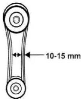
14.1.4 Adjusting the V-belt
natural_image
Close-up of a metallic mechanical component with threaded end and two bolts (no visible text or symbols)The V-belt connects the engine and blade drum. Especially with new machines or even after the change of the v-belt this itself is getting wider and loses purchase. If the V-belt yields more than 10-15mm on thumb pressure, it is necessary to adjust the V-belt again.
- Switch off the machine and take off the cover of the belt.
- Loose the four nuts at the engine.
- Move back the engine for straining and forward to solve the V-belt.
- Put the engine and drive pulley in liner (a ruler can be helpful). Tighten the four nuts at the engine again.
- Fix the cover of the V-belt again.
14.1.5 Blades

NOTICE
- Wear safety gloves.
- After approx. 30-50 working hours, the blades are blunt under normal operating conditions.
- Blades are blunt if:
○ abnormal noise
- decreased speed
○ V-belt (despite correct tension) slips
- Drum blades and counter blade can be turned 1 time

- Replace damaged blades immediately!
Loosen the screws, turn the blades (grind if necessary) and retighten the blades. Adjust counter blade cutting gap to 0,5 mm.
14.1.6 Carburettor
NOT ICE
Carburetor settings must be performed only by trained personnel!
14.1.7 Refuel
Each normal petrol (unleaded petrol) with octane index (ROZ) of 95 can be used. Never use a mix of oil and petrol or dirty petrol. Avoid infiltration of the gasoline tank by water, dust or dirt.
NOT ICE
It is not recommended to use alternative for gasoline, because this can cause damage of parts of the gasoline system.
14.1.8 Cleaning
Clean the machine and the working attachment from dirt.
Clean the machine housing with a wet cloth and a mild cleaning solution.
Put on all coatless flats a thin coat of oil.
NOTICE
The usage of solvents, aggressive chemicals or scouring agents damages the machine housing.
14.1.9 Storage
If the machine is stored for longer than 30 days:
- Let the machine cool down
- Clean the machine and dry
- Empty Tank and carburetor completely, avoid fuel spillage
- Store in a dry, out of reach of children place, well packaged.
14.1.10 Disposal
Do not dispose the machine in residual waste. Contact your local authorities for information regarding the available disposal options. Avoid damage caused by leaking operating supplies: drain the operating supplies prior to disposal! When you buy at your local dealer for a replacement unit, the latter is obliged to exchange your old.
15 TROUBLE SHOOTING

ATTENTION
Shut off the machine, let it cool down, disconnect spark plug cap from spark plug
| Trouble | Possible cause | Solution |
| Engine does not start | Ignition switch defect | Repair or change |
| No fuel | Refuel | |
| Spark plug dirty or damaged | Clean or change | |
| Fuel line faulty | Check fuel line for damage and kinks | |
| less engine oil (CAUTION: engine protection device) | Fill up engine oil to maximum | |
| To low power | Air filter dirty | Clean or change |
| V-belt | Tighten or change | |
| Overload | Reduce material feeding | |
| Blockage | Remove shredded material | |
| Blades blunt | Turn/grind blades | |
| No automatically feeding of the shredded material | Blades blunt | Turn/grind blades |
| Extra-ordinary sounds | Screws, nuts or other parts are slack | Fix parts |

NOT ICE
Should you in necessary repairs not able to properly to perform or you have not the prescribed training for it always attract a workshop to fix the problem.
16 PREFACIO (ES)
Estimado Cliente,
natural_image
Product catalog image showing five mechanical components: a pump, triangular fan, wheel rim, two wheels, and a curved bracket (no visible text or labels)ZI-HAEK11000:

natural_image
Collection of automotive components including a robotic arm, triangular frame, tire assembly, and mechanical bracket (no visible text or symbols)18.2 Montaje

NOTA
natural_image
3D mechanical component with highlighted parts and numbered label (1), no readable text or symbols presentPie base:
natural_image
Close-up of mechanical components with wires and connectors (no visible text or symbols)Eje:
natural_image
Close-up of a hand using a tool to adjust or install a mechanical component (no visible text or symbols)
natural_image
Industrial equipment with circular light fixtures and a metal frame, no visible text or symbolsPie base:
natural_image
Close-up of a person adjusting a large tire with a hand holding the nut (no visible text or symbols)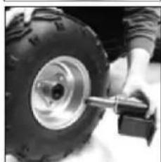
natural_image
Close-up of a person using a tire to lift a large wheel (no visible text or symbols)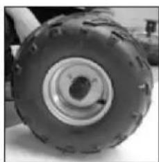
natural_image
Close-up of a mechanical tire with visible tread pattern and central bore (no text or symbols)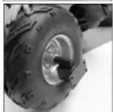
natural_image
Close-up of a large tire with visible tracks and tread pattern (no text or symbols)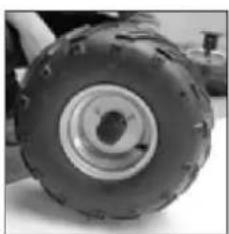
natural_image
Close-up of a large tire with visible tread pattern and central hub (no text or symbols)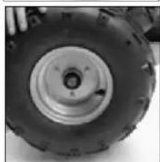
natural_image
Close-up of a large agricultural tire with visible tread pattern and central bore (no text or symbols)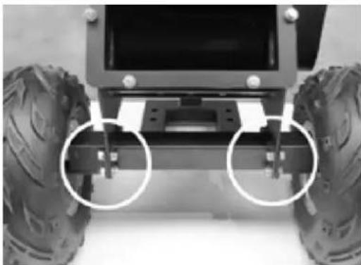
natural_image
Front view of a wheeled vehicle chassis with two large tires and mounting brackets (no visible text or symbols)Ruedas:
natural_image
Exterior view of a mechanical device with a conical component and wiring (no visible text or symbols)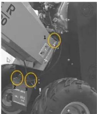

natural_image
Close-up of mechanical components with circular annotations highlighting features (no readable text or symbols)natural_image
Close-up of a mechanical engine component with visible gears and a yellow arrow pointing to a specific part (no text or symbols)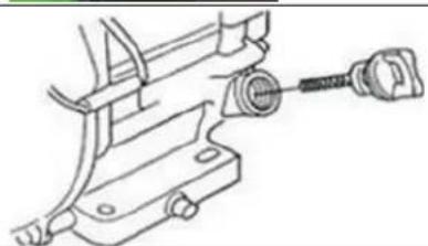
natural_image
Technical line drawing of a mechanical clamp or bracket assembly (no text or symbols)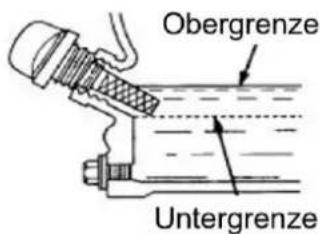
19.1 Funcionamiento
19.1.1 Repostar, arrancar, apagar
natural_image
Close-up of a metallic mechanical component with threaded end and two bolts (no visible text or symbols)INFORMATIONS POUR LE TRANSPORT:
natural_image
Product catalog image showing five mechanical components: a pump, triangular fan, wheel rim, two wheels, and a curved bracket (no visible text or labels)ZI-HAEK11000:

natural_image
Collection of automotive components including a robotic arm, spray gun, tire wheel, and mechanical bracket (no text or symbols visible)24.2 Assemblage

NO TE
natural_image
3D mechanical component with highlighted parts and label '1' (no text or symbols on the part itself)Pied de base:
natural_image
Close-up of mechanical components with wires and a labeled part 'd' (no readable text or symbols)Axe:
natural_image
Close-up of a hand using a tool to adjust or install a mechanical component (no visible text or symbols)
natural_image
Industrial metal frame with two circular light fixtures and a vertical support structure (no visible text or symbols)Pied de base:
natural_image
Close-up of a person adjusting a large tire with a hand holding the nut (no visible text or symbols)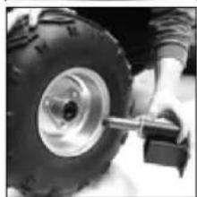
natural_image
Close-up of a person adjusting a large off-road tire with a valve (no visible text or symbols)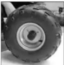
natural_image
Close-up of a large tire with visible tread pattern and central hole (no text or symbols)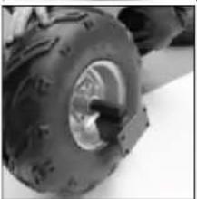
natural_image
Close-up of a small wheeled vehicle tire with visible tread pattern and central wheel (no text or symbols)
natural_image
Close-up of a large industrial tire with visible tread pattern and central bore (no text or symbols)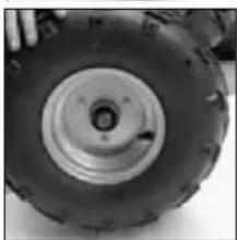
natural_image
Close-up of a large off-road tire with visible tread pattern and central hub (no text or symbols)
natural_image
Front view of a wheeled vehicle chassis with two large tires and mounting brackets (no visible text or symbols)Roues:
natural_image
Exterior view of a mechanical device with a triangular component and wiring, shown alongside an inset image of a mechanical assembly (no visible text or symbols)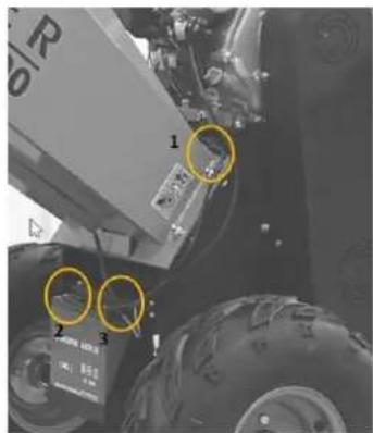
natural_image
Close-up of mechanical components with circular annotations highlighting features (no readable text or symbols)natural_image
Close-up of a mechanical engine component with visible wiring and mounting features (no text or symbols)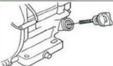
natural_image
Technical line drawing of a mechanical clamp or bracket assembly (no text or symbols)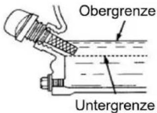
25.3 Fonctionnement
natural_image
Close-up of a metallic mechanical component with threaded end and two bolts (no visible text or symbols)(EN) With original ZIPPER spare parts you use parts that are attuned to each other shorten the installation time and elongate your machines lifespan.
IMP OR TAN T
The installation of other than original spare parts voids the warranty!
So you always have to use original spare parts
When you place a spare parts order please use the service formular you can find in the last chapter of this manual. Always take a note of the machine type, spare parts number and partname. We recommend to copy the spare parts diagram and mark the spare part you need.
You find the order address in the preface of this operation manual.
| No. | Description | No. | Description |
| 1 | Base Frame | 20 | M8x15 Rubber |
| 2 | Roller | 21 | M8x15 Rubber |
| 3 | Drum Blade | 22 | Chute Deflector |
| 4 | M10x25 Hex Bolt | 23 | Engine |
| 5 | M12x40 Hex Bolt | 24 | Engine Base Plate |
| 6 | Bearing Mount Plate | 25 | In-Feed to Frame Rubber |
| 7 | Bearing | 26 | In-Feed Chute |
| 8 | Pulley | 27 | In-Feed Chute |
| 9 | Clutch | 28 | Switch Cover |
| 10 | Belt | 29 | Rubber Chip Baffle |
| 11 | Belt Cover | 30 | Rubber Baffle Mount |
| 12 | Wheel Axis | 31 | Switch |
| 13 | Tire | 32 | Spring |
| 14 | Belt Inner Cover | 33 | Switch Frame |
| 15 | Rubber Pad | 34 | Guide Plate |
| 16 | Support Leg | 35 | Bed Knife |
| 17 | Discharge to Frame Rubber | 36 | Lower Blade Fixed Angel Steel |
| 18 | Discharge Chute | 37 | M10x25 Hex Bolt |
| 19 | Discharge Chute |
28.2.2 ZI-HAEK11000
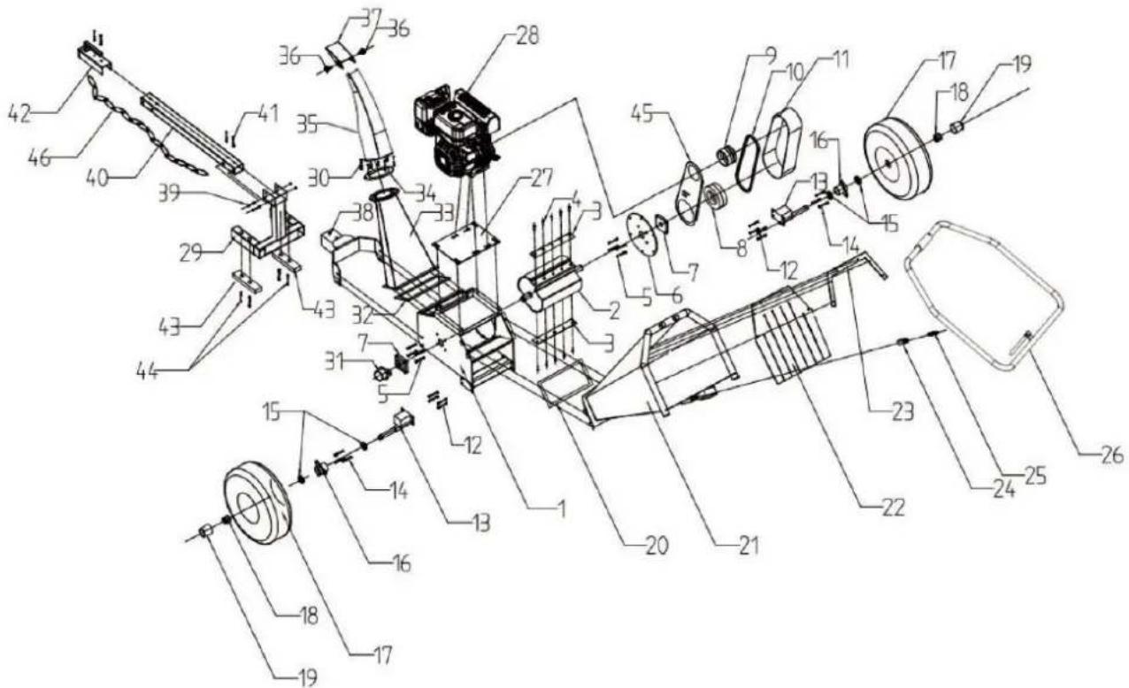
| No. | Description | No. | Description |
| 1 | Base Frame | 29 | Support Leg |
| 2 | Roller | 30 | M6x25 Hex Bolt |
| 3 | Drum Blade | 31 | Bearing Cover |
| 4 | M10x25 Hex Bolt | 32 | Discharge to Frame Rubber |
| 5 | M12x40 Hex Bolt | 33 | Discharge Chute |
| 6 | Bearing Mount Plate | 34 | Flange to Discharge Chute |
| 7 | Bearing | 35 | M8x15 Handle Bolt |
| 8 | Pulley | 36 | M8x15 Rubber |
| 9 | Clutch | 37 | Chute Deflector |
| 10 | 17x1041Li Belt | 38 | Tongue Base |
| 11 | Belt Cover | 39 | M10x70 Hex Bolt |
| 12 | M10x25 Hex Bolt | 40 | Tow Bar |
| 13 | Wheel Axis | 41 | M10x60 Hex Bolt |
| 14 | M8x25 Hex Bolt | 42 | Tow Hitch for 2" Ball |
| 15 | Wheel Bearing | 43 | Rubber Pad |
| 16 | Wheel Flange | 44 | M8x30 Hex Bolt |
| 17 | 16x8.00-7 Tire | 45 | Belt Inner Cover |
| 18 | M24x1.5 Castle Nut | 46 | Safety Chains |
| 19 | Wheel Rubber Cap | 47 | Battery |
| 20 | In-Feed to Frame Rubber | 48 | Bed Knife |
| 21 | In-Feed Chute | 49 | Switch cover |
| 22 | Rubber Chip Baffle | 50 | M12x80 Hex Bolt |
| 23 | Rubber Baffle Mount | 51 | Rubber Pad |
| 24 | Limit Switch | 52 | Battery cover |
| 25 | Spring | 53 | M8x20 Hex Bolt |
| 26 | Switch Frame | 54 | Lower Blade Fixed Angel Steel |
| 27 | Engine Base Plate | 55 | M10x25 Hex Bolt |
| 28 | Petrol Engine |
Company ZIPPER Maschinen GmbH grants for mechanical and electrical components a warranty period of 2 years for amateur use; and warranty period of 1 year for professional use, starting with the purchase of the final consumer. In case of defects during this period, which are not excluded by paragraph 3, ZIPPER will repair or replace the machine at its own discretion.
2.) Report:
In order to check the legitimacy of warranty claims, the final consumer must contact his dealer. The dealer has to report in written form the occurred defect to ZIPPER. If the warranty claim is legitimate, ZIPPER will pick up the defective machine from the dealer. Returned shippings by dealers which have not been coordinated with ZIPPER, will not be accepted and refused.
3.) Regulations:
a) Warranty claims will only be accepted, when a copy of the original invoice or cash voucher from the trading partner of ZIPPER is enclosed to the machine. The warranty claim expires if the accessories belonging to the machine are missing.
b) The warranty does not include free checking, maintenance, inspection or service works on the machine. Defects due to incorrect usage of the final consumer or his dealer will not be accepted as warranty claims either. Some examples: usage of wrong fuel, frost damages in water tanks, leaving fuel in the tank during the winter, etc.
c) Defects on wear parts are excluded, e.g. carbon brushes, collection bags, knives, cylinders, cutting blades, clutches, sealings, wheels, saw blades, splitting crosses, riving knives, riving knife extensions, hydraulic oils, oil/air/fuel filters, chains, spark plugs, sliding blocks, etc.
d) Also excluded are damages on the machine caused by incorrect or inappropriate usage, if it was used for a purpose which the machine is not supposed to, ignoring the user manual, force majeure, repairs or technical manipulations by not authorized workshops or by the customer himself, usage of non-original ZIPPER spare parts or accessories.
e) After inspection by our qualified personnel, resulted costs (like freight charges) and expenses for not legitimated warranty claims will be charged to the final customer or dealer.
f) In case of defective machines outside the warranty period, we will only repair after advance payment or dealer's invoice according to the cost estimate (incl. freight costs) of ZIPPER.
g) Warranty claims can only be granted for customers of an authorized ZIPPER dealer who directly purchased the machine from ZIPPER. These claims are not transferable in case of multiple sales of the machine.
4.) Claims for compensation and other liabilities:
The liability of company ZIPPER is limited to the value of goods in all cases. Claims for compensation because of poor performance, lacks, damages or loss of earnings due to defects during the warranty period will not be accepted. ZIPPER insists on its right to subsequent improvement of the machine.
32 GARANTÍA Y SERVICIO (ES)
1.) Garantía:
Product experience form
We observe the quality of our delivered products in the frame of a Quality Management policy.
Your opinion is essential for further product development and product choice. Please let us know about your:
- Impressions and suggestions for improvement.
- experiences that may be useful for other users and for product design
- Experiences with malfunctions that occur in specific operation modes
We would like to ask you to note down your experiences and observations and send them to us via FAX, E-Mail or by post:
Erworben von / purchased from:
E-Mail/ e-mail:
Please describe amongst others in the problem: What has cause the problem/defect, what was the last activity before you noticed the problem/defect? For electrical problems: Have you had checked you electric supply and the machine already by a certified electrician?
3. Bitte beachten
/ Additional information
INCOMPLETELY FILLED SERVICE FORMS CANNOT BE PROCESSED! FOR GUARANTEE CLAIMS PLEASE ADD A COPY OF YOUR ORIGINAL SALES / DELIVERY RECEIPT OTHERWISE IT CANNOT BE ACCEPTED. FOR SPARE PART ORDERS PLEASE ADD TO THIS SERVICE FORM A COPY OF THE RESPECTIVE EXPLODED DRAWING WITH THE REQUIRED SPARE PARTS BEING MARKED CLEARLY AND UNMISTAKABLE. THIS HELPS US TO IDENTIFY THE REQUIRED SPARE PARTS FASTLY AND ACCEL- LERATES THE HANDLING OF YOUR INQUIRY.