PA0840M - Air-conditioner SIEMENS - Free user manual and instructions
Find the device manual for free PA0840M SIEMENS in PDF.
| Product type | Portable air conditioner |
| Brand | Siemens |
| Model | PA0840M |
| Power supply | 220-240 V, 50 Hz, grounded plug |
| Electrical protection | 10 A slow-blow fuse |
| Operating modes | Cooling, dehumidification, purification, ionization |
| Temperature range (cooling mode) | 18 °C to 30 °C in 1 °C increments |
| Available speeds | 5 manual speeds + 2 automatic speeds (max and silent) |
| Maximum exhaust hose length | 140 cm |
| Filter type | Washable basic filter + double active filter (optional) |
| Water tank | Removable with full level sensor |
| Ionizer | Built-in, can be turned on/off |
| Timer | Programmable (on, off, on/off) |
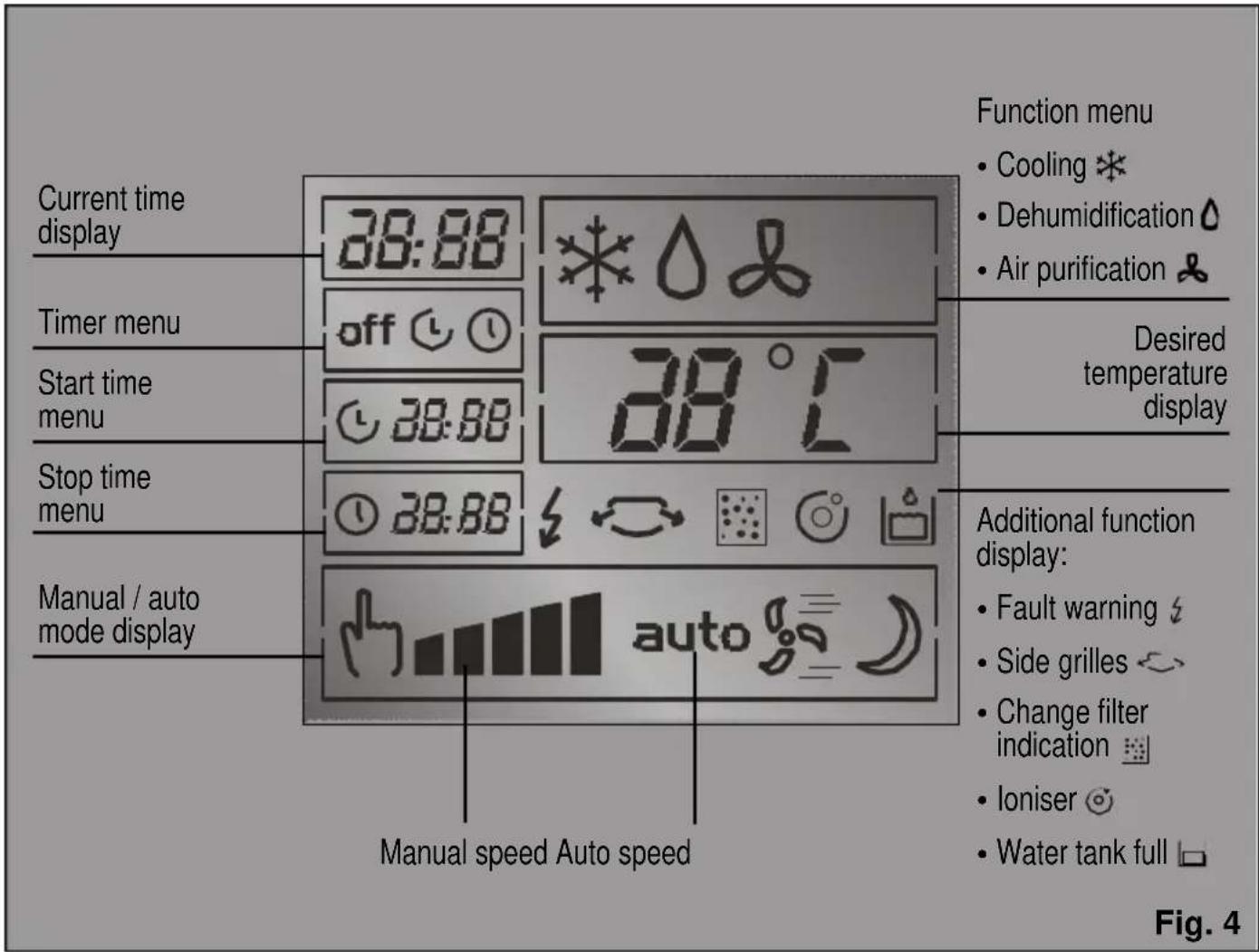
| Display | Digital screen (temperature, time, speed, functions) |
| Side louvers | Adjustable with dedicated control |
| Wheels | Yes, for easy moving |
| Minimum distance to surfaces | 20 cm |
| Compressor wait time | 3 minutes after shutdown |
| Included accessories | Exhaust hose, diffuser, suction cup, window/balcony slider |
| Cleaning | Soft cloth, lukewarm water, mild detergent; washable filter with water |
| Warranty | According to country conditions, proof of purchase required |
Frequently Asked Questions - PA0840M SIEMENS
User questions about PA0840M SIEMENS
0 question about this device. Answer the ones you know or ask your own.
Ask a new question about this device
Download the instructions for your Air-conditioner in PDF format for free! Find your manual PA0840M - SIEMENS and take your electronic device back in hand. On this page are published all the documents necessary for the use of your device. PA0840M by SIEMENS.
USER MANUAL PA0840M SIEMENS
Instructions for Use
Mode d'emploi
natural_image
3D rendering of a Siemens industrial air purifier unit (no text or symbols on the device itself)PA0840M
natural_image
Symbol of a trash bin crossed with two diagonal lines, no text or labels present
natural_image
3D diagram of a mechanical device with a bracket and pipe, showing a white arrow pointing to a component (no text or symbols)natural_image
3D mechanical assembly diagram showing internal components and a labeled section (no text or symbols on the diagram itself)Achtung!
natural_image
3D rendering of a mechanical component with a cylindrical housing and a base plate, shown with an arrow indicating rotation (no text or symbols)natural_image
3D rendered mechanical component with threaded cylindrical body and mounting base, labeled Abb. 12 (no text or symbols on the object itself)natural_image
Illustration of a hand holding a flexible hose to install a window frame (no text or symbols visible)natural_image
Exterior view of a door with a side panel and label Abb. 15 (no other text or symbols)Festinstallation
natural_image
3D rendering of a printer or printer with ventilation ducts and a labeled section (no readable text or symbols)flowchart
graph TD
    A["Top Lane"] --> B["Left Path with Traffic Light Icon"]
    B --> C["Right Path with Auto icon"]
    C --> D["Bottom Lane"]
    style A fill:#f9f,stroke:#333
    style D fill:#bbf,stroke:#333
natural_image
3D rendering of a rectangular plastic enclosure with four compartments (no text or symbols)Abb. 20
ACHTUNG!!!!
natural_image
Technical diagram showing a mechanical assembly with an inset magnified view of a building facade detail (no text or symbols present)natural_image
Simple line drawing of a 3D rectangular prism with a curved arrow pointing to its top face (no text or symbols)Abb. 22
natural_image
Diagram of a window frame with three upward-pointing arrows indicating movement or force, no text or symbols present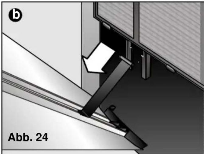
natural_image
Technical diagram showing a mechanical assembly with an arrow indicating direction, labeled 'Abb. 24' (no readable text or symbols beyond label)natural_image
3D rendering of a Siemens industrial device with coiled tubing and housing (no visible text or symbols)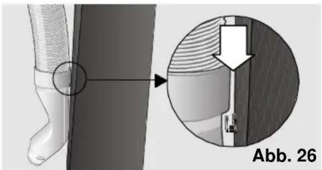
natural_image
Technical illustration of a mechanical component with cross-sectional view and magnified detail (no text or symbols)Environmental protection
Recommendations for the disposal of packaging......27
Recommendations for the disposal of your old appliance.....27
Recommendations for saving energy 27
Important Information
Before connecting your appliance ....28
If there are children in the home....28
Your new appliance
Description of the appliance ....29
Control panel....30
Description of accessories....31
Requirements for use
Requirements for use....31
Navigation
"Up" and "down" keys....32
"+" and "-" keys....32
Instructions for Use
Preparing the appliance before use....33
Turning the appliance on and off 35
Selecting the operation function ....35
Cooling....36
Dehumidification....36
Air purification ....37
Ionisation....37
Selecting the temperature....38
Selecting the speed ....38
Side fins....39
Setting the clock / Programming the timer....39
Cleaning, Transportation and Maintenance
Cleaning the appliance ....43
Cleaning and changing the purifying filters....43
Transportation requirements....45
Storage requirements ....45
Prior to use at change of season....45
Technical Service / Warranty 45
Things to check before calling the Technical Service
General operation....46
Noise....46
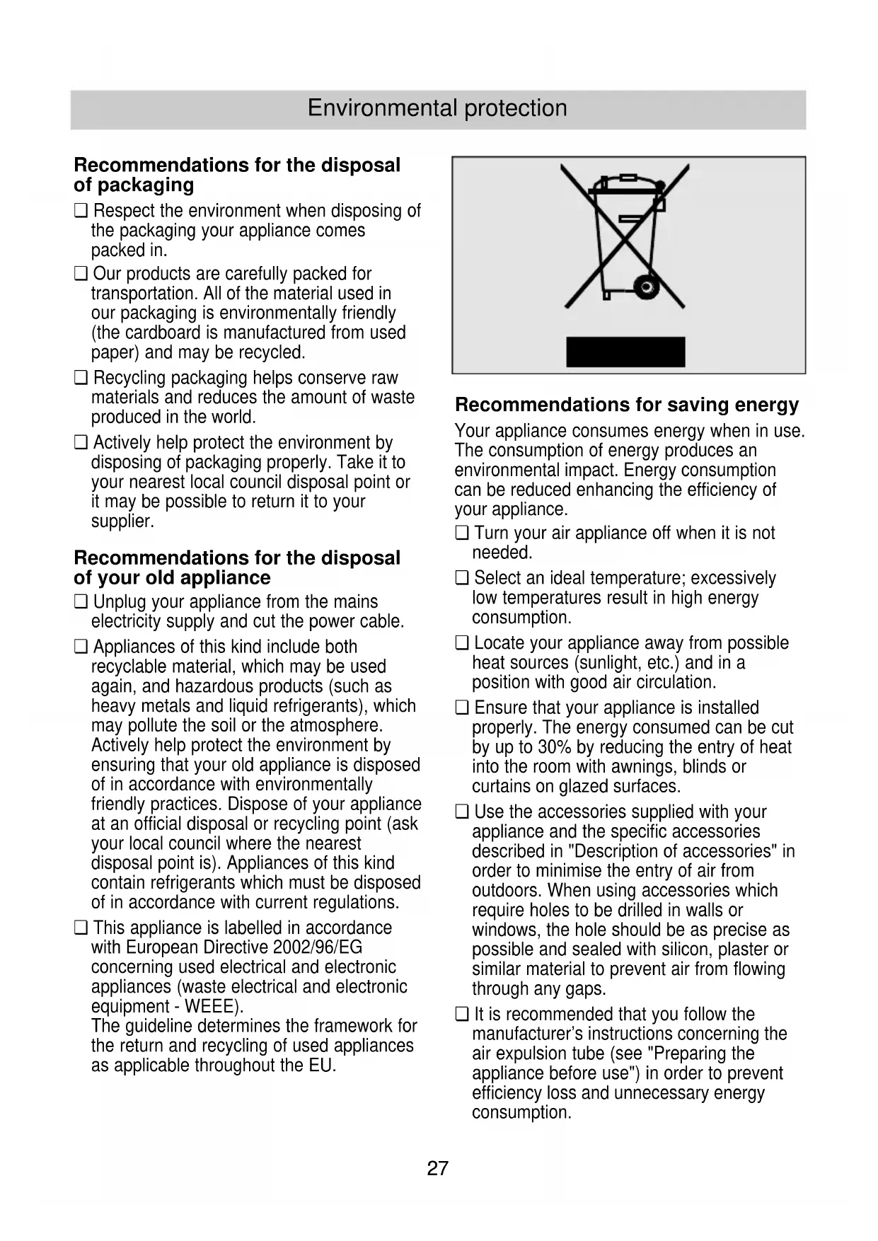
Recommendations for the disposal of packaging
☐ Respect the environment when disposing of the packaging your appliance comes packed in.
☐ Our products are carefully packed for transportation. All of the material used in our packaging is environmentally friendly (the cardboard is manufactured from used paper) and may be recycled.
□ Recycling packaging helps conserve raw materials and reduces the amount of waste produced in the world.
□ Actively help protect the environment by disposing of packaging properly. Take it to your nearest local council disposal point or it may be possible to return it to your supplier.
Recommendations for the disposal of your old appliance
□ Unplug your appliance from the mains electricity supply and cut the power cable.
□ Appliances of this kind include both recyclable material, which may be used again, and hazardous products (such as heavy metals and liquid refrigerants), which may pollute the soil or the atmosphere. Actively help protect the environment by ensuring that your old appliance is disposed of in accordance with environmentally friendly practices. Dispose of your appliance at an official disposal or recycling point (ask your local council where the nearest disposal point is). Appliances of this kind contain refrigerants which must be disposed of in accordance with current regulations.
☐ This appliance is labelled in accordance with European Directive 2002/96/EG concerning used electrical and electronic appliances (waste electrical and electronic equipment - WEEE). The guideline determines the framework for the return and recycling of used appliances as applicable throughout the EU.
natural_image
Symbol of a trash bin crossed with no text or labels
Recommendations for saving energy
Your appliance consumes energy when in use. The consumption of energy produces an environmental impact. Energy consumption can be reduced enhancing the efficiency of your appliance.
☐ Turn your air appliance off when it is not needed.
□ Select an ideal temperature; excessively low temperatures result in high energy consumption.
☐ Locate your appliance away from possible heat sources (sunlight, etc.) and in a position with good air circulation.
☐ Ensure that your appliance is installed properly. The energy consumed can be cut by up to 30% by reducing the entry of heat into the room with awnings, blinds or curtains on glazed surfaces.
☐ Use the accessories supplied with your appliance and the specific accessories described in "Description of accessories" in order to minimise the entry of air from outdoors. When using accessories which require holes to be drilled in walls or windows, the hole should be as precise as possible and sealed with silicon, plaster or similar material to prevent air from flowing through any gaps.
It is recommended that you follow the manufacturer's instructions concerning the air expulsion tube (see "Preparing the appliance before use") in order to prevent efficiency loss and unnecessary energy consumption.
Environmental protection
☐ Avoid sharp bends on the air expulsion tube and do not lengthen it more than necessary.
☐ When expelling hot air through sliding windows, install the accessory which prevents hot air entering the room from outdoors and enhances efficiency.
☐ Make sure that the diffusion duct is positioned in such a way that the window can be closed as far as possible in order to prevent air from outdoors entering the room.
☐ Check that the sleeves (collection and diffusion) are correctly joined to the air expulsion tube. See "Preparing the appliance".
□ Make sure that the air intakes and outlets are not obstructed. Keep them clean and free of dirt, dust and foreign objects.
□ Make sure that the filters fitted on your appliance are clean and installed properly (see "Cleaning and Maintenance").
☐ In the summer, ventilate the building when the air outdoors is at its coolest (early morning, night).
Important Information
Before connecting your appliance
☐ Read the instructions book before using the appliance for the first time. It contains important information concerning not only how to use the appliance, but also maintenance and personal safety.
□ Keep this instructions book. It may be needed by another user at a later date.
☐ Do not use the appliance when damaged.
☐ Your appliance should be assembled and connected to the mains electricity supply in accordance with the assembly instructions and current regulations. You may lose your warranty if you fail to observe these instructions.
☐ Our appliances are manufactured in accordance with current safety regulations. Only technicians instructed in these matters are authorised to repair them. Your safety is at stake.
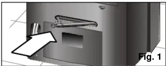
☐ Make sure that the drainage plug is fully inserted. It may have come loose during transportation, Fig. 1.
natural_image
3D diagram of a mechanical device with a bracket and mounting holes, labeled Fig. 1 (no text or symbols on the device itself)☐ The manufacturer informs that these appliances are exclusively intended for household and/or commercial use, commercial being understood as offices or rooms, the size and characteristics of which comply with those specified in the commercial catalogues.
☐ The use of this appliance is not guaranteed for industrial environments, industrial being understood as large areas or in the proximity of non-ambient heat sources (elements, heaters, etc.).
If there are children in the home
☐ The front flap and the air-conditioning appliance must not be sat upon, climbed on or leant against. The appliance may fall over, hurting persons and/or damaging objects.
☐ Do not allow children to play or tamper with the air-conditioning appliance.
□ Keep small children away from the air-conditioning appliance, particularly when the front flap is open, to prevent them from hanging from or leaning against it. It may fall over.
☐ Do not allow children to play with or insert objects in the air outlets or any other cavity on the appliance.
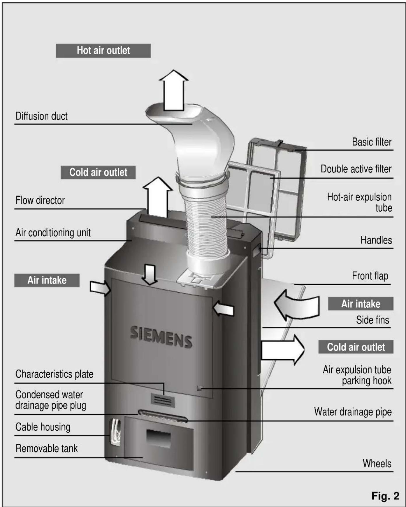
Description of the appliance
Your new appliance
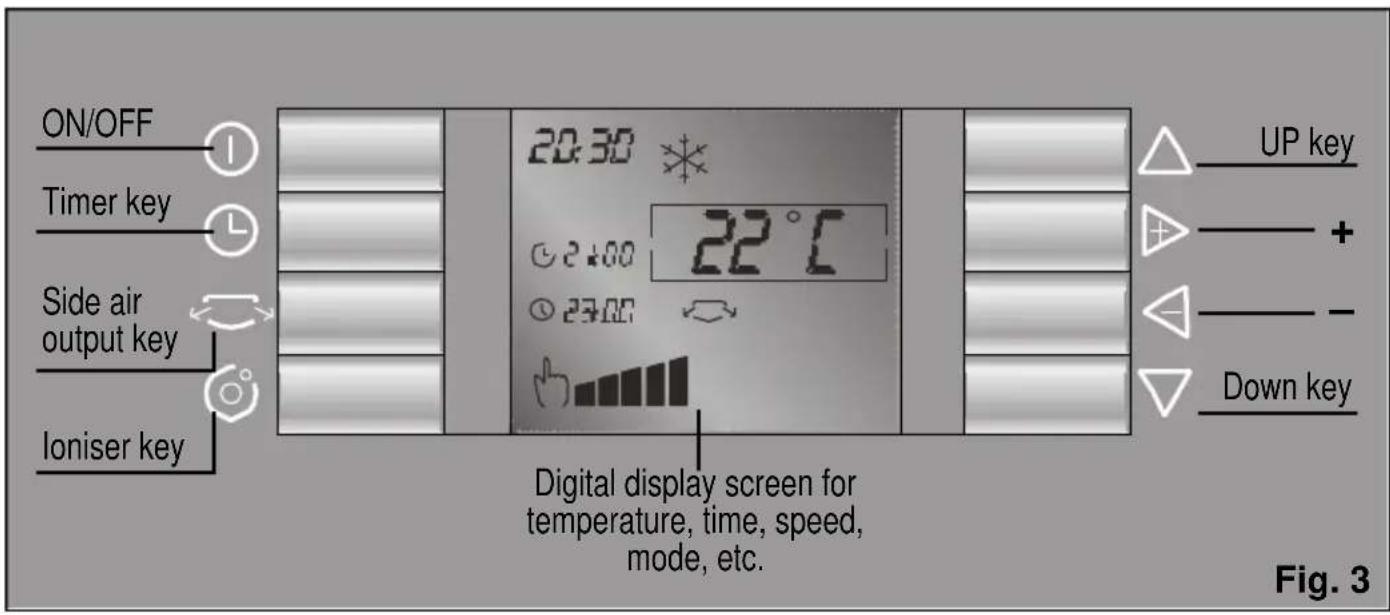
Control panel
Description of accessories
| Suction Base Double wall grommet Sliding pad filter active balcony | |||||
| PA0840M | √ | √ | √ / ● | ● | ★ |
| Approx. max. (length x width) cm. | ∅ wall 14 | 70 x 10205 x 10 | |||
√ Standard accessories: These accessories are supplied with the appliance.
- Optional accessories: These accessories are available for purchase from the manufacturer's official technical service and authorised distributors.
* Optional accessories: These accessories are only available for purchase from the manufacturer's official technical service.
Requirements for use
Requirements for use
☐ This home appliance should be connected to a 220/240 V, 50 Hz mains electricity supply via an earthed socket.
☐ It must be protected with a 10 A slow-action fuse.
☐ Should an extension lead be required, then this lead should be at least 1.5 mm² thick per terminal, less than 25 m long and earthed.
☐ There is a cavity at the back of the appliance to house the mains electricity supply cable. See Fig. 2.
☐ Do not allow water to enter your appliance and do not cover the air intakes/outlets.
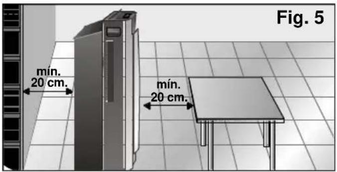
☐ For safety reasons, the appliance must be at least 20 cm away from any nearby surface before it is turned on, Fig. 5.
The mains electricity supply connection cable must only be replaced by authorised members of the manufacturer's Official Technical Service.
When the appliance is turned off and then turned back on, it takes the compressor 3 minutes to start up again. This period of time is required in order to ensure correct operation.
Avoid direct contact with the air expelled through the expulsion tube.
Navigation
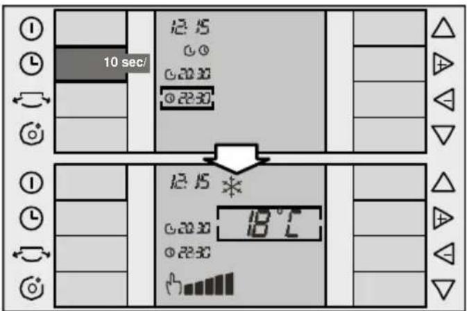
The control panel is designed to make it easier to use your appliance. The following points need to be taken into consideration.
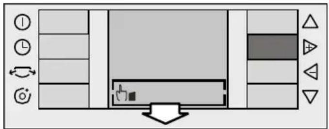
The "up" and "down" keys are used to move up and down the screen. The "+" and "-" keys (right and left) are used to move to the right and to the left in the selection box. The box shows the function selected for modification.
The following is an example of navigation:
Up and down keys
The "up" and "down" keys are used to move up and down the screen.
"Down" key ∨:
Starting from the screen shown in the first figure (the selection box is situated on the operation function option). If you press key ▽, the selection box moves down to the "Temperature selection" function.
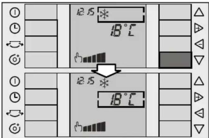
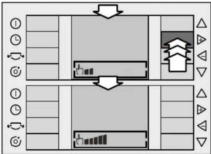
If you press key ∇ again, the selection box moves down to the "speed selection" function.
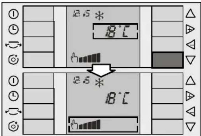
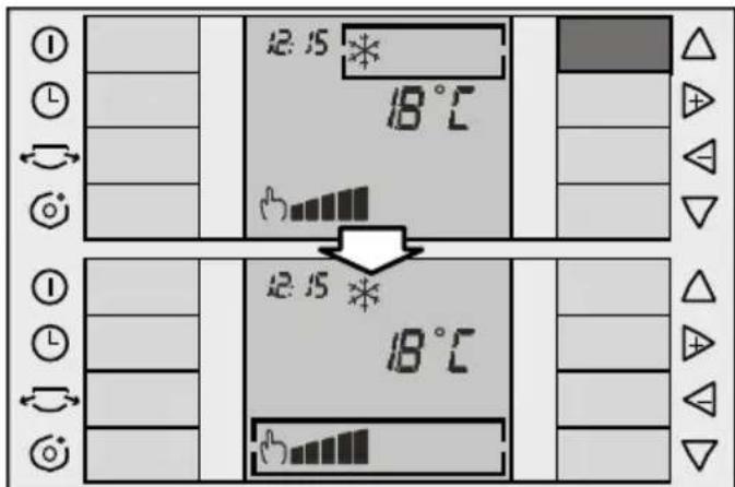
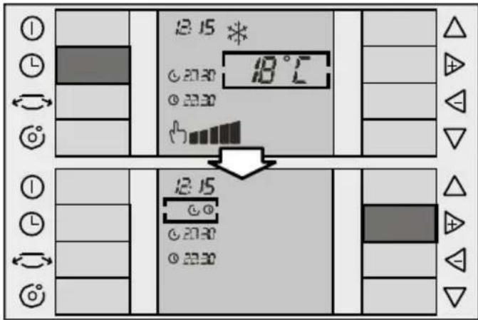
"Up" key △:
Key △works in exactly the same way as key ∨, the selection box moving up rather than down.
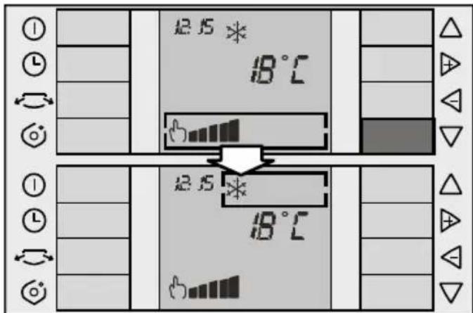
Cyclical operation:
Both keys work cyclically, i.e. if the selection box is at the bottom of the screen and key ∨ is pressed again, the selection box moves to the top of the screen. Likewise, if the selection box is at the top of the screen and key △ is pressed, the selection box moves to the bottom of the screen.
"+" and "-" keys
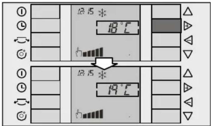
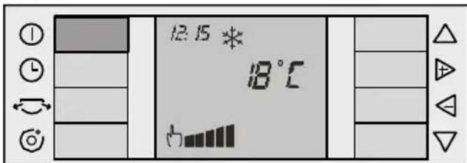
The "+" and "-" keys are used to move to the right and to the left within the selection box. If the function selected is temperature, these keys are used to increase ▶ and reduce ◀ the desired temperature as shown below:
Navigation
Instructions for Use
Preparing the appliance
Installing the air expulsion tube
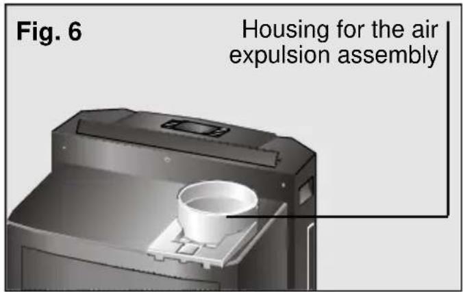
Fit the air expulsion tube onto the fixture with the "push" tab and thread it anti-clockwise, Fig. 6.
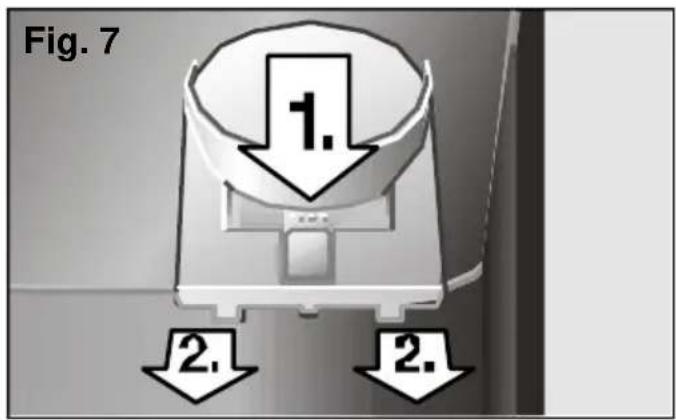
If easier, the housing can also be removed from the appliance by pressing the "Push" tab and sliding it out, Fig. 7.
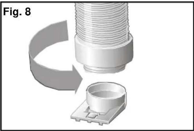
Once out, thread the expulsion tube as shown on Fig. 8, making sure that it is properly secured.
natural_image
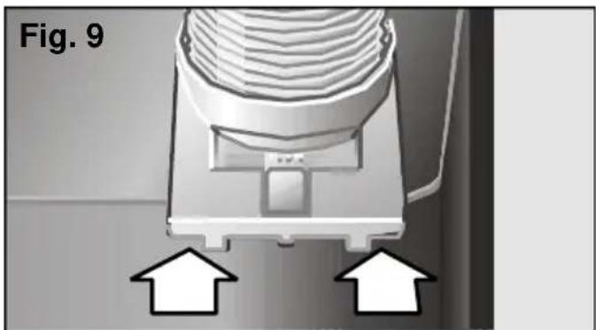
3D rendering of a mechanical component with threaded shaft and base, showing a curved arrow indicating rotation (no text or symbols)Then fit the assembly onto the appliance by slotting it into position Fig. 9.
natural_image
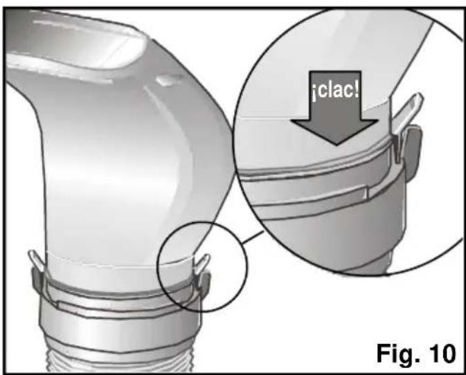
Close-up of a mechanical component with two white arrows pointing to features, labeled 'Fig. 9' (no readable text or symbols beyond label)Securing the diffusion duct onto the air expulsion tube
Fit the diffusion duct onto the free end of the tube pushing both parts gently until the duct clicks into place. Make sure that the clips are closed. Otherwise, the duct may fall off. Fig 10.
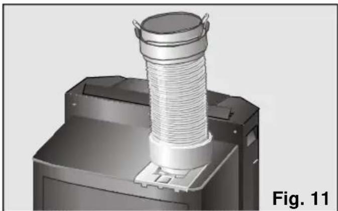
Installation for the dehumidification and air purification function
☐ Remove the diffusion duct and set the air expulsion tube to the position shown in fig. 11.
☐ The expulsion tube may also be totally dismantled if desired.
natural_image
3D rendering of a mechanical component with a coiled spring and mounting base, labeled Fig. 11 (no text or symbols on the object itself)Installing the air expulsion accessories for the air-conditioning function
There are a set of accessories used to expel hot air (see "Description of accessories").
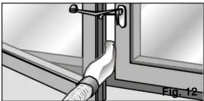
Installing the suction pad
☐ Open the window slightly and position the diffusion duct between the jamb and the glaze frame.
☐ Close the window as far as possible and secure it with the suction pad supplied, Fig. 12.
natural_image
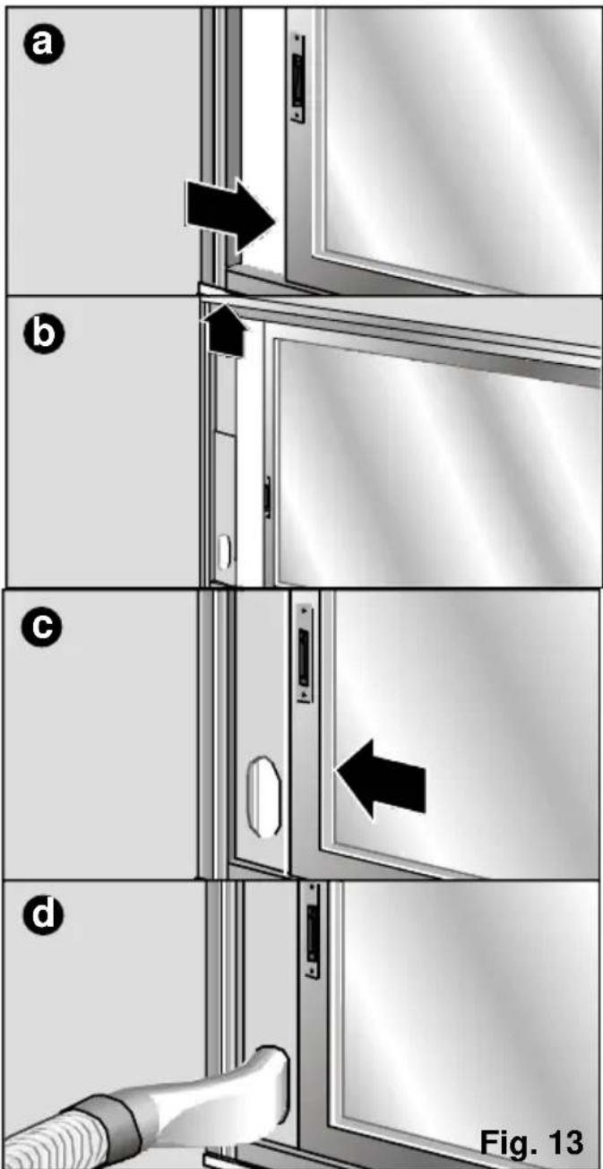
Illustration of a hand holding a flexible hose next to a window frame, labeled Fig. 12 (no text or symbols on the diagram itself)Installing the sliding window / balcony accessory
☐ The sliding window/balcony installation accessory supplied with your appliance can also be used (See "Description of accessories"), Fig. 13: a, b, c, d. This accessory can be used for both horizontal and vertical windows.
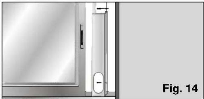
☐ The accessory has two holes on the side to fit it to the window / balcony with. The user can secure it to the frame or wall with two screws (not included with the accessory) to prevent it from moving or falling out of place, Fig. 14.
natural_image
Exterior view of a door with a door handle and an oval opening, labeled Fig. 14 (no text or symbols on the diagram itself)Permanent installation
Performed using the wall grommet accessory. See "Description of accessories".
☐ To expel hot air through the wall, it is necessary to make an 14-cm diameter hole in the wall and fit the wall grommet, Fig. 15.
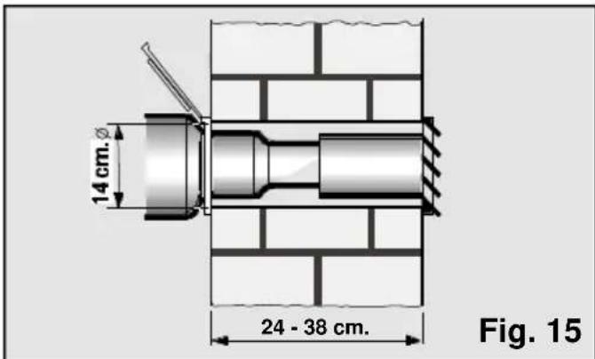
□ Remove the diffusion sleeve and connect the air expulsion tube to the accessory.
Notes
Do not extend the hot air expulsion tube more than necessary (maximum length; 140 cm).
Do not form sharp bends when positioning the tube, otherwise the correct expulsion of hot air may be impeded. This may cause a reduction in the cooling power and performance of the appliance.
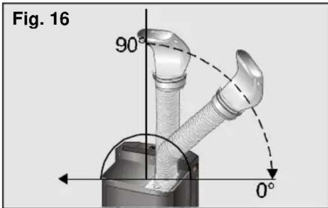
In order to achieve maximum cooling efficiency and minimum noise levels, the expulsion tube should be fitted above the total height of the appliance, Fig. 16.
Turning the appliance on and off
Press the "On" / "Off" key Ⓘ to start the appliance.
Warning!
Make sure that the appliance is plugged into the mains electricity supply.
Selecting the operation function
The following functions can be selected on your appliance:
□ cooling *.
□ dehumidification ^△ .
□ air purification
Place the selection box on the operation function menu using the "up" and "down" keys (see "Navigation": "up" and "down" keys).
Use the "+" and "-" keys to move within the selection box and select the desired function (see "Navigation": "+" and "-" keys).
Cooling
In this function, the appliance reduces ambient temperature until the desired temperature is reached. The appliance dehumidifies and purifies the air in the room at the same time in order to create a pleasant atmosphere.
Instructions for Use
□ Plug the appliance into the mains electricity supply.
☐ Lead the hot air expulsion tube outside, (see "Preparing the appliance before use").
☐ Check that the plug is fitted onto the water drainage pipe to prevent water from leaking onto the support surface.
□ Lift the air director on the top of the appliance, Fig. 17.
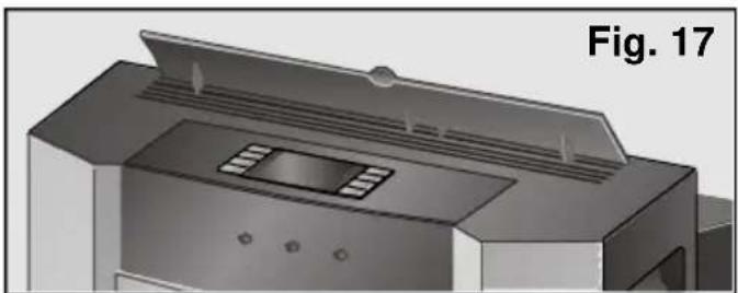
natural_image
3D rendering of a printer or printer with ventilation duct and mounting holes (no text or symbols visible)□ Turn the appliance on by pressing the "On" key ①.
□ Select the cooling function *, (see "Selecting the operation function").
☐ Select the desired temperature, (see "Selecting the temperature"). If the appliance turns itself off automatically because the desired temperature for the room has been reached, it will not start working again until ambient temperature rises 2-3°C.
□ Select the operation speed, (see "Selecting the speed").
During air conditioning, the condensed water produced evaporates automatically and is expelled outdoors together with the expelled air through the hot air expulsion tube.
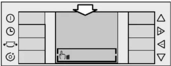
In conditions of extreme humidity, the appliance accumulates condensed water in the appliance's rear tank. When a certain level the appliance beeps twice. The removable tank full symbol □ appears on the screen at the same time to indicate that the tank needs to be emptied. The appliance stops working when this happens. To empty the removable tank, press the handle and remove the tank carefully. Empty the water down the nearest drain.
The symbol disappears from the screen when the water tank has been emptied and replaced on the appliance properly.
Warning!
When you turn the appliance back on again after emptying all of the water, do not forget to replace the removable tank on the appliance properly. Should you fail to do so, the symbol will not disappear from the screen and the appliance will not work.
Remember that when the appliance is turned off, it is necessary to wait for approximately 3 minutes before the compressor starts up again. This period of time is required in order to ensure correct appliance operation.
Dehumidification
In this operation function, the appliance reduces the humidity in the atmosphere. The appliance purifies the air in the room at the same time in order to create a pleasant atmosphere.
□ Plug the appliance into the mains electricity supply.
☐ Fit the hot air expulsion tube outside as indicated in "Preparing the appliance before use".
□ Lift the air director on the top of the appliance.
There are two ways of expelling condensed water: via the removable tank and in continuous mode.
Dehumidification via the removable tank:
- Check that the removable tank is fitted onto the appliance properly and that the plug is fitted onto the water drainage pipe to prevent water from leaking onto the support surface.
- When the water in the removable tank reaches a certain level, the appliance beeps twice. The removable tank full symbol □ appears on the screen at the same time to indicate that the tank needs to be emptied. The appliance stops working when this happens. The symbol also appears and the appliance beeps when the removable tank is not properly fitted into its housing.
• In both events, it is necessary to extract the tank and pour the water carefully down the nearest drain.
Dehumidification in continuous mode:
- Place a receptacle at the end of the water drainage pipe to collect the condensed water or lead the pipe to the nearest drain.
- Remove the plug from the water drainage pipe on the back at the bottom of the unit. The appliance does not stop working in this mode. It does not beep or display the symbol ☐ when the external receptacle is full.
- Select the dehumidification function (see "Selecting the operation function").
- Select the operation speed, (see "Selecting the speed").
Warnings
The amount of water dehumidified may vary depending on ambient conditions (See “Technical Information”).
When the appliance is operating in the dehumidification function, the temperature does not appear on the screen and cannot be selected or modified.
Warning!
Do not forget to replace the plug onto the water drainage pipe when you change function, otherwise the appliance will shed water when operated.
Remember that ambient temperature must be 18^ C or higher in order for the appliance to work.
The appliance expels hot air through the drainage pipe when operating in the dehumidification function. This is necessary for the appliance to work more efficiently in this operation function.
Air purification
The air inside the room (ventilation) is circulated through a purifying filter (air purification) when the appliance is set to this function.
The appliance comes with a basic filter (already fitted on the appliance) and a double active filter to be fitted by the user, see “Fitting the purifying filter (double active)”, against:
- Smells and smoke.
- Pollen, bacteria and dust.
□ Plug the appliance into the mains electricity supply.
☐ Fit the hot air expulsion tube (see "Preparing the appliance before use").
☐ Lift the air director on the top of the appliance.
□ Select the air purification function ⚙, (see "Selecting the operation function").
☐ Select the operation speed, (see "Selecting the speed").
Warning
We recommend you leave the filters in position regardless of the function setting (air conditioning, dehumidification, air purification) in order to purify the air more effectively.
Ionisation
Your air-conditioning system is fitted with an ioniser which can be connected additionally. The ioniser enriches the air with negatively charged ions. In nature, this normally happens after a summer storm, on the coast or in mountain areas. Ionised air is fresh and clean because it is exceptionally rich in negative ions
- Press the ioniser key Ⓞ on the control panel to activate the ioniser. The ion symbol appears on the screen and the appliance beeps to indicate that the function has been activated.
- Press the ioniser key again to deactivate it. The ioniser symbol disappears from the screen and the appliance beeps.
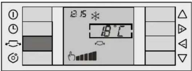
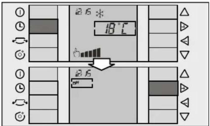
Selecting the temperature
This function is only available in the cooling function.
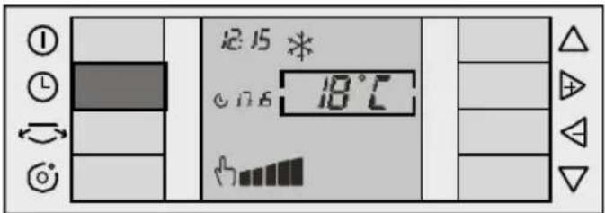
Place the selection box on the temperature selection menu (see "up" and "down" keys). Use the "+" and "-" keys to move within the selection box until the desired temperature is reached (see "+" and "-" keys).
The "+" key increases the desired temperature and the "-" key reduces the desired temperature.
The temperature selectable ranges from 18^ C to 30^ C and can be set to the nearest 1^ C. Keep the key pressed in to increase or decrease the desired temperature more quickly.
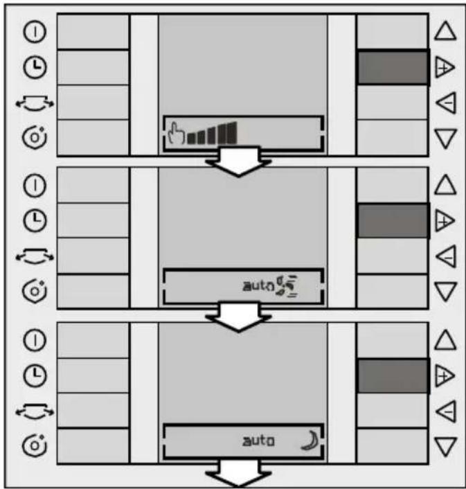
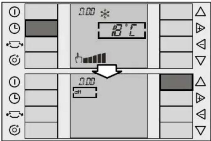
Selecting the speed
Your appliance has five manual speeds and two automatic speeds: maximum and silent. The maximum auto speed regulates the temperature by beginning at maximum cooling power until the temperature set by the user is reached. The silent auto speed regulates the temperature by beginning at a lower, more silent cooling power until the temperature set by the user is reached.
Manual speeds:
Place the selection box on the speed selection menu (see "Navigation" Up and down keys). Use the "+" and "-" keys to move within the menu to set the desired speed (see "Navigation" "+" and "-" keys).
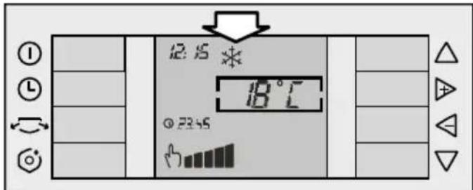
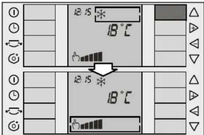
The manual symbol appears on the screen followed by the last speed set. Press the "+" and "-" keys to change the speed from maximum 🔊 to silent 🔊 and vice versa.
flowchart
graph TD
    A["Step 1: Clock"] --> B["Step 2: Refresh"]
    B --> C["Step 3: Feedback"]
    C --> D["Step 4: Reconciliation"]
    D --> E["End"]
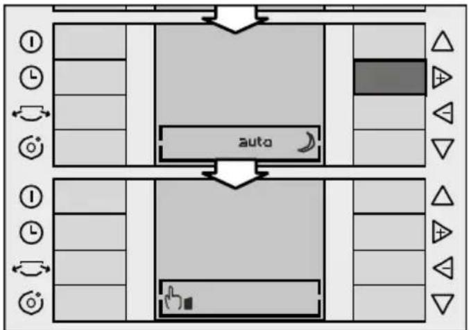
Automatic speeds:
Place the selection box on the "Speed selection" menu to activate this speed and press the "+" and "-" keys.
Once the maximum manual speed has been reached, press the "+" key again to move to the maximum auto speed. Press the "+" key again to access the silent auto speed. Press the "+" key again. The silent auto symbol disappears from the screen and the appliance works in manual mode again.
Press the "+" and "-" keys to deactivate automatic speed. The relevant auto symbol disappears and the appliance works at the manual speed set by the user once again.
flowchart
graph TD
    A["Left Lane"] --> B["Top Section"]
    B --> C["Bottom Section"]
    C --> D["Right Section"]
    D --> E["Left Lane"]
    style A fill:#f9f,stroke:#333
    style B fill:#ccf,stroke:#333
    style C fill:#cfc,stroke:#333
    style D fill:#fcc,stroke:#333
    style E fill:#ffc,stroke:#333
Instructions for Use
flowchart
graph TD
    A["Top Section"] --> B["Left Side"]
    B --> C["Right Side"]
    C --> D["Bottom Section"]
    D --> E["Left Side"]
    E --> F["Right Side"]
    F --> G["Bottom Section"]
    G --> H["Left Side"]
    H --> I["Right Side"]
    I --> J["Bottom Section"]
    J --> K["Left Side"]
    K --> L["Right Side"]
    L --> M["Bottom Section"]
    M --> N["Left Side"]
    N --> O["Right Side"]
    O --> P["Bottom Section"]
    P --> Q["Left Side"]
    Q --> R["Right Side"]
    R --> S["Bottom Section"]
Side fins
Your appliance is fitted with side fins which can be activated to distribute the air more efficiently.
Press the side fin key ↙ to open the fins and activate their operation. The relevant symbol ↙ is displayed on the screen.
Press the same key again to close the fins. The symbol disappears from the screen and the fins close.
These fins are available in all operation functions: cooling, dehumidification and air purification.
The side fins close automatically when the appliance is turned off via the "Off" key. If the side fins were open prior to turning the appliance off, they open again when the appliance is turned back on.
Setting the clock / Programming the timer
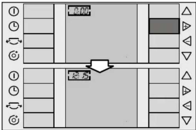
Setting the clock
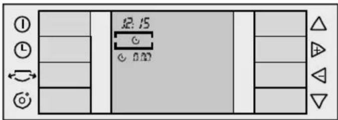
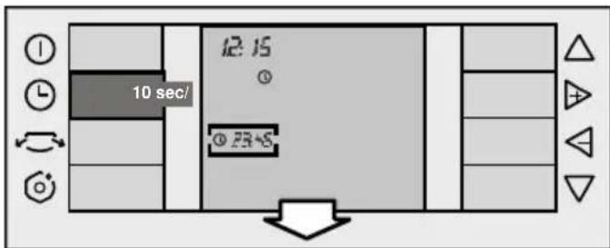
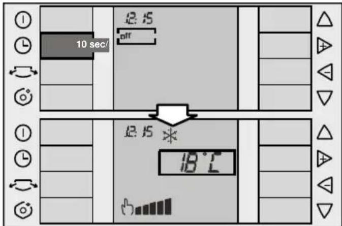
☐ The current time (24-hour clock) is displayed in the top left-hand corner of the screen the first time the appliance is connected to the mains electricity supply. 0:00 flashes by default.
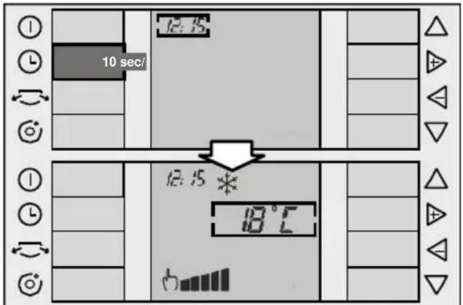
☐ To set the time, it is necessary to turn the appliance on by pressing the "On" key ①. If you take more than 10 seconds to perform the next operation during
programming / setting the clock on your appliance, the screen automatically returns to the main menu and the factory-set default settings are displayed or, if this is not the first time that the timer is set, the last settings used are displayed on the screen.
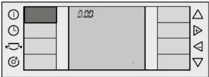
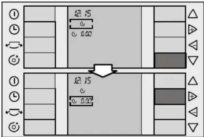
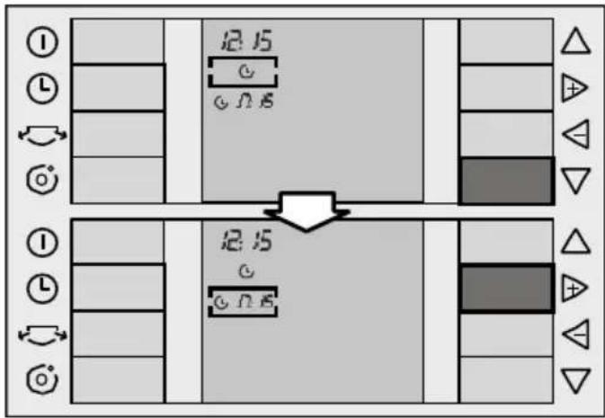
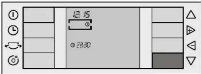
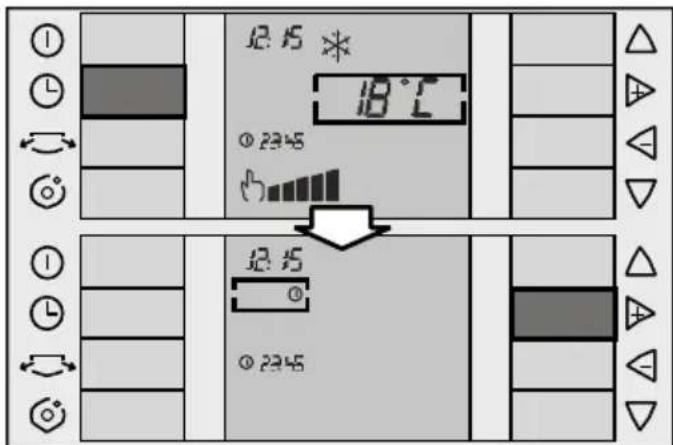
☐ Press the "Timer" key(L). The selection box appears on the timer menu with the last function selected ("Off" is displayed by default).
☐ Use the "up" key to place the selection box on the time. The time is modified using the "+" and "-" keys. The time increases or decreases by one minute each time one of these keys is pressed. Keep the key pressed in to increase or decrease the minutes more quickly.
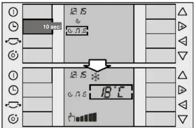
Instructions for Use
☐ Press the "Timer" key Ⓛ, to memorise the time. If you do not press this key, the time is automatically memorised when a period of 10 seconds has passed without pressing any key. The screen returns to the main menu.
Programming the timer
The appliance needs to be turned on with the clock set in order to programme the start / stop times.
Press the "Timer" key Ⓛ, to navigate through the timer menu. Press the "+" key to programme the different functions available on your appliance. These are:
- "Off" ①: appliance not programmed.
- "Start" programming the appliance start time.
- "Start/ Stop" programming the appliance start and stop time.
- "Stop" Ⓤ: programming the appliance.
Programming the appliance start time
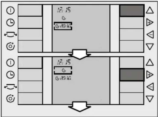
☐ Press the "Timer" key Ⓛ, to position the cursor on the timer menu. The last function programmed appears by default
□ Use the "+" and "-" keys to select the "Start" function ⏻, (see "+" and "-" keys).
☐ Use the "down" key (see "up" and "down" keys) to lower the cursor to the start time menu. Then use the "+" and "-" keys to modify the programmed time until the desired time is reached.
☐ The time changes 15 minutes at a time.
☐ Press the "Timer" key Ⓛ, or wait for 10 seconds without touching any keys to memorise the set start time.
☐ The set time is displayed on the screen together with the relevant symbol (the "Start" symbol ⏻) and the set functions.
Programming the appliance "Start" / "Stop" timer
☐ Press the "Timer" key, to position the cursor on the timer menu. The last function programmed appears by default.
□ Use the "+" and "-" keys to select the "Start" function ⏻, (see "+" and "-" keys).
☐ Use the "down" key (see "Up" and "down" keys) to lower the cursor to the start time menu. Then use the "+" and "-" keys to modify the programmed time until the desired time is reached.
☐ Press the "up" key again to position the cursor on the timer menu. Use the "+" and "-" keys to select the "Start" / "Stop" function. (see "+" and "-" keys).
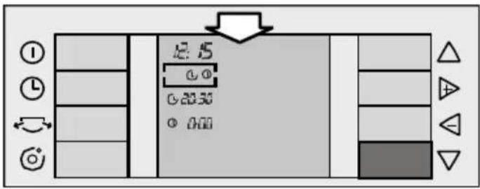
☐ Use the "down" key to position the cursor on the stop time menu. Then use the "+" and "-" keys to modify the stop time until the desired time is reached.
☐ The time changes 15 minutes at a time.
☐ Press the "Time" key, or wait for 10 seconds without touching any keys to memorise the set start / stop times.
☐ The set time is displayed on the screen.
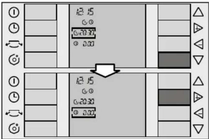
Programming the appliance stop time
☐ Press the "Timer" key Ⓛ, to position the cursor on the timer menu. The last function programmed appears by default.
Instructions for Use
□ Use the "+" and "-" keys to select the "Stop" function ⏻, (see "+" and "-" keys).
☐ Use the "down" key (see "up" and "down" keys) to lower the cursor to the stop time menu. Then use the "+" and "-" keys to modify the stop time until the desired time is reached.
☐ The time changes 15 minutes at a time.

☐ Press the "Timer" key(L), or wait for 10 seconds without touching any keys to memorise the set stop time.
☐ The set time is displayed on the screen.
Turning the timer off
☐ Press the "Timer" key(L), to position the cursor on the timer menu. The last function programmed appears by default.
□ Use the "+" and "-" keys to select the "Off" function.
☐ Press the "Timer" key(L), or wait for 10 seconds without touching any keys to turn the timer off. No set time is displayed on the screen.
☐ The times and functions set on the timer remain active and the programmed operation is repeated every day at the set times until deactivated or cancelled as described above.
Cleaning the appliance
☐ For safety reasons, you should unplug the appliance from the mains electricity supply before cleaning.
☐ The appliance can be cleaned with a cloth or sponge, slightly warm water and a mild detergent.
□ Never use hot water (more than 40°C), bleach, petrol, acid, scouring pads, brushes or strong detergents. Prevent water from entering the appliance.
☐ Do not clean the appliance with a water hose or compressed air.
Cleaning and changing the purifying filters
To change the purifying filter, it is first necessary to open the front flap on the appliance (it is not necessary to remove it). To do this, press the upper clip inside the door, Fig 18, and pull the flap. The flap can be opened up to the safety stop without risk of falling.
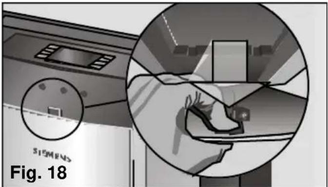
natural_image
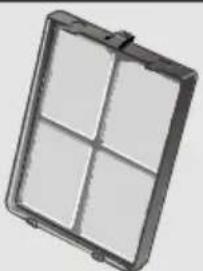
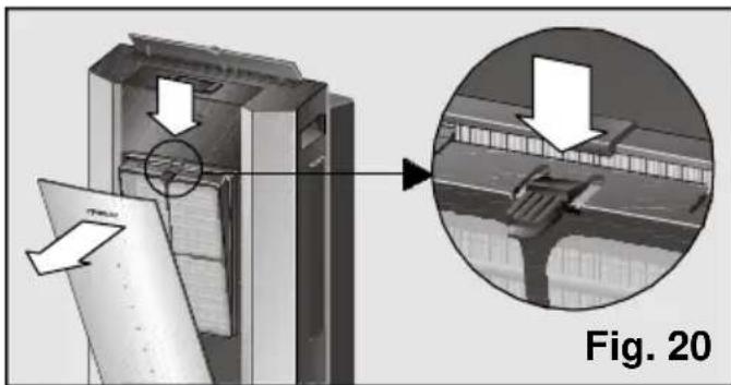
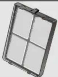
Interior view of a Siemens air conditioner unit with a close-up inset showing hand placement on the back panel (no text or symbols)All models are fitted with a basic filter which needs to be cleaned regularly, Fig. 19. The filter is accessed by pressing the tab at the top and removing it from its housing, Fig. 20. The filter is cleaned under a cold tap, dried and replaced.
Washable basic filter
natural_image
Exterior view of a rectangular metal enclosure with four square panes (no text or symbols)Fig. 19
Warning!
Do not try to clean the basic filter in a dishwasher. The plastic on the basic filter is not suitable for dishwashers and is unable to withstand the high temperatures involved in washing programmes. It will deform and may even break.
natural_image
Technical diagram showing a mechanical assembly with an inset close-up of a structural detail (no text or symbols present)These models also come with a purifying filter (double active) to be fitted by the user (See "Fitting the purifying filter").
The purifying filter further purifies the air in the room which passes through the appliance.
When the purifying filter is fitted, the appliance's cooling capacity may drop slightly. This is particularly the case when the filter is saturated or worn. It is, therefore, recommended that you check and change the filter at least once a year or when the "change filter" symbol is displayed. These accessories are available for purchase from the Manufacturer's Official Technical Service and authorised distributors (See "Description of accessories").
Press the "+" and the "-" key at the same time to make the symbol 📄 disappear from the screen after changing the filter. The symbol disappears from the screen and the filter is operational again.
Fitting the purifying filter (double active):
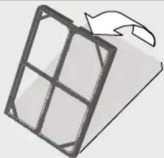
- Check that the purifying filter is fitted in the positioner. If it is not, fit as shown on Fig 21. Place the dark part of the filter in contact with the positioner.
Cleaning and Maintenance
natural_image
Simple line drawing of a folded paper or document with a hand holding an arrow (no text or symbols)Fig. 21
- Remove the basic filter from the appliance, Fig. 20.
- Insert the double active filter + positioner in the basic filter as shown on Fig. 22, remembering that it must be housed on the lower studs first.
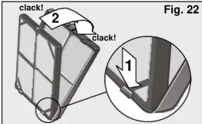
• Install the assembly onto the appliance by lining the lower studs up with the slots on the front casing of the appliance and pressing the top clip in until it clicks into position. The assembly is fitted properly when it clicks into position.
- Close the front flap.
Warning!
Fit only one set of filters onto the support in order to ensure correct appliance operation.
Note
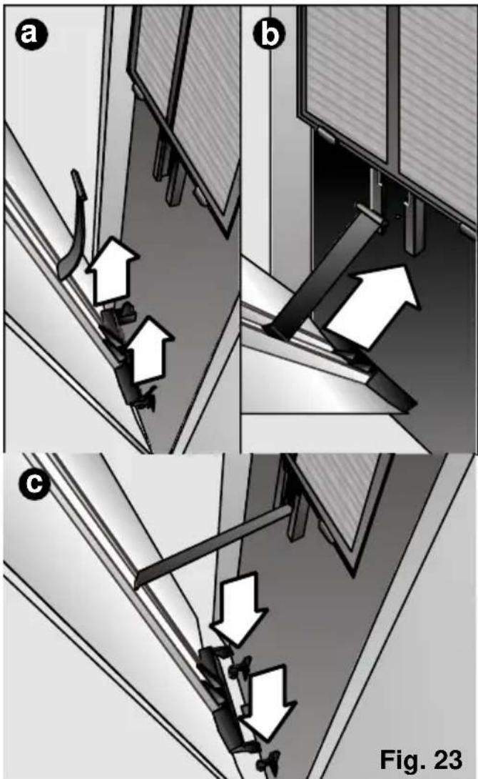
The flaps on these models are fitted with safety stops up to which point they can be opened without risk of the front flap falling and causing damage and/or injury. The front flap can also be removed in order to clean the appliance or change the filters more easily, see Fig. 18. Afterwards, or should for any reason the flap come out of its original housing, proceed as follows to fit it:
1° Lift the flap until it comes out of its lower supports, (Fig. 23: a).
2° Position the plastic leg in the front groove on the appliance (in T position) and slide it down to the safety stop, (Fig. 23: b).
3° fit the lower studs in the front stops on the appliance making sure that the plastic leg fitted in the previous step does not come out of position, (Fig. 23: c).
When finished, the user should make sure that the flap is fitted properly and does not fall when opened again. (The door opens up to the safety stop). If not fitted properly, repeat steps 1° and 2° again.
Cleaning and Maintenance
Transportation requirements
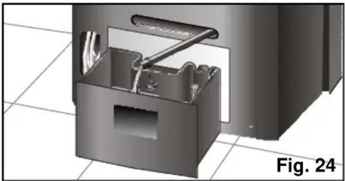
The appliance is fitted with wheels to make it easier to move around. It can be tilted, if necessary, in order to make transportation easier. You should not turn the appliance back on again for a minimum period of one hour after performing this procedure.
Before tilting it, empty the condensed water from the internal tank by extracting the water drainage pipe from its housing and removing the plug, Fig. 24. Place a receptacle (or the appliance's removable tank) at the end of the water drainage pipe to collect the condensed water or lead the pipe to the nearest drain. Do not forget to replace the plug and reinsert the pipe in its housing when the tank is empty.
natural_image
3D mechanical assembly diagram showing internal components and part alignment (no text or symbols)Storage requirements
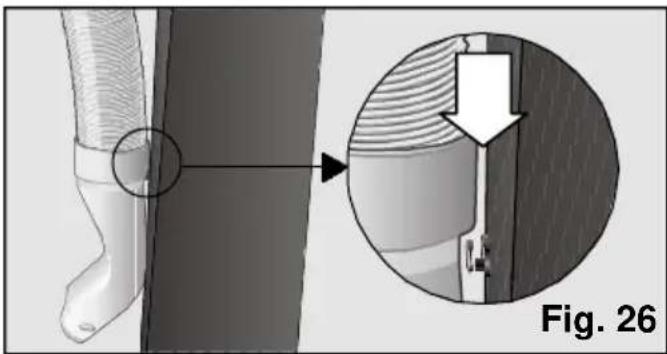
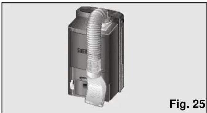
When the appliance is out of use for a long period, set the expulsion tube to parking position so that the appliance takes up as little space as possible.
☐ To do this, bend the tube towards the back of the appliance and secure it with the diffusion hook, Figs. 25 and 26.
natural_image
3D rendering of a Siemens air duct connector (no text or symbols visible)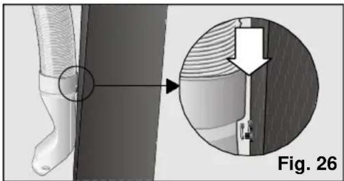
natural_image
Medical illustration showing a surgical procedure on a patient's foot, with magnified view of the procedure (no text or symbols present)Prior to use at change of season
□ Clean the air filter.
□ Clean the casing and the grilles if necessary.
Technical service / Warranty
Technical service
Should your appliance fail to work properly and all the instructions for use and installation (especially the section headed
"Requirements....") have been carefully observed, then remember that our Technical Service Network is at your full disposal.
When contacting the Technical Service, quote the model code (E-NR) and the appliance's factory number (FD). This information can be found on characteristics plate, Fig. 2.
Warranty
The conditions of warranty depend on the relevant Supplier in a particular country. Contact the establishment where you purchased your appliance for more information and quote the appliance model and factory number. The receipt of purchase for the appliance must be produced prior to any work carried out under warranty.
General requirements for operation
What to do if ...
... the appliance does not work ...
□ Check that it is plugged in properly.
☐ Check that the mains electricity supply is working. Check the fuse box.
☐ Set the thermostat to its minimum temperature position.
... the appliance does not work and the symbol indicating that the condensed water tank is full is displayed on the screen ...
☐ Set the appliance on a flat surface. If the symbol does not disappear, empty the water tank. Make sure that the tank is refitted properly afterwards. (See instructions in "Cooling").
... the appliance does not reduce room temperature sufficiently ...
☐ Check the joins on the hot air expulsion tube.
☐ Make sure that the expulsion tube is not too bent and that it is not extended to more than 140 cm.
□ Make sure that the plug is fitted on the drainage water pipe.
☐ Fit the suction pad to close the window as far as possible.
☐ Lower blinds to reduce direct sunlight.
... the fault symbol is displayed on the screen ...
□ Get in touch with an authorised dealer, customer service or the manufacturer's Technical Service Network.
... there is water on the control panel grille or on the basic filter housing ...
☐ There is no cause for concern. This is normal.
Noise
... the appliance makes a lot of noise ...
☐ Some noise is normal and other types of noise can be solved easily. You need to be able to distinguish between these types of noise:
Perfectly normal noise
☐ The sound of water flowing in cycles is due to the pump, which circulates the water to enhance the power of the appliance.
☐ A dull, humming sound is inevitable due to the compressor.
☐ A faint, whistling sound is due to the refrigerant passing through the thinner pipes on the appliance when the compressor starts up.
☐ A short clicking sound is produced when the pump connects and disconnects or when the regulator connects or disconnects the electronics system.
Easy-to-solve noises
□ Make sure that the air expulsion tube and the diffusion and collection sleeves are fitted properly onto the appliance.
□ Make sure that the air intakes and outlets on the appliance are free of obstacles.
□ Make sure that the appliance is not in direct contact with furniture or other appliances. The air output may be flowing directly onto these and thereby increasing the noise level.
Any other type of fault or repair work should be dealt with by a specialised Technician. Get in touch with your authorised dealer, customer service or the Technical Service Network.
Sommaire
natural_image
Symbol of a trash bin crossed with two diagonal lines, representing no waste or discharge (no text or labels)
natural_image
3D rendering of a mechanical device with a handle and internal components, labeled Fig. 1 (no text or symbols on the device itself)Touches "up" et "down"
Concept de navigation
Touches "+" et "-"
natural_image
3D rendering of a mechanical component with threaded shaft and base, showing a curved arrow indicating rotation (no text or symbols)natural_image
Close-up of a mechanical component with two white arrows pointing to features, labeled 'Fig. 9' (no text or symbols on the object itself)Mode d'Emploi
natural_image
3D rendering of a mechanical component with coiled spring and mounting base, labeled Fig. 11 (no text or symbols on the object itself)natural_image
Illustration of a hand holding a flexible hose to install a wall-mounted bracket (no text or symbols visible)natural_image
Exterior view of a door frame with a door and door, labeled Fig. 14 (no other text or symbols)Installation fixe
natural_image
3D rendering of a printer or printer with ventilation duct and ventilation slots (no text or symbols visible)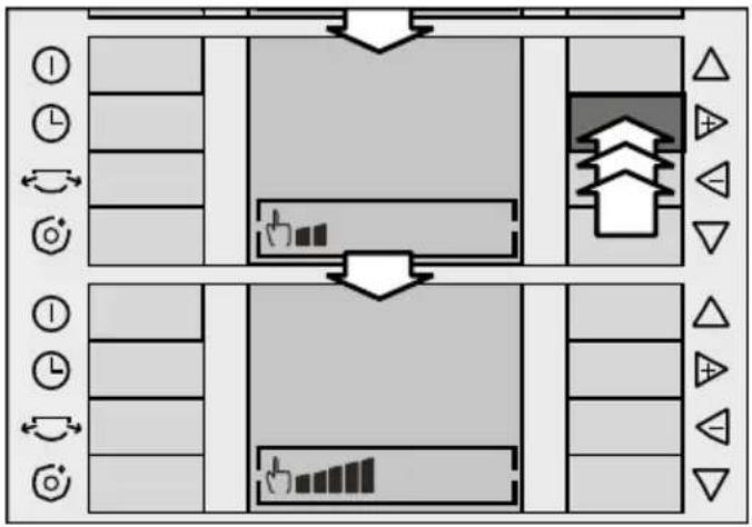
flowchart
graph TD
    A["Room 1"] --> B["Room 2"]
    B --> C["Room 3"]
    C --> D["Room 4"]
    D --> E["Room 5"]
    E --> F["Room 6"]
    F --> G["Room 7"]
    G --> H["Room 8"]
    H --> I["Room 9"]
    I --> J["Room 10"]
    style A fill:#f9f,stroke:#333
    style B fill:#ccf,stroke:#333
    style C fill:#cfc,stroke:#333
    style D fill:#fcc,stroke:#333
    style E fill:#cff,stroke:#333
    style F fill:#ffc,stroke:#333
    style G fill:#cfc,stroke:#333
    style H fill:#fcc,stroke:#333
    style I fill:#ffc,stroke:#333
flowchart
graph TD
    A["Top Lane"] --> B["Left Path"]
    B --> C["Right Path"]
    C --> D["Bottom Lane"]
    style A fill:#f9f,stroke:#333
    style D fill:#bbf,stroke:#333
    subgraph Left Path
        I1["Time Icon"] --> I2["Clock Icon"] --> I3["Light Bar Icon"] --> I4["Light Bar Icon"] --> I5["Light Bar Icon"] --> I6["Light Bar Icon"] --> I7["Light Bar Icon"] --> I8["Light Bar Icon"] --> I9["Light Bar Icon"] --> I10["Light Bar Icon"] --> I11["Light Bar Icon"] --> I12["Light Bar Icon"] --> I13["Light Bar Icon"] --> I14["Light Bar Icon"] --> I15["Light Bar Icon"] --> I16["Light Bar Icon"] --> I17["Light Bar Icon"] --> I18["Light Bar Icon"] --> I19["Light Bar Icon"] --> I20["Light Bar Icon"] --> I21["Light Bar Icon"] --> I22["Light Bar Icon"] --> I23["Light Bar Icon"] --> I24["Light Bar Icon"] --> I25["Light Bar Icon"] --> I26["Light Bar Icon"] --> I27["Light Bar Icon"] --> I28["Light Bar Icon"] --> I29["Light Bar Icon"] --> I30["Light Bar Icon"] --> I31["Light Bar Icon"] --> I32["Light Bar Icon"] --> I33["Light Bar Icon"] --> I34["Light Bar Icon"] --> I35["Light Bar Icon"] --> I36["Light Bar Icon"] --> I37["Light Bar Icon"] --> I38["Light Bar Icon"] --> I39["Light Bar Icon"] --> I40["Light Bar Icon"] --> I41["Light Bar Icon"] --> I42["Light Bar Icon"] --> I43["Light Bar Icon"] --> I44["Light Bar Icon"] --> I45["Light Bar Icon"] --> I46["Light Bar Icon"] --> I47["Light Bar Icon"] --> I48["Light Bar Icon"] --> I49["Light Bar Icon"] --> I50["Light Bar Icon"] --> I51["Light Bar Icon"] --> I52["Light Bar Icon"] --> I53["Light Bar Icon"] --> I54["Light Bar Icon"] --> I55["Light Bar Icon"] --> I56["Light Bar Icon"] --> I57["Light Bar Icon"] --> I58["Light Bar Icon"] --> I59["Light Bar Icon"] --> I60["Light Bar Icon"] --> I61["Light Bar Icon"] --> I62["Light Bar Icon"] --> I63["Light Bar Icon"] --> I64["Light Bar Icon"] --> I65["Light Bar Icon"] --> I66["Light Bar Icon"] --> I67["Light Bar Icon"] --> I68["Light Bar Icon"] --> I69["Light Bar Icon"] --> I70["Light Bar Icon"] --> I71["Light Bar Icon"] --> I72["Light Bar Icon"] --> I73["Light Bar Icon"] --> I74["Light Bar Icon"] --> I75["Light Bar Icon"] --> I76["Light Bar Icon"] --> I77["Light Bar Icon"] --> I78["Light Bar Icon"] --> I79["Light Bar Icon"] --> I80["Light Bar Icon"] --> I81["Light Bar Icon"] --> I82["Light Bar Icon"] --> I83["Light Bar Icon"] --> I84["Light Bar Icon"] --> I85["Light Bar Icon"] --> I86["Light Bar Icon"] --> I87["Light Bar Icon"] --> I88["Light Bar Icon"] --> I89["Light Bar Icon"] --> I90["Light Bar Icon"] --> I91["Light Bar Icon"] --> I92["Light Bar Icon"] --> I93["Light Bar Icon"] --> I94["Light Bar Icon"] --> I95["Light Bar Icon"] --> I96["Light Bar Icon"] --> I97["Light Bar Icon"] --> I98["Light Bar Icon"] --> I99["Light Bar Icon"] --> II00
    subgraph Right Path
        direction LR
        A1((I))
        A2((L))
        A3((C))
        A4((O))
        A5((S))
        A6((T))
        A7((W))
        A8((X))
        A9((Y))
        A10((Z))
        A11((A))
        A12((B))
        A13((C))
        A14((D))
        A15((E))
        A16((F))
        A17((G))
        A18((H))
        A19((I))
        A20((J))
        A21((K))
        A22((L))
        A23((M))
        A24((N))
        A25((O))
        A26((P))
        A27((Q))
        A28((R))
        A29((S))
        A30((T))
        A31((U))
        A32((V))
        A33((W))
        A34((X))
        A35((Y))
        A36((Z))
        A37((R))
        A38((S))
        A39((T))
        A40((U))
        A41((V))
        A42((W))
        A43((X))
        A44((Y))
        A45((Z))
        A46((O))
        A47((P))
        A48((Q))
        A49((R))
        A50((S))
        A51((U))
        A52((V))
        A53((W))
        A54((X))
        A55((Y))
        A56((Z))
        A57((O))
        A58((P))
        A59((Q))
        A60((R))
        A61((S))
        A62((U))
        A63((V))
        A64((W))
        A65((X))
        A66((Y))
        A67((Z))
        A68((O))
        A69((P))
        A70((Q))
        A71((R))
        A72((S))
        A73((U))
        A74((V))
        A75((W))
        A76((X))
        A77((Y))
        A78((Z))
        A79((O))
        A80((P))
        A81((Q))
        A82((S))
        A83((U))
        A84((V))
        A85((W))
        A86((X))
        A87((Y))
        A88((Z))
    end
    subgraph Right Path
        direction LR
    end
    classDef left stroke:#f0f,stroke-width:2px;
    class left of right: right;
    class right of left: right;
    class right of right: right;
    class left of right: left;
    class right of left: left;
    class right of right: left;
    class right of right: left;
    class right of right: left;
    class right of right: left;
    class right of right: left;
    class right of right: left;
    class right of right: left;
    class right of right: left;
    class right of right: left;
    class right of right: left;
    class right of right: left;
    class right of right: left;
    class right of right: left;

    class III stroke:#f0f,stroke-width:2px;
    class IV stroke:#f0f,stroke-width:2px;
    class V stroke:#f0f,stroke-width:2px;
    class VI stroke:#f0f,stroke-width:2px;
    class VII stroke:#f0f,stroke-width:2px;
    class VIII stroke:#f0f,stroke-width:2px;
    class X stroke:#f0f,stroke-width:2px;
    class Z stroke:#f0f,stroke-width:2px;
    class AA stroke:#f0f,stroke-width:2px;
    class AB stroke:#f0f,stroke-width:2px;
    class AC stroke:#f0f,stroke-width:2px;
    class AD stroke:#f0f,stroke-width:2px;
    class AE stroke:#f0f,stroke-width:2px;
    class AF stroke:#f0f,stroke-width:2px;
    class AG stroke:#f0f,stroke-width:2px;
    class AH stroke:#f0f,stroke-width:2px;
    class AI stroke:#f0f,stroke-width:2px;
    class AJ stroke:#f0f,stroke-width:2px;
    class AK stroke:#f0f,stroke-width:2px;
    class AL stroke:#f0f,stroke-width:2px;
    class AM stroke:#f0f,stroke-width:2px;
    class AN stroke:#f0f,stroke-width:2px;
    class AO stroke:#f0f,stroke-width:2px;
    class AP stroke:#f0f,stroke-width:2px;
    class AQ stroke:#f0f,stroke-width:2px;
    class AR stroke:#f0f,stroke-width:2px;
    class AS stroke:#f0f,stroke-width:2px;
    class AT stroke:#f0f,stroke-width:2px;
    class AU stroke:#f0f,stroke-width:2px;
    class AV stroke:#f0f,stroke-width:2px;
    class AW stroke:#f0f,stroke-width:2px;
    class AX stroke:#f0f,stroke-width:2px;
    class AY stroke:#f0f,stroke-width:2px;
    class AZ stroke:#f0f,stroke-width:2px;
    class BA stroke:#f0f,stroke-width:2px;
    class BB stroke:#f0f,stroke-width:2px;
    class BC stroke:#f0f,stroke-width:2px;
    class CD stroke:#f0f,stroke-width:2px;
    class EFE stroke:#f0f,stroke-width:2px;
    class FFO stroke:#f0f,stroke-width:2px;
    class GROE stroke:#f0f,stroke-width:2px;
    class HUSTE stroke:#f0f,stroke-width:2px;
    class IDBE stroke:#ff0,stroke-width:2px;
flowchart
graph TD
    A["Top Lane"] --> B["Left Path"]
    B --> C["Right Path"]
    C --> D["Bottom Lane"]
    D --> E["Left Path"]
    E --> F["Right Path"]
    style A fill:#f9f,stroke:#333
    style C fill:#ccf,stroke:#333
    style D fill:#cfc,stroke:#333
Ailettes latérales
natural_image
Interior view of a washing machine with a magnified inset showing hand cleaning (no text or symbols)natural_image
Exterior view of a rectangular metal enclosure with four compartments (no text or symbols)Fig. 19
Attention !!!
natural_image
Technical illustration of a mechanical assembly with an inset showing a detail view of a structural detail (no text or symbols present)natural_image
Simple line drawing of a folded paper or panel with a curved arrow indicating rotation (no text or symbols)Fig. 21
natural_image
Diagram showing two views (a and b) of a mechanical or architectural component with arrows indicating movement, no text or symbols present.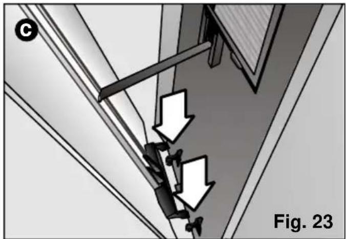
natural_image
Diagram showing a mechanical assembly with downward arrows indicating motion or force, labeled 'Fig. 23' (no text or symbols on the diagram itself)Conditions de transport
natural_image
3D mechanical assembly diagram showing internal components and a labeled section (Fig. 24), no readable text or symbols present.natural_image
3D rendering of a Siemens air duct assembly (no text or symbols visible)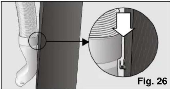
natural_image
Medical illustration showing a surgical procedure on a limb with an arrow indicating direction (no text or symbols present)natural_image
Symbol of a trash bin crossed with two crossed lines, representing no waste or discharge (no text or labels)
natural_image
3D rendering of a mechanical device with a handle and internal cavity, labeled Fig. 1 (no text or symbols on the device itself)Tecla "up" ^ :
natural_image
3D diagram showing a mechanical component with threaded shaft and base, no text or symbols presentnatural_image
Diagram of a mechanical component with two upward arrows indicating motion or force directions (no text or symbols)natural_image
3D rendering of a mechanical component with coiled spring and mounting base, labeled Fig. 11 (no text or symbols on the object itself)natural_image
Diagram of a hand holding a flexible hose to install a wall-mounted component, labeled Fig. 12 (no text or symbols on the diagram itself)natural_image
Diagram of a door with a vertical door and a horizontal door, labeled Fig. 14 (no text or symbols on the diagram itself)Instalación fija
natural_image
3D rendering of a printer or printer with ventilation ducts and mounting holes (no text or symbols visible)natural_image
Interior view of a car air conditioner unit with a magnified inset showing hand placement inside (no text or symbols)natural_image
Technical illustration of a mechanical device with an inset showing a close-up of a structural detail (no text or symbols present)natural_image
3D diagram of a mechanical component with a curved arrow indicating rotation, labeled Fig. 21 (no text or symbols on the diagram itself)natural_image
3D cutaway view of a mechanical device with internal components, labeled Fig. 24 (no text or symbols on the diagram itself)natural_image
3D rendering of a Siemens air purifier with coiled duct and control panel (no text or symbols visible)natural_image
Medical illustration showing a foot with a magnified inset of the internal structure, labeled Fig. 26 (no text or symbols on the diagram itself)natural_image
Symbol of a trash bin crossed with a diagonal line, representing no waste or discharge (no text or numbers present)
natural_image
3D mechanical component with a white arrow pointing to a slot, labeled Fig. 1 (no text or symbols on the object itself)Tecla "up" △:
natural_image
3D rendering of a mechanical component with threaded shaft and base, showing a curved arrow indicating rotation (no text or symbols)natural_image
Close-up of a mechanical component with two white arrows pointing to features, labeled 'Fig. 9' (no text or symbols on the object itself)natural_image
3D rendering of a mechanical component with coiled spring and mounting base, labeled Fig. 11 (no text or symbols on the object itself)natural_image
Illustration of a hand holding a flexible hose to install a window frame, labeled Fig. 12 (no text or symbols on the diagram itself)natural_image
Close-up of a hairless cable inserted into a door panel, labeled 'Fig. 13' (no other text or symbols visible)natural_image
Technical diagram showing a door frame with a side panel and a labeled section 'Fig. 14' (no text or symbols on the diagram itself)Instalação fixa
Atenção!
Certificar-se de que o equipamento está ligado à rede eléctrica.
natural_image
3D rendering of a printer or printer with ventilation ducts and a central screen (no text or symbols visible)natural_image
Interior view of a car air conditioner unit with a magnified inset showing hand placement inside (no text or symbols)natural_image
3D rendering of a rectangular plastic tray with four compartments (no text or symbols)Fig. 19
Atenção!!!
natural_image
Technical illustration of a mechanical assembly with an inset magnified view showing structural details (no text or symbols)natural_image
Simple line drawing of a folded paper or document with a paper feed and arrow indicating rotation (no text or symbols)Fig. 21
natural_image
3D mechanical assembly diagram showing internal components and a labeled section (Fig. 24), no readable text or symbols present.natural_image
3D rendering of a Siemens industrial device with coiled tubing and housing (no visible text or symbols)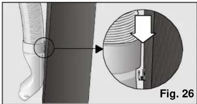
natural_image
Technical illustration of a mechanical component with cross-sectional view and magnified detail (no text or symbols)natural_image
Symbol of a trash bin crossed with two crossed lines (no text or numbers present)
natural_image
3D diagram of a mechanical device with a highlighted component and arrow, labeled Fig. 1 (no text or symbols on the device itself)natural_image
3D rendering of a mechanical component with threaded shaft and base, showing a curved arrow indicating rotation (no text or symbols)natural_image
Close-up of a mechanical component with two white arrows pointing upward, labeled 'Fig. 9' (no text or symbols on the object itself)Gebruiksaanwijzing
natural_image
3D rendering of a mechanical component with coiled spring and mounting base, labeled Fig. 11 (no text or symbols on the object itself)natural_image
Diagram of a hand holding a flexible hose to install a window frame, labeled Fig. 12 (no text or symbols on the diagram itself)natural_image
Exterior view of a door with a side panel and label 'Fig. 14' (no other text or symbols)Vaste installatie
natural_image
3D rendering of a printer or printer with ventilation duct and mounting holes (no text or symbols visible)natural_image
Interior view of a car air conditioner unit with a close-up inset showing hand placement on the backrest area (no text or symbols)Wasbare basis filter
natural_image
Exterior view of a rectangular metal enclosure with four compartments (no text or symbols)Fig. 19
Let op!!!
natural_image
Technical diagram showing a mechanical assembly with an inset magnified view of a building facade detail (no text or symbols present)natural_image
Simple line drawing of a folded paper or document with a paper feed and arrow (no text or symbols)Fig. 21
natural_image
Diagram showing two views (a and b) of a window with ventilation ducts and airflow arrows, no text or symbols present.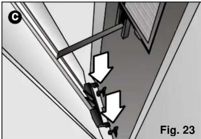
natural_image
Diagram showing a mechanical assembly with downward arrows indicating motion or force, labeled 'Fig. 23' (no text or symbols on the diagram itself)natural_image
3D mechanical assembly diagram showing internal components and a labeled section (Fig. 24), no readable text or symbols present.natural_image
3D rendering of a Siemens industrial control unit with coiled tubing and housing (no visible text or symbols)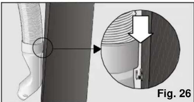
natural_image
Technical illustration of a mechanical component with cross-sectional view and magnified detail (no text or symbols)natural_image
Symbol of a trash bin crossed with no text or labels
natural_image
3D rendering of a kitchen oven with a white arrow pointing to a component, labeled 'Fig. 1' (no text or symbols on the main structure)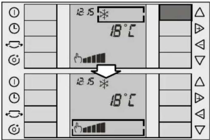
natural_image
3D rendering of a mechanical component with threaded shaft and base, showing a curved arrow indicating rotation (no text or symbols)natural_image
Diagram of a mechanical component with two upward-pointing arrows indicating motion or force, labeled 'Fig. 9' (no text or symbols on the diagram itself)Istruzioni d'uso
natural_image
3D rendering of a mechanical component with coiled spring and mounting base, labeled Fig. 11 (no text or symbols on the object itself)natural_image
Illustration of a hand holding a coiled cable next to a window frame, labeled Fig. 12 (no text or symbols on the diagram itself)natural_image
Exterior view of a door frame with a door and handle, labeled Fig. 14 (no other text or symbols)Installazione fissa
natural_image
3D rendering of a printer or printer with ventilation duct and fan (no text or symbols visible)natural_image
Interior view of a car air conditioner unit with a magnified inset showing hand placement inside (no text or symbols)natural_image
Exterior view of a rectangular metal enclosure with four internal compartments (no text or symbols)Fig. 19
natural_image
Technical illustration of a mechanical assembly with an inset magnified view showing structural details (no text or symbols)natural_image
Simple line drawing of a window frame with an arrow pointing to the top-right corner (no text or symbols)Fig. 21
natural_image
Diagram showing two mechanical assembly states (a and b) with arrows indicating motion direction, no text or symbols present.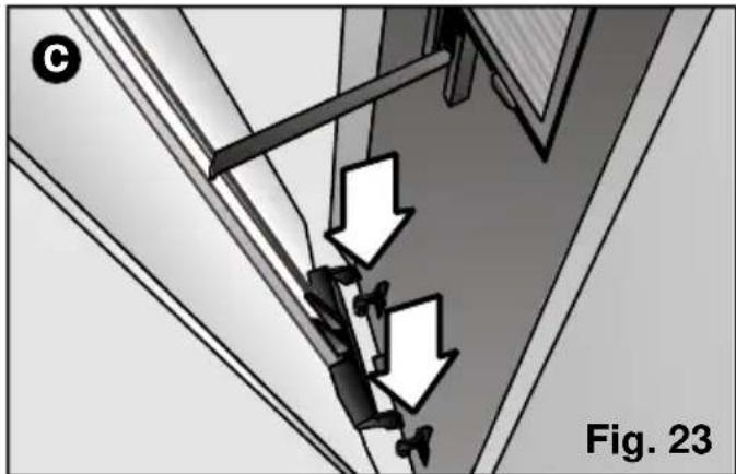
natural_image
Diagram showing a mechanical assembly with two downward arrows indicating motion or force, labeled 'Fig. 23' (no text or symbols on the diagram itself)natural_image
3D mechanical assembly diagram showing internal components and a labeled section (Fig. 24), no readable text or symbols present.natural_image
3D rendering of a mechanical device with coiled tubing and a labeled component (no readable text or symbols)Fig. 25