WVCM1430 - Surveillance Camera PANASONIC - Free user manual and instructions
Find the device manual for free WVCM1430 PANASONIC in PDF.
User questions about WVCM1430 PANASONIC
0 question about this device. Answer the ones you know or ask your own.
Ask a new question about this device
Download the instructions for your Surveillance Camera in PDF format for free! Find your manual WVCM1430 - PANASONIC and take your electronic device back in hand. On this page are published all the documents necessary for the use of your device. WVCM1430 by PANASONIC.
USER MANUAL WVCM1430 PANASONIC
Operating Instructions
Colour Video Monitor
WV-CM1430
Panasonic
Before attempting to connect or operate this product, please read these instructions completely
ENGLISH VERSION
We declare under our sole responsibility that the product to which this declaration relates is in conformity with the standards or other normative documents following the provisions of Directive EEC/89/336.
To ensure safe operation the three-pin plug supplied must be inserted only into a standard three-pin power point which is effectively earthed through the normal household wiring. Extension cords used with the equipment must be three-core and be correctly wired to provide connection to earth. Wrongly wired extension cords are a major cause of fatalities.
The fact that the equipment operates satisfactorily does not imply that the power point is earthed and that the installation is completely safe. For your safety, if in any doubt about the effective earthing of the power point, consult a qualified electrician.
CAUTION
RISK OF ELECTRIC SHOCK
DO NOT OPEN

CAUTION:
TO REDUCE THE RISK OF ELECTRIC SHOCK, DO NOT REMOVE COVER (OR BACK), NO USER SERVICEABLE PARTS INSIDE.
REFER SERVICING TO QUALIFIED SERVICE PERSONNEL.

The lightning flash with arrowhead symbol, within an equilateral triangle, is interned to alert the user to the presence of uninsulated "dangerous voltage" within the product's enclosure that may be of sufficient magnitude to constitute a risk of electric shock to persons.

The exclamation point within an equilateral triangle is intended to alert the user to the presence of important operating and maintenance (servicing) instructions in the literature accompanying the appliance.
The serial number of this product may be found on the bottom of the unit.
You should note the serial number of this unit in the space provided and retain this book as a permanent record of your purchase to aid identification in the event of theft.
Model No.
Serial No.
Vi erklzer es eneansvarlige for, at dette produkt, som denne deklaration omhandler, er i overensstemmelse med standarder ell erandre normative dokumenter i folge bestemmelserne i direktiv 89/336/EEC.
This appliance is supplied with a moulded three pin mains plug for your safety and convenience.
A 13 amp fuse is fitted in this plug.
Should the fuse need to be replaced please ensure that the replacement fuse has a rating of 13 amp and that it is approved by ASTA or BSI to BS1362.
Check for the ASTA mark or the BSI mark on the body of the
If the plug contains a removable fuse cover you must ensure that it is refitted when the fuse is replaced.
If you lose the fuse cover the plug must not be used until a replacement cover is obtained.
A replacement fuse cover can be purchased from your local Panasonic Dealer.
IF THE FITTED MOULDED PLUG IS UNSUITABLE FOR THE SOCKET OUTLET IN YOUR HOME THEN THE FUSE SHOULD BE REMOVED AND THE PLUG CUT OFF AND DISPOSED OF SAFELY. THERE IS A DANGER OF SEVERE ELECTRICAL SHOCK IF THE CUT OFF PLUG IS INSERTED INTO ANY 13 AMP SOCKET.
If a new plug is to be fitted please observe the wiring code as shown below.
If in any doubt please consult a qualified electrician.
WARNING: This apparatus must be earthed.
IMPORTANT
The wires in this mains lead are coloured in accordance with the following code.
Green-and-yellow: Earth
Blue: Neutral
Brown:Live
As the colours of the wire in the mains lead of this appliance may not correspond with the coloured markings identifying the terminals in your plug, proceed as follows.
The wire which is coloured green-and-yellow must be connected to the terminal in the plug which is marked with the letter E or by the earth symbol ± or coloured green or green-and-yellow.
The wire which is coloured blue must be connected to the terminal in the plug which is marked with the letter N or coloured black.
The wire which is coloured brown must be connected to the terminal in the plug which is marked with the letter L or coloured red.
How to replace the fuse
Open the fuse compartment with
a screwdriver and replace the fuse
and fuse cover.

WARNING:
TO PREVENT FIRE OR SHOCK HAZARD, DO NOT EXPOSE THIS APPLIANCE TO RAIN OR MOISTURE.
CONTENTS
PREFACE 1
FEATURES 1
PRECAUTIONS 1
MAJOR OPERATING CONTROLS AND THEIR FUNCTIONS 2
INSTALLATION 4
CABLE INFORMATION 4
SYSTEM CONNECTIONS 5
APPEARANCE 6
SPECIFICATIONS 6
OPTIONAL ACCESSORY 6
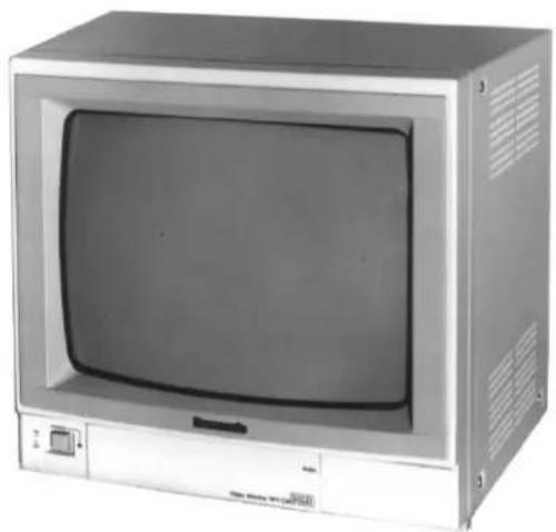
PREFACE
The WV-CM1430 is a colour monitor that ensure high-definition picture quality. All controls except for power are covered with a push door to give a sleek appearance on the front. The main controls of Colour, Brightness, and Contrast, are provided with sub controls to permit adjustment of preset levels. The ruggedly built metal cabinet is rack-mountable using optional bracket WV-Q104.
Standard BNC-type input and output connectors enables WV-CM1430 to be used with other CCTV monitors or Panasonic video tape recorder.
FEATURES
- 37 cm (14") diagonal CRT size
(Approx. 13" diagonal actual visual size) - Looping through BNC connectors for video input and output with 75 auto termination
- Looping through RCA pin jack for audio input and output.
Max. of 1.0W speaker output - Selectable of A or B channel for input and output signals.
- Rack mountable using optional Rack Angle Bracket.
PRECAUTIONS
- Do not block the ventilation slots.
- Do place the video monitor at least 5cm (2") apart from the wall.
- Do not expose the monitor to water or moisture.
- Do not operate the monitor if it becomes wet.
- Do take immediate action if ever the monitor becomes wet. Turn the power off and refer servicing to qualified service personnel. Moisture can damage the monitor and also create the danger of electric shock.
- Do not drop metallic parts in the slots. This action could permanently damage the monitor. Turn the power off immediately and refer servicing to qualified service personnel.
- Do not attempt to disassemble the monitor. In order to prevent electric shock, do not remove screws or cover. There are no user-serviceable parts inside. Refer servicing to qualified service personnel.
- Do not operate the monitor beyond its temperature, humidity or power source ratings.
Use the monitor under conditions where temperatures are within -10^ + 50^ (14°F - 122°F), and humidity is below 90% .
The input power source is 220 - 240V AC 50Hz.
The model numbers listed in this Operating Instructions have no suffixed attached to it.
MAJOR OPERATING CONTROLS AND THEIR FUNCTIONS
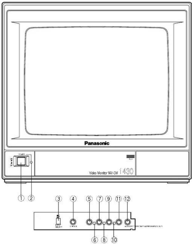
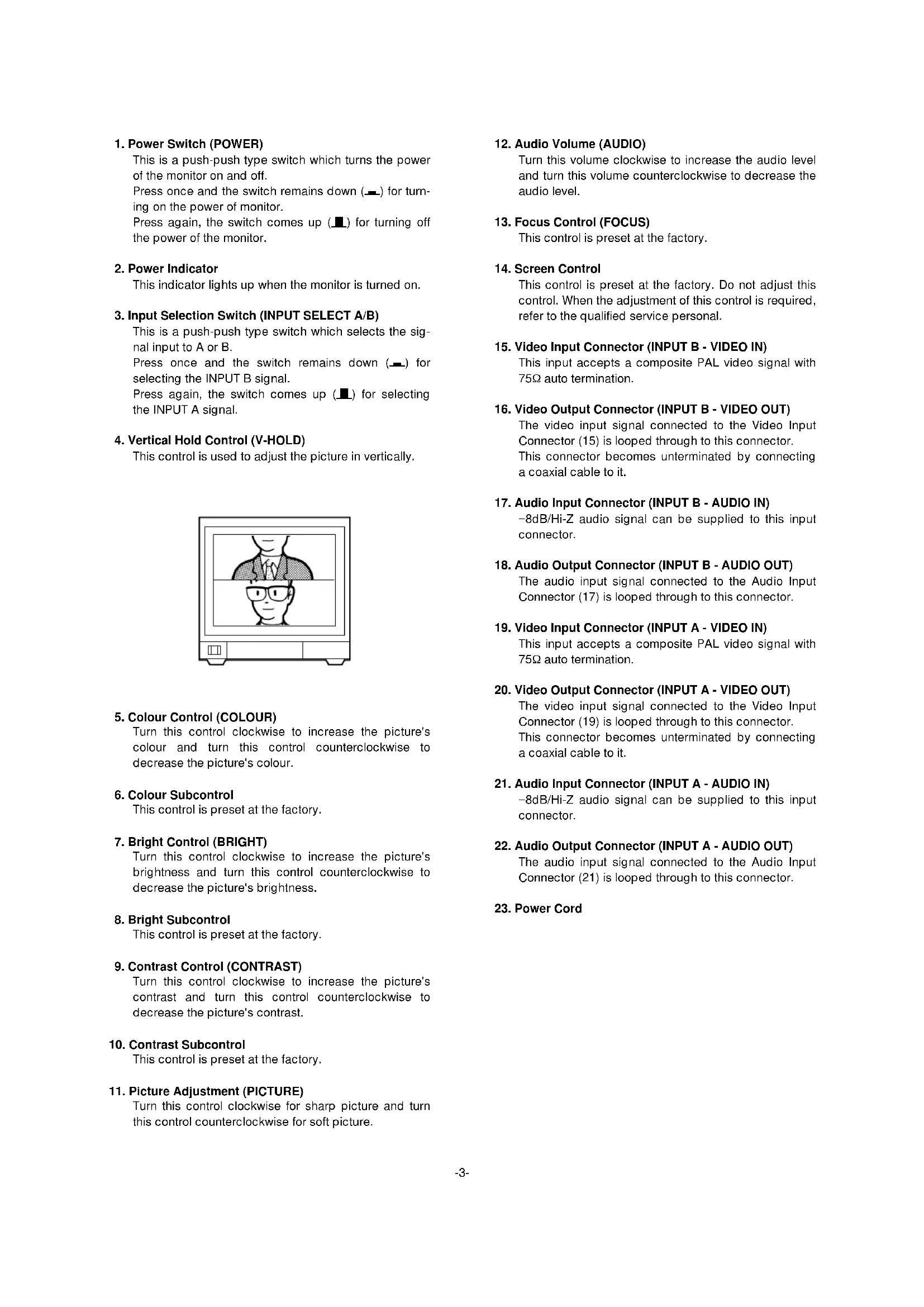
1. Power Switch (POWER)
This is a push-push type switch which turns the power of the monitor on and off.
Press once and the switch remains down ( ) for turning on the power of monitor.
Press again, the switch comes up (L) for turning off the power of the monitor.
2. Power Indicator
This indicator lights up when the monitor is turned on.
3. Input Selection Switch (INPUT SELECT A/B)
This is a push-push type switch which selects the signal input to A or B.
Press once and the switch remains down (■) for selecting the INPUT B signal.
Press again, the switch comes up (■) for selecting the INPUT A signal.
4. Vertical Hold Control (V-HOLD)
This control is used to adjust the picture in vertically.
5. Colour Control (COLOUR)
Turn this control clockwise to increase the picture's colour and turn this control counterclockwise to decrease the picture's colour.
6. Colour Subcontrol
This control is preset at the factory.
7. Bright Control (BRIGHT)
Turn this control clockwise to increase the picture's brightness and turn this control counterclockwise to decrease the picture's brightness.
8. Bright Subcontrol
This control is preset at the factory.
9. Contrast Control (CONTRAST)
Turn this control clockwise to increase the picture's contrast and turn this control counterclockwise to decrease the picture's contrast.
10. Contrast Subcontrol
This control is preset at the factory.
11. Picture Adjustment (PICTURE)
Turn this control clockwise for sharp picture and turn this control counterclockwise for soft picture.
12. Audio Volume (AUDIO)
Turn this volume clockwise to increase the audio level and turn this volume counterclockwise to decrease the audio level.
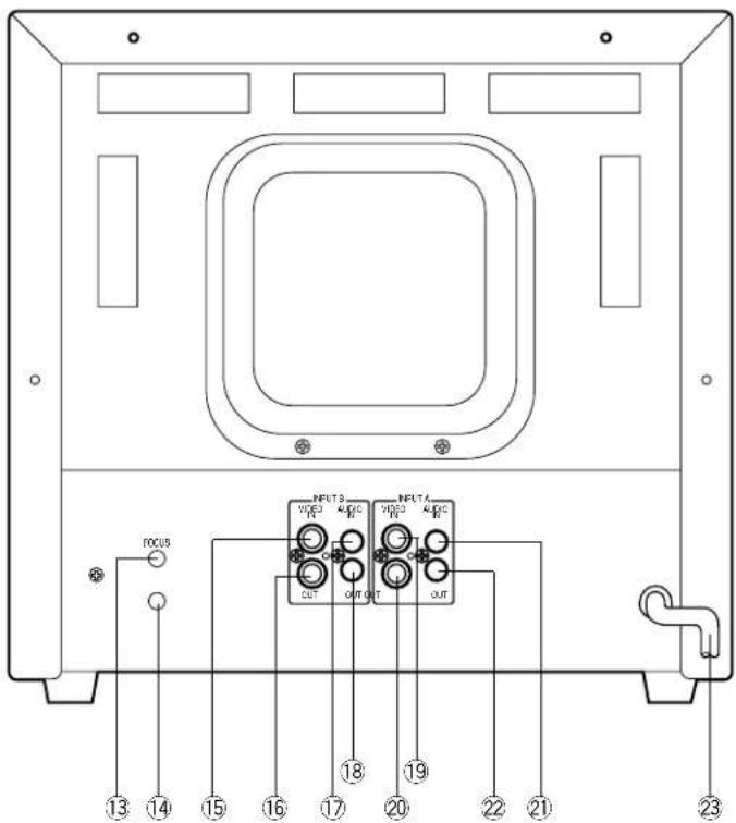
13. Focus Control (FOCUS)
This control is preset at the factory.
14. Screen Control
This control is preset at the factory. Do not adjust this control. When the adjustment of this control is required, refer to the qualified service personal.
15. Video Input Connector (INPUT B - VIDEO IN)
This input accepts a composite PAL video signal with 75 auto termination.
16. Video Output Connector (INPUT B -VIDEO OUT)
The video input signal connected to the Video Input Connector (15) is looped through to this connector. This connector becomes unterminated by connecting a coaxial cable to it.
17. Audio Input Connector (INPUT B - AUDIO IN)
-8dB/Hi-Z audio signal can be supplied to this input connector.
18. Audio Output Connector (INPUT B - AUDIO OUT)
The audio input signal connected to the Audio Input Connector (17) is looped through to this connector.
19. Video Input Connector (INPUT A - VIDEO IN)
This input accepts a composite PAL video signal with 75Ω auto termination.
20. Video Output Connector (INPUT A -VIDEO OUT)
The video input signal connected to the Video Input Connector (19) is looped through to this connector. This connector becomes unterminated by connecting a coaxial cable to it.
21. Audio Input Connector (INPUT A - AUDIO IN)
-8dB/Hi-Z audio signal can be supplied to this input connector.
22. Audio Output Connector (INPUT A - AUDIO OUT)
The audio input signal connected to the Audio Input Connector (21) is looped through to this connector.
23. Power Cord
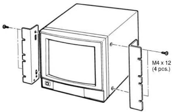
INSTALLATION
The Rack Angle Bracket WV-Q104 is provided for mounting the Colour Video Monitor WV-CM1430 on the standard 19" EIA rack.
(1) Remove four screws on both side of WV-CM1430. These screws are no use after this.
(2) Fix the Rack Angle Bracket by using the supplied four screws (M4 x 12).
(3) Mount the WV-CM1430 onto the rack by using the eight screws (local procurement).
Cautions
- Do not block the ventilation opening or slots on the cover to prevent the monitor from rising temperature. Always keep the temperature in the rack within 50^ (122^) .
- Secure the rear of the monitor to the rack by using the additional mounting angles (procured locally) when the vibration is added to the rack.
CABLE INFORMATION
Power Cable
- Keep the Power Switch (1) in the OFF position during installation.
- Connect the Power Cord to a grounded electrical outlet.
Video Cable
- Use 75-ohm coaxial cable. [RG-59/U (3C-2V), RG-6/U (5C-2V), RG-11/U (7C-2V), RG-15/U (10C-2V)]
-
Up to 10 monitors can be hooked up in this configuration before signal loss occurs. Total cable length should not exceed 150m (500 feet).
-
Wiring Precautions:
-
Do not bend coaxial cable into a curve whose radius is smaller than 10 times of its diameter:
- Never crush or pinch the cable.
All these will change the impedance of the cable and cause poor picture quality.
| Type of RG-59/U RG-6U coaxial cable (3C-2V) (5C-2V) (7C-2V) (10C-2V) | |||||
| Recommended (m) maximum cable length (ft) 825 | 250 | 500 | 600 800 | ||
| 25 | 1,65 | 1,980 2,640 | |||
SYSTEM CONNECTIONS
1. Single monitor Connection
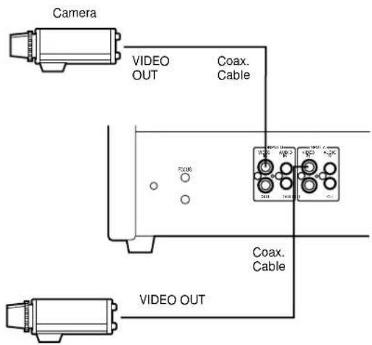
- Connect the Video Output terminal of the camera or VTR to the Video Input Connector (15) or (19) of the monitor with 75-ohm coaxial cable.
2. Multiple Monitor Connection
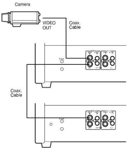
- Connect the Video Output terminal of the camera or VTR to the Video Input Connector (15) or (19) of the video monitor with 75-ohm coaxial cable.
- Connect the Video Output Connector (16) or (20) on the first monitor to the Video Input Connector (15) or (19) on the second monitor with 75-ohm coaxial cable, and continue until all monitors are connected.
Note: Properly check the connections in the input and output, because the monitor will not be properly terminated if the connections are wrong.
3. Audio circuit signal
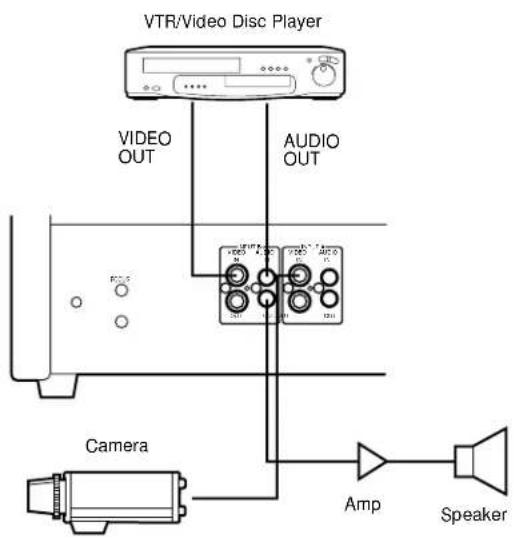
- Connect the Video Out Terminal of VTR or camera to the Video Input Connector (15) or (19) of this monitor with 75-ohm coaxial cable.
- Connect the Audio Out Terminal of VTR to the Audio Input Connector (17) or (21) of this monitor and connect the Audio Input Terminal of the audio amplifier to the Audio Output Connector (18) or (22) of this monitor with a audio cable.
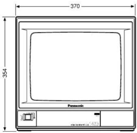
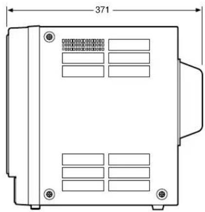
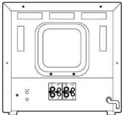
APPEARANCE
Unit: mm
SPECIFICATIONS
Power Source: WV-CM1430/A, WV-CM1430/B, WV-CM1430/G: 220 - 240V AC 50Hz
Power Consumption: Approx. 57 watts
Video Input/Output: 1.0 Vp-p composite/75Ω Auto Termination
Sweep Linearity: Less than 5%
Sweep Geometry: Less than 2%
Scanning Size: Approx. 8% (Overscanning)
CRT Size: 368.2 mm (14") diagonal
Actual Visual Size: 335.4 mm (13") diagonal
Audio Input/Output: -8dB/Hi-Z
Ambient Operating Temperature: -10^ + 50^ (14°F - 122°F)
Ambient Operating Humidity: Less than 90%
Dimensions: 370 (W) x 354 (H) x 371 (D) mm
Weight: 12.0kg
Weight and dimensions shown are approximate. Specifications are subject to change without notice.
OPTIONAL ACCESSORY
Rack Angle Bracket WV-Q104
DEUTSCHE AUSGABE
(GERMAN VERSION)
INHALT
Balayage: Suralayage (Environ 8%)
Dimensions: 370 (L) × 354 (H) × 371 (P) mm
Poids: 12 kg
ACCESSIONE OPTIONNEL
Matsushita Electric Industrial Co., Ltd.
Central P.O. Box 288, Osaka 530-91, Japan
N0495-1125 YWV8QA4034CN Printed in Japan