TCS 2500 - Mechanical chipper AL-KO - Free user manual and instructions
Find the device manual for free TCS 2500 AL-KO in PDF.

| Product type | Mechanical shredder (garden shredder) |
| Brand | AL-KO |
| Model | TCS 2500 |
| Power supply | 230 V ~ 50 Hz, rubber cable H05RN-F min. cross-section 1.5 mm², max. length 50 m |
| Maximum branch diameter | 40 mm (side opening) / 13 mm (top hopper) |
| Cutting type | Cutting disc with reversible blades and pre-cutter |
| Safety devices | Safety switch, overload protection switch, filling tube lock |
| Operation | Continuous with interruptions (40 s full load / 60 s idle) |
| Assembly | Leg frame, axle, wheels, hopper and filling tube (tools provided) |
| Intended use | Shredding of domestic and garden organic materials |
| Non-intended use | Prohibited for commercial, agricultural or forestry use, in rainy weather |
| Maintenance | Clean after use, replace blades in pairs, check screws |
| Cleaning | Brush or cloth, do not use water or pressure washer, spray anti-corrosion oil |
| Wear parts | Shredder blades, cutting disc, pre-cutter |
| Repairs | Entrust to AL-KO customer service or approved specialists |
| Warranty | Legal, wear parts excluded, repair or replacement as per choice |
| Storage | In a dry, closed place, out of reach of children, upright |
| Transport | Open the shredder in the middle, remove the tow bar and upper part |
| Provided accessories | 10 mm socket wrench, 10/8 mm open-end wrench, Torx T30 bit |
| Safety symbols on the device | Read the manual, keep hands/feet away, wear protective equipment, disconnect before maintenance |
Frequently Asked Questions - TCS 2500 AL-KO
User questions about TCS 2500 AL-KO
0 question about this device. Answer the ones you know or ask your own.
Ask a new question about this device
Download the instructions for your Mechanical chipper in PDF format for free! Find your manual TCS 2500 - AL-KO and take your electronic device back in hand. On this page are published all the documents necessary for the use of your device. TCS 2500 by AL-KO.
USER MANUAL TCS 2500 AL-KO
natural_image
Two identical black-and-white industrial sensors with labeled ports, shown from different angles (no text or symbols visible on the device itself)DE
GB
NL
FR
IT


Inhaltsverzeichnis
Deutsch 6
English....15
Nederlands 24
Français....33
Italiano 42
© 2021
AL-KO KOBER GROUP Kötz, Germany
This documentation or excerpts therefrom may not be reproduced or disclosed to third parties without the express permission of the AL-KO KOBER GROUP.
natural_image
Technical line drawing of a mechanical assembly with two bolts and a handle (no text or symbols)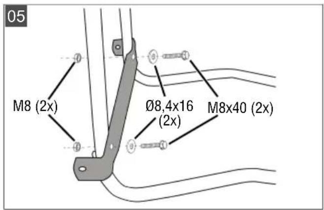
natural_image
Line drawing of a mechanical component with no visible text or symbols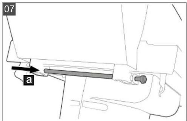
natural_image
Technical line drawing of a mechanical assembly with a central component and directional arrow (no text or symbols)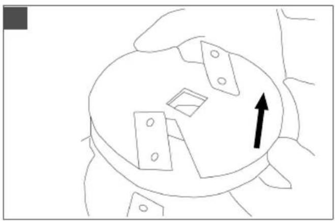
natural_image
Diagram of a mechanical component with a central circular feature and two rectangular components, no text or symbols present.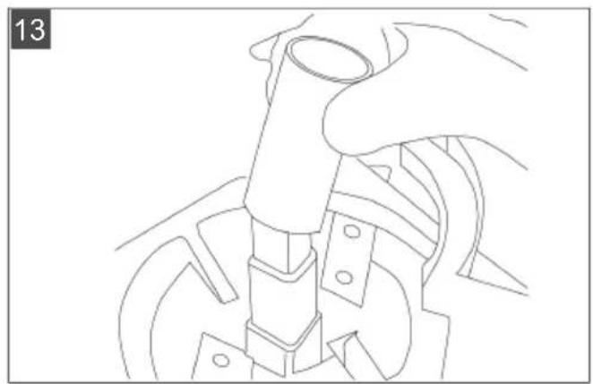
natural_image
Line drawing of a hand operating a mechanical device with no visible text or symbols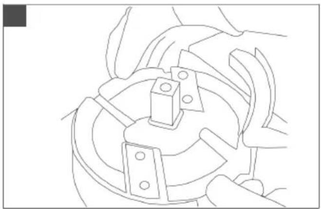
natural_image
Technical line drawing of a mechanical assembly with no visible text or symbols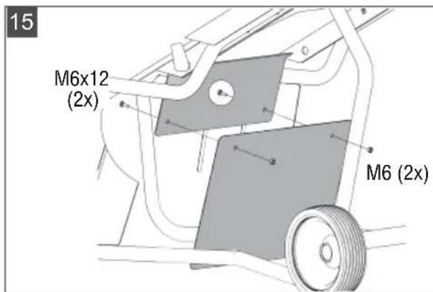
natural_image
Line drawing of a mechanical device with wheels and a chimney (no text or symbols)| TCS 2500TCS Duotec 2500 | TCS Duotec 3000 | |
 | TCS 2500: 119954TCS Duotec 2500: 119684 | 119685 |
 | 1415 x 966 x 655 mm 1415 x 966 x 655 mm | |
 | ca. 51 kg ca. 55 kg | |
 | 230 V AC / 50 HzGreat Britain: 240 V AC / 50 Hz | 400 V AC / 50 Hz |
 | 16 AGreat Britain: 13 A | 16 A |
 | 2790 min^-1 | 2830 min^-1 |
 | 2500 W (P40*) 2900 W (P40*) | |
 | max. 13 mm ∅ max. 13 mm ∅ | |
 | max. 40 mm ∅ max. 43 mm ∅ | |
 | L_wA = 113 dB(A) K = 2 dB(A) | L_wA = 113 dB(A) K = 2 dB(A) |
 | L_pA = 88 dB(A) K = 3 dB(A) | L_pA = 88 dB(A) K = 3 dB(A) |
* refer to section 3.1 for description of P40.
1 Special safety instructions .... 15
2 About these operating instructions ..... 15
2.1 Symbols on the title page.... 15
2.2 Legends and signal words ..... 16
3 Product description 16
3.1 Designated use 16
3.2 Possible foreseeable misuse .... 16
3.3 Residual risks...... 16
3.4 Safety and protective devices ..... 16
3.4.1 Safety circuit breaker.... 16
3.4.2 Switch with overload protection ... 16
3.5 Symbols on the machine...... 17
3.6 Electrical requirements.... 17
3.6.1 Mains connection.... 17
3.6.2 Mains cable 17
4 Safety instructions .... 18
5 Assembly 19
5.1 Enclosed tools.... 19
5.2 Assembling the base (01 - 04) ..... 19
5.3 Installing the axle and wheels (05 – 08)....19
5.4 Mounting the feed chute (09) ..... 20
5.5 Mounting the feed tube (09) 20
6 Operation 20
6.1 Connecting the mains plug.... 20
6.2 Switching on the motor.... 20
6.3 Feeding in material to be shredded.... 20
6.4 Switching off the motor.... 20
6.5 Releasing a cutting disk blockage..... 20
7 Maintenance and care 21
7.1 Shredder blade.... 21
7.2 Removing the feed tube 21
7.3 Exchanging/turning the shredder blades (10) 21
7.4 Dismantling the pre-cutter and cutting disc (10 - 13) ...... 21
7.5 Mounting the feed tube 22
7.6 Care....22
8 Storage.... 22
9 Help in case of malfunctions 22
10 Transport.... 22
11 Disposal.... 23
12 After-Sales / Service.... 23
13 Guarantee 23
1 SPECIAL SAFETY INSTRUCTIONS
This appliance can be used by children of 8 years and older and by persons with reduced physical, sensory or mental capabilities, or those lacking experience and knowledge, if they are supervised or have been instructed with regard to the safe use of the appliance and the ensuing risks. Children must not be allowed to play with the appliance. Cleaning and maintenance must not be carried out by children without supervision.
People with very strong and complex restrictions may have needs that exceed the instructions described here.
2 ABOUT THESE OPERATING INSTRUCTIONS
The German version is the original operating instructions. All additional language versions are translations of the original operating instructions.
■ Always safeguard these operating instructions so that they can be consulted if you need any information about the appliance.
■ Only pass on the appliance to other persons together with these operating instructions.
■ Comply with the safety and warning information in these operating instructions.
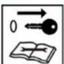
2.1 Symbols on the title page
Symbol Meaning

It is essential to read through these operating instructions carefully before start-up. This is essential for safe working and trouble-free handling.
Symbol Meaning

Operating instructions

To avoid electric shock, do not damage or cut the power cable!
2.2 Legends and signal words
⚠️ DANGER! Denotes an imminently dangerous situation which will result in fatal or serious injury if not avoided.
WARNING! Denotes a potentially dangerous situation which can result in fatal or serious injury if not avoided.
CAUTION! Denotes a potentially dangerous situation which can result in minor or moderate injury if not avoided.
IMPORTANT! Denotes a situation which can result in material damage if not avoided.
i NOTE Special instructions for ease of understanding and handling.
3 PRODUCT DESCRIPTION
3.1 Designated use
The garden shredder is only intended for use in shredding organic materials that are incurred in the home and garden. No other use is permitted. Only work with the trailer when it is fully assembled.
This trailer is intended solely for use in non-commercial applications. Any other use (as well as unauthorised conversions or add-ons) are regarded as contrary to the intended use and will result in exclusion of the warranty as well as loss of conformity (CE mark); the manufacturer will thus decline any responsibility for damage and/or injury suffered by the user or third parties.
P40: continuous operation with interruptions
The appliance can be operated continuously but with regular interruptions at high loads. If it is operated for too long at high loads, the overload protection switches the appliance off. The appliance has been tested and approved for operation at full load for 40 s followed by an idling time of 60 s.
3.2 Possible foreseeable misuse
■ The machine is not intended for commercial use or in agriculture and forestry.
■ Do not use the machine in rainy weather.
■ The safety devices on the machine must not be dismantled or bypassed.
3.3 Residual risks
Even during correct use of the appliance, there is always a certain residual risk that cannot be excluded. Depending on the use, the following potential risks can be derived from the type and construction of the appliance:
Injuries from flying cuttings
■ Injuries due to inhaling cutting particles
■ Injuries due to reaching into the shredder mechanism
■ Injuries due to the machine tipping over
3.4 Safety and protective devices
⚠ WARNING! Risk of injury. Defective and disabled safety and protective devices can result in serious injury.
■ Have any defective safety and protective devices repaired.
■ Never disable safety and protective devices.
3.4.1 Safety circuit breaker
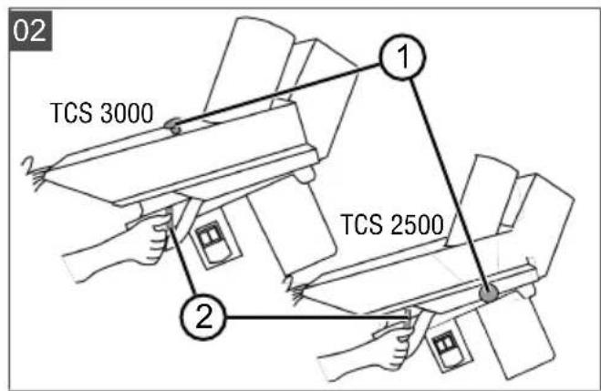
When the securing bolt (02/1) is pulled out, the safety circuit breaker is tripped. As a result, the motor can no longer be started by actuating the on/off switch.
The shredder can only be started with by actuating the on/off switch again when the feed tube has been fastened on the housing again using the original securing bolt.
3.4.2 Switch with overload protection
According to the VDE regulations, the appliance is equipped with a switch with an integrated safety switch that shuts off the current in the event of overloading. Overloading can occur if the blade is blocked for a long time.
For safety purposes, the safety switch is designed so that you have to wait for around 1 - 3 minutes before the motor can be switched on again. However, you must eliminate the cause of the overloading beforehand.
First, the switch must always be switched off in order to switch on the motor again. After the waiting time, the appliance can be started again by actuating the switch.
3.5 Symbols on the machine
Symbol Meaning

Pay special attention when handling this attachment!

Read the operating instructions before starting operation!
Keep hands and feet away from the shredder mechanism!
Do not reach into rotating parts.
Keep other people out of the danger area!
Maintain a safety distance!
Always disconnect the machine from the mains before maintenance or if the cable is damaged or cut.

Wear protective glasses and ear defenders.

Wear gloves.
3.6 Electrical requirements
3.6.1 Mains connection
⚠️ DANGER! Risk of electric shock if the log splitter is operated without residual current circuit breaker. Operation of the appliance without residual current circuit breaker in the mains connection can result in serious injuries or even death due to electric shock.
■ Before connecting the appliance, check whether the mains connection has a residual current circuit breaker for a maximum leakage current of 0.03 A.
If you cannot be sure that a residual current circuit breaker is installed: Use an additional portable residual current device with switched PE conductor.
■ Mains voltage, see "Technical data". Do not use any other mains voltage!
Only for Great Britain (240 V)!
This machine must be earth!
■ Never use a faulty power cable!
■ Check the power cable regularly for signs of wear and tear!
Wiring instructions:
When wiring the English 3 pin plug, please follow the instruction according to the colour coding as shown below:
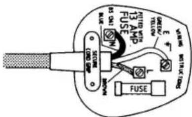
Green and yellow to terminal
E Earth
Brown to terminal
L Live
Blue to terminal
N Neutral
3.6.2 Mains cable
WARNING! Risk of injury from electric shock. A defective mains cable can result in serious injuries due to electric shock.
■ Make sure that the mains cable is not damaged or severed.
Use only rubber-sheathed cables of quality H05RN-F according to DIN 57282, Part 817 / VDE 0282, Part 817 with a rubber-coated plug connector and a conductor cross section of at least 1.5mm^2 (230 V: 3× 1.5mm^2 , 400 V: 5× 1.5mm^2 ). The cable must not be of a lighter type.
For the United Kingdom only: rubber-sheathed cables of type BS 6500 (1984), Table 16 PVC 3 core flex, 300/500 V HOS VV-F with a rubber-coated plug connector and a 13 A fuse.
The maximum permissible cable length is 50 m. A longer cable impairs the motor power and hence the performance and function of the log splitter.
■ Mains cable, mains plug and coupling socket must be undamaged. A defective mains cable (e.g. with cracks/fractures, cuts, crushed or kinked points in the insulation) must not be used.
- Check the condition of your mains cable each time prior to use.
■ Protect the mains cable from heat and sharp edges. Do not expose plug connectors to moisture.
- Do not pull on the mains cable to remove the mains plug from the socket.
If the mains cable is damaged, immediately disconnect it from the mains.
■ Repairs to the mains cable, mains plug and coupling socket may only be carried out by qualified electricians.
4 SAFETY INSTRUCTIONS
Operator:
■ Persons under the influence of alcohol, drugs or medication are not allowed to use the machine.
Personal protective equipment:
■ Wear clothing and protective equipment in accordance with the regulations in order to avoid injuries to the eyes, as well as to avoid hearing impairment.
The clothing must be appropriate (tightly fitting) and must not restrict movements. If you have long hair, it is essential to wear a hair net. The personal protective equipment comprises:
Ear protection
- Protective glasses
Work gloves
Safety shoes
Long trousers
Working area:
No further persons, children or animals may be in the working area of the shredder.
- Keep the working area free from material to be shredded and other objects – danger of stumbling.
The user of the machine is responsible for accidents involving other persons or their property.
■ Ensure good lighting of the working area.
Operating times:
■ When operating in residential areas, observe country-specific and communally permitted operating times according to the regulations on noise pollution.
■ Work with the machine in daylight or with good lighting only.
Operation:
- Do not reach into the hopper or feed chute during operation!
■ The cutting disk after-runs after the machine is switched off!
■ Only put the machine into operation when assembly has been completed.
■ Always perform a visible inspection prior to using the machine. The machine must be in a safe operating condition.
■ Never work alone. - Immediately renew damaged or worn parts.
■ Only use the machine if it is in the technical condition stipulated by the manufacturer.
Do not undertake shredding work in the rain, snow, stormy weather or during thunderstorms (danger of lightning!). Do not use the shredder in wet or damp surroundings. - Do not deactivate safety and/or protective devices on the machine.
■ Always ensure that the machine is stable before starting work.
■ Never transport the shredder with the motor running.
■ Never transport the shredder with open or unlocked shredder upper section.
■ Switch the motor off, wait for the cutting disk to stop moving, and disconnect the machine
from the mains connection prior to moving the machine.
- When moving the shredder, only transport it using its handle.
■ Always ensure a stable stance when working. Do not bend forward too far. - Do not feed the shredder from an elevated position.
■ Always disconnect the shredder from the mains power supply when not in use.
In the event of a malfunction or accident:
- Immediately disconnect the mains plug from the mains if the mains cable has been damaged or severed!
If a foreign object is drawn in or in the event of unusual noises or vibrations, immediately switch off the shredder and disconnect it from the mains. Then proceed as follows:
Inspect the damage.
■ Refasten loose parts, e.g. tighten screws.
- Have all damaged parts exchanged or repaired by our customer service.
5 ASSEMBLY
WARNING! Danger if assembly is not carried out completely! Use of an incompletely assembled device can result in serious injury.
■ Only use the device when it is fully assembled!
■ Before switching on, check that all safety and protective devices are in place and functioning correctly!
5.1 Enclosed tools
■ 1 socket wrench WAF 10
■ 1 open-end/ring spanner WAF 10/8
1 Torx bit T30
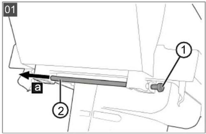
5.2 Assembling the base (01 - 04)
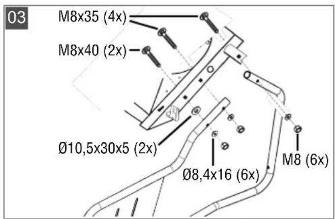
Accessories:
2 base tubes
■ 6 bolts M8 x 35/40 (TCS Duotec 2500: one of which is already mounted on the appliance)
■ 6 washers 8.4 x 16 - DIN 125
6 hexagon nuts M8
■ 2 washers 10.5 x 30 x 5
- Place the appliance on a suitable surface, e.g. a table.
-
Divide the shredder centrally.
-
Unscrew the nut M8 (01/1).
- Pull out (01/b) the pull rod (01/2) and remove the upper section.
- Release the securing bolt (02/1).
- Turn the central lock (02/2) and fold the feed tube away.
- Fold the lower section away sideways and remove the cardboard.
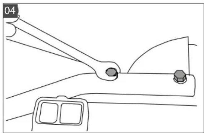
- Position the washers 10.5 x 30 x 5 and base tube on the housing and insert the screws M8 x 35/40 (3).
- Fix the base tube in position with the washers 8.4 x 16 (DIN 125) and nuts M8. (Assembly is identical on the left and right) (4).
i NOTE To simplify axle installation, do not tighten the nuts completely but only fix the base tubes in position using bolts.
5.3 Installing the axle and wheels (05 - 08)
Accessories:
1 axle tube
2 bolts M8x40
■ 2 washers diam. 8.4x16 - DIN 125
2 nuts M8
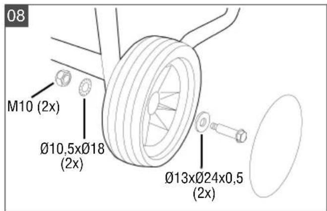
■ 2 wheels with ball bearings
■ 2 collar bolt (=axles)
■ 2 hexagon nuts M10
■ 2 corrugated washers 13x24x0.5
2 lock washers 10.5
-
Bolt (05) the axle tube to the feet using 2 bolts M8x40, 2 washers diam. 8.4x16 and 2 hexagon nuts M8.
-
Tighten the 6 nuts on the base tubes.
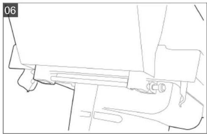
- Place the shredder lower section onto the feet.
- Place the shredder upper section onto the shredder lower section (06).
- Engage the shredder upper section in the central lock.
- Insert the pull rod through the holes in the shredder upper section and lower section (07).
- Screw a nut M8 onto the pull rod (07).
- Screw in the securing bolt (02/1).
- Fasten the wheels (with pressed-in ball bearings) to the axle tube with a collar bolt, 2 corrugated washers 13x24x0.5, 2 serrated washers 10.5 and a nut M10 (08).
- Mount the wheel covers on the wheels (08).
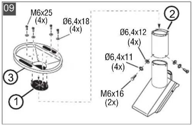
5.4 Mounting the feed chute (09)
Accessories:
1 screwdriver
4 bolts M6 x 25
■ 4 washers A6.4 DIN 9021
- Mount the safety flap (09/1) on the feed tube (09/2).
- Position the feed chute (09/3) on the feed tube.
- Fasten the feed chute on the feed tube using 4 bolts M6x25 and 4 washers diam. 6.4x18.
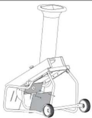
5.5 Mounting the feed tube (09)
Accessories:
■ 4 washers 6.4 - DIN 125
■ 4 serrated washers 6.4
1 bolt M6x25
3 bolts M6x16
- Position the feed tube (09/2) on the garden shredder.
- Fasten the feed tube on the garden shredder.
6 OPERATION
WARNING! Danger of serious injury!
There is a risk of serious injuries for children, persons with impaired physical, sensory or mental abilities, persons with insufficient knowledge and experience and persons who are not familiar with the operating instructions.
■ Never permit the above persons to use the machine.
■ Always observe the local regulations concerning the age limit for users.
6.1 Connecting the mains plug
- Connect the mains cable of the shredder to an extension lead.
- Check that the extension lead is connected securely.
- Then connect the extension lead to the mains voltage.
6.2 Switching on the motor
IMPORTANT! Damage to the machine due to improper operation! Incorrect handling can result in machine damage!
■ Only feed in material to be shredded once the appliance has already been switched on.
- Do not feed in any further material to be shredded after the appliance has been switched off.
- Press the on switch.
6.3 Feeding in material to be shredded
Material to be shredded includes e.g.:
Twigs, branches, shrubs, leaves
■ Flower stems, salad and vegetable waste
■ Paper, cardboard, etc. Remove metal staples from cardboard!
The following are not permissible, e.g.:
■ Roots of any kind mixed with soil and stones (damage to the blade).
■ Plastics, plastic bags, glass, metal parts
■ Bones, wood from fruit boxes, fabric waste, etc.
■ Newspapers, magazines, colour prints, mail order catalogues, etc. Such printed items contain plastic additives that do not rot.
Garden waste containing lots of seeds is unsuitable for composting.
Upper chute
The following are fed in from above:
Twigs, branches, shrubs up to max. 13 mm diam.
■ Vegetable and flower waste, paper, cardboard
Paper and cardboard: not folded too tightly; insert dry into the chute.
Feeding-in from the side
The following are fed in from the side:
All wood up to max. 40 mm diam. The smaller twigs at the end of the branch are then fed in from above again.
If the blades are sharpened well, the material to be shredded is pulled in with great force. Thicker branches therefore have to be held forcefully to prevent the motor from overloading.
6.4 Switching off the motor
- Press the off switch.
6.5 Releasing a cutting disk blockage
WARNING! Risk of injury due to lack of concentration while working! Ejected parts can cause very severe injuries!
■ Watch out for flying parts and keep your face away from the feed chute.
CAUTION! Danger of crushing when opening and closing the housing! Hand and finger injuries may occur!
■ Beware of your hands and fingers when opening and closing the housing.
i NOTE When closing the housing, ensure that the top part of the housing is correctly seated in the cutouts of the lower part.
- Switch off the shredder.
- Disconnect the machine from the mains power supply.
- Unscrew the locking screw and remove the housing.
- Remove the material causing the blockage.
- Check the cutting disk and shredder blade for damage.
- Close the housing and tighten the locking screw again.
- Reconnect the machine to the mains power supply.
- Press the overload protection switch.
- Switch on the shredder again.
If the blockage cannot be cleared, contact our customer service.
7 MAINTENANCE AND CARE
DANGER! Fatal electric shock hazard!
Touching live parts poses an immediate risk of fatal injury due to electric shock.
■ Disconnect the appliance from the mains prior to all maintenance, care and cleaning work.
WARNING! Danger of lacerations. Danger of cutting injuries when reaching into sharp-edged, moving appliance parts and into cutting tools.
■ Before maintenance, care and cleaning work, always switch off the appliance. Disconnect the appliance from the mains power supply.
■ Always wear protective gloves during maintenance, care and cleaning work.
WARNING! Risk of injury during repair work. Improper repairs can lead to serious injuries and damage to the appliance.
■ Have repair work performed by the manufacturer's service centres and authorised specialist companies only!
■ After each use, check the shredder for wear and renew any damaged components.
- Keep venting slots free of remnants and accumulations.
■ Only use spare parts specified by the manufacturer.
7.1 Shredder blade
To obtain an optimum shredding result and prevent damage to the machine, the blades must be replaced at regular intervals.
■ Always replace the blades in pairs.
■ Always tighten the bolts securely.
■ Do not work with blunt blades.
7.2 Removing the feed tube
- Switch off the appliance.
- Wait for the cutting disc to come to a standstill.
- Disconnect the mains plug.
- Loosen and remove the securing bolt (02/1). Danger! The securing bolt must not be replaced with any other bolt. Use only the original securing bolt!
- Turn the central lock (02/2) and fold the feed tube away.
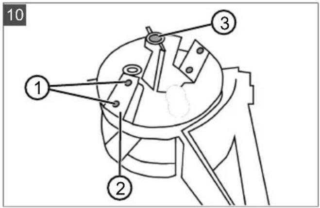
7.3 Exchanging/turning the shredder blades (10)
- Use the Torx bit T30 and open-end/ring spanner WAF 10/8 to loosen and remove the countersunk head screws (10/1).
- Remove and turn blade (10/2). Exchange the blade if both sides are blunt.
- Fasten the blade again and turn or exchange the second blade.
- Close the housing and tighten the securing bolt.
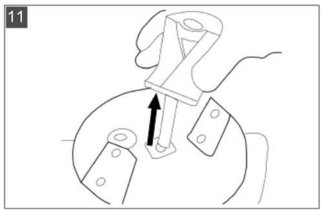
7.4 Dismantling the pre-cutter and cutting disc (10 - 13)
- Use the Allen key to release the Allen screw in the blade holder and hold the lower cutting disc to prevent it from turning (10).
- Remove the following parts upwards:
■ Allen key with pre-cutter (11) and washer
■ Upper cutting disc (12)
■ Spacer tube (13)
■ Lower cutting disc
Assemble in reverse order.
7.5 Mounting the feed tube
If the feed tube cannot be closed (jamming):
- Turn the cutting disc 90°.
-
Fold the feed tube back and engage in the securing lever (central lock).
Danger! Before starting, check that the feed tube is engaged! The feed tube must be engaged in the central lock. -
Screw in the securing bolt.
Danger! The securing bolt must not be replaced with any other bolt. Use only the original securing bolt!
7.6 Care
■ Remove dirt and material residues after every use.
- Do not clean the machine with running water or high-pressure.
■ Do not use any cleaning agents or solvents.
■ Use a soft brush or cloth for cleaning.
■ To protect the inner side of the housing from corrosion, spray it with a biologically degradable oil.
8 STORAGE
Clean the shredder after its use. Store it in a dry, lockable place out of the reach of children.
Perform the following tasks when storing during the winter period:
- Switch off the machine and disconnect it from the mains power supply.
- Wait for the cutting disk to come to a standstill.
- Unscrew the locking screw and remove the housing.
- Remove coarse and wet material from the inside of the shredder.
- Close the housing and tighten the locking screw.
- Store the shredder upright.
9 HELP IN CASE OF MALFUNCTIONS
NOTE For malfunctions that are not listed in this table or that you cannot resolve yourself, please contact our customer service.
| Malfunction Possible cause Solution | ||
| Motor does not start. Mains | socket (house installation) defective. | Use a different mains socket in the house. |
| Extension lead defective. Inspect the lead and replace it, if necessary. | ||
| Machine does not pull in material to be shredded. | Obstruction at the cutting unit. Remove material from the cutting unit, if necessary. | |
| Cutting unit clogged with wet material to be shredded. | Clear the clogging by feeding branch material. | |
| Material to be shredded is not properly cut. | Blades blunt or damaged Turn or replace the blades. | |
| Motor switches off. Motor | protection switch switched off due to cutting disk overload or blockage. | The motor can be switched on again after a cool-down phase of approx. five minutes. |
| Unusual noises, rattling in the machine. | Bolts on the motor, its mounting, the carriage or the cutting unit are loose. | Re-tighten bolts. |
10 TRANSPORT
To transport it more easily, the shredder can be separated in the centre (hinges).
- Unscrew the nut M8 (01/1).
- Pull out (01/b) the pull rod (01/2) and remove the upper section.
11 DISPOSAL
Information on the German Electrical and Electronic Equipment Act (ElectroG)

■ Electrical and electronic appliances do not belong in household waste, but should be collected and disposed of separately.
- Owners or users of electrical and electronic appliances are obliged by law to return them after use.
The symbol of the crossed-through rubbish bin means that electrical and electronic appliances may not be disposed of in the household rubbish. Electrical and electronic appliances can be handed in at the following places at no charge:
■ Public service disposal or collection points (e.g. municipal building yards)
■ Points of sale of electrical appliances (stationary and online) provided traders are obliged to take them back or offer this voluntarily.
These statements only apply to appliances that are installed and sold in the countries of the European Union and are subject to European Directive 2012/19/EU. Different provisions may apply to the disposal of electrical and electronic appliances in countries outside the European Union.
12 AFTER-SALES / SERVICE
In the event of questions of warranty, repair or spare parts, please contact your nearest AL-KO Service Centre. These can be found on the Internet at:
www.al-ko.com/service-contacts
13 GUARANTEE
We will resolve any material or manufacturing faults on the appliance during the legal warranty period for claims relating to faults, in accordance with our choice either to repair or replace. The legal warranty period is determined by the legislation of the country in which the appliance was purchased.
Our warranty promise applies only if:
■ These operating instructions are heeded
■ The appliance is handled correctly
■ Original spare parts have been used
The warranty becomes void in the case of:
■ Unauthorised repair attempts
■ Unauthorised technical modifications
Non-intended use
The guarantee excludes:
■ Paint damage that can be attributed to normal wear and tear
■ Wear parts that are marked with a frame xxxxxx (x) on the spare parts card
The guarantee period commences with purchase by the first end user. The date on the proof of purchase is decisive. In the event of a guarantee claim, please take this guarantee declaration and the original proof of purchase, and contact your dealer or the nearest authorised customer service centre. This statement does not affect the purchaser's statutory claims for defects against the vendor.
VERTALING VAN DE ORIGINELE GEBRUIKERSHANDLEIDING
Inhoudsopgave
3 PRODUCTOMSCHRIJVING
3.1 Beoogd gebruik
www.al-ko.com/service-contacts
13 GARANTIE
www.al-ko.com/service-contacts