
Sineax B811 - Industrial power supply Camille Bauer - Free user manual and instructions
Find the device manual for free Sineax B811 Camille Bauer in PDF.
| Product type | Industrial power supply for 2-wire converter |
| Brand | Camille Bauer |
| Model | Sineax B811 |
| Dimensions (housing S17) | Approx. 120 x 120 x 75 mm |
| Weight | Approx. 0.5 kg |
| Auxiliary supply | 24 ... 60 V DC/AC or 85 ... 230 V DC/AC depending on version |
| Power consumption | Approx. 2.5 W or ≤ 3 VA |
| Measurement outputs | A1 and A12: 0...5 V, 1...5 V, 0...10 V, 2...10 V or 0...20 mA, 4...20 mA configurable |
| Measuring loop and power supply (MSK) | Input 4...20 mA, supply voltage 24 V or 16.9 V/16.4 V depending on version |
| Communication | FSK (HART or specific protocol) on A1 or A12 |
| Loop monitoring | Break detection (<3.6 mA) and short-circuit (>21 mA) with AF relay and red LED |
| Accuracy | ≤ ±0.2% (including linearity and repeatability) |
| Response time | Approx. 200 ms |
| Operating temperature | -25 to +55 °C (standard); -20 to +55 °C (Ex) |
| Storage temperature | -40 to +70 °C |
| Relative humidity | ≤ 75% (standard); ≤ 95% (enhanced class) |
| Max. altitude | 2000 m |
| Mounting | On hat rail (35×15 or 35×7.5 mm) or on wall |
| Maintenance and cleaning | Clean with a dry cloth; do not open the device (except for configuration) |
| Safety | Indoor use; follow safety instructions; Ex version for hazardous areas |
| Spare parts and repairability | No detachable parts; repair only by the manufacturer |
| Certification | CE marking for electromagnetic compatibility; according to directive 89/336/EEC |
Frequently Asked Questions - Sineax B811 Camille Bauer
User questions about Sineax B811 Camille Bauer
0 question about this device. Answer the ones you know or ask your own.
Ask a new question about this device
Download the instructions for your Industrial power supply in PDF format for free! Find your manual Sineax B811 - Camille Bauer and take your electronic device back in hand. On this page are published all the documents necessary for the use of your device. Sineax B811 by Camille Bauer.
USER MANUAL Sineax B811 Camille Bauer
Operating Instructions Power pack SINEAX B 811
B811-1 B d-f-e 999 469-01 08.06
Camille Bauer AG
Aargauerstrasse 7
CH-5610 Wohlen/Switzerland
Telefon +41 56 618 21 11
Telefax +41 56 618 35 35
e-mail: info@camillebauer.com
http://www.camillebauer.com
Betriebsanleitung
Operating Instructions
Power pack SINEAX B 811 Page 21
Safety precautions to be strictly observed are marked with following symbols in the Operating Instructions:


The instruments must only be disposed of in the correct way!
Inhaltsverzeichnis
FSK = Frequency Shift Keying
Schock (IEC 68 T2/27):
30 g / 11 ms
Esist zu beachten,..
MSK = Mess-Speise-Kreis
HHT = Hand-Held-Terminal
H = Hilfsenergie
Herstattel Camlin Ie Taeb r AG Manufacturer,Switzerland
Anschift/
Aargauerstrasse 7 CH-5610 Wohlen
The above mentioned product has been manufactured according to the regulations of the following European directives proven through compliance with the following standards:
1 Attestation Ex (4)
Tension continue UA
FSK = Frequency Shift Keying
HHT = Element portable de communication (Hand-Held-Terminal)
H = Alimentation auxiliaire
Address: CH-5610 Wohlen
Product name: Power pack with additional functions
Typ/Type:
SINEAX B 811EX
The above mentioned product has been manufactured according to the regulations of the following
European directives proven through compliance with the following standards:
- Read first and then... 21
- Scope of supply 21
- Specification and ordering information 21
4.Brief description 22 - Technical data 22
- Overview of the parts 23
7.Exchanging frontplates 24 - Withdrawing and inserting the device 24
-
Mounting 24
-
Electrical connections 24
- Configuration 28
- Commissioning 28
- Releasing the power pack 29
- Dimensional drawings 29
15.Declaration of conformity 29
1. Read first and then ...

The proper and safe operation of the device assumes that the Operating Instructions are read and the safety warnings given in the various Sections
-
Mounting
-
Electrical connections
- Commissioning
are observed.
The device should only be handled by appropriately trained personnel who are familiar with it and authorised to work in electrical installations.
The instrument must only be opened to make the configuration, as described in section "11. Configuration".
The guarantee is no longer valid if the instrument is further tempered with!
2. Scope of supply (Fig. 1)

Power pack (1)
2 withdrawing handle (2) (for withdrawing the device from its housing)
2 frontplates (3) (for notes)
1 Ex approval (4) (only for Ex version devices)
1 Operating Instructions (5), in three languages: German, French, English
3. Specification and ordering information
| Order Code 811 - | |
| 1. Mechanical designHousing S17 1 | |
| 2. Version/Power supply H(nominal voltage UN)Standard / 24 ... 60 V DC/AC | 1 |
| Standard / 85 ... 230 V DC/AC | 2 |
| [EEx ia] IIC,24 ... 60 V DC/AC, MSK intrinsically safe | 3 |
| [EEx ia] IIC,85 ... 110 V DC / 85 ... 230 V AC,MSK intrinsically safe | 4 |
| 3. Output signalsmeasuring outputs A1 and A120 ... 5 V, Rext ≥ 250 Ω | 1 |
| 1 ... 5 V, Rext ≥ 250 Ω | 2 |
| 0 ... 10 V, Rext ≥ 500 Ω | 3 |
| 2 ... 10 V, Rext ≥ 500 Ω | 4 |
| Non-standard 0 ... > 5 to 0 ... 15 V | 8 |
| Live zero > (1 ... 5) to 3 ... 15 V | 9 |
| 0 ... 20 mA, Rext ≤ 750 Ω (500 Ω) | A |
| 4 ... 20 mA, Rext ≤ 750 Ω (500 Ω) | B |
| Non-standard 0 ... 1 to 0 ... < 20 mA | Y |
| Live zero 0,2 ... 1 to < (4 ... 20) mA | Z |
| 4. FSK (Field communications protocol)Not designed for communications protocol | 0 |
| Designed for FSK communicationat field output A12 | 1 |
| Designed for FSK communicationat measuring output A1 | 2 |
| 5. Input circuit fault detection(Open/short-circuit detection)Open-circuit < 3.6 mA; short-circuit > 21 mA | 0 |
| Open-circuit 1 to 4 mA;short-circuit 20 to 23 mA | 1 |
| 6. Response to an input circuitOutput signal linear response | 0 |
| Increasing output signal >> | 1 |
| Decreasing output signal << | 2 |
| 7. Response of the output contact AFfor a measurement/supply circuit faultWithout output contact | 0 |
| Output contact relay energized | 1 |
| Output contact relay de-energized | 2 |
| 8. Climatic ratingStandard climatic rating | 0 |
| Improved climatic rating | 1 |
4. Brief description
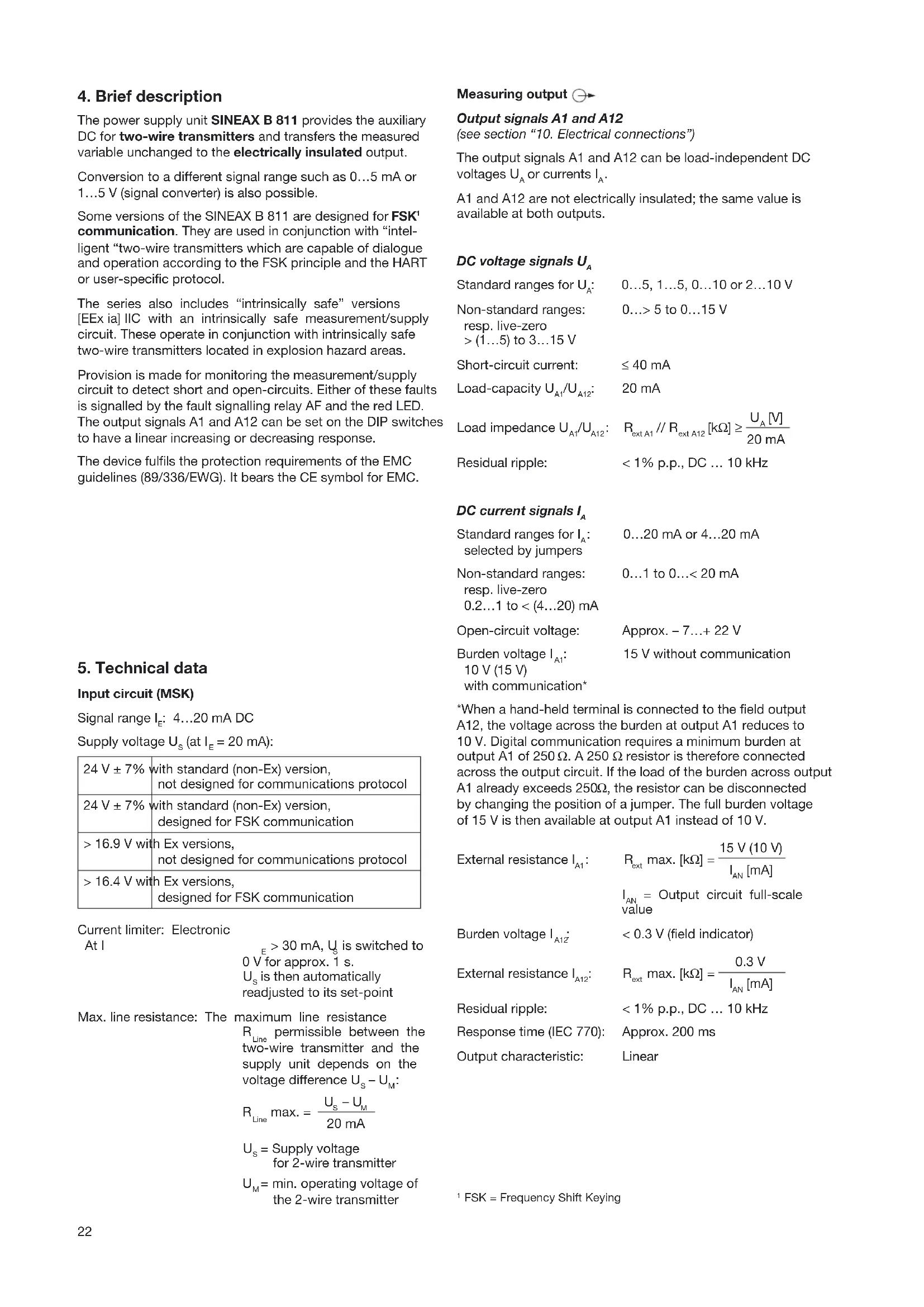
The power supply unit SINEAX B 811 provides the auxiliary DC for two-wire transmitters and transfers the measured variable unchanged to the electrically insulated output.
Conversion to a different signal range such as 0... 5mA or 1... 5V (signal converter) is also possible.
Some versions of the SINEAX B 811 are designed for FSK communication. They are used in conjunction with "intelligent two-wire transmitters which are capable of dialogue and operation according to the FSK principle and the HART or user-specific protocol.
The series also includes "intrinsically safe" versions [EEx ia] IIC with an intrinsically safe measurement/supply circuit. These operate in conjunction with intrinsically safe two-wire transmitters located in explosion hazard areas.
Provision is made for monitoring the measurement/supply circuit to detect short and open-circuits. Either of these faults is signalled by the fault signalling relay AF and the red LED. The output signals A1 and A12 can be set on the DIP switches to have a linear increasing or decreasing response.
The device fulfils the protection requirements of the EMC guidelines (89/336/EWG). It bears the CE symbol for EMC.
5. Technical data
Input circuit (MSK)
Signal range IE : 4.5 - 20 mADC
Supply voltage US (at IE = 20 mA ):
| 24 V ± 7% | with standard (non-Ex) version, not designed for communications protocol |
| 24 V ± 7% | with standard (non-Ex) version, designed for FSK communication |
| >16.9 V with Ex versions, not designed for communications protocol | |
| >16.4 V with Ex versions, designed for FSK communication | |
Current limiter: Electronic
At I
E > 30mA,Us is switched to 0V for approx.1 s. Us is then automatically readjusted to its set-point
Max. line resistance: The maximum line resistance
RLine permissible between the two-wire transmitter and the supply unit depends on the voltage difference US - UM
R _ Line . = U _ S - U _ M2 0 mA
U = Supply voltage for 2-wire transmitter
UM = operating voltage of the 2-wire transmitter
Measuring output
Output signals A1 and A12
(see section "10. Electrical connections")
The output signals A1 and A12 can be load-independent DC voltages UA or currents IA .
A1 and A12 are not electrically insulated; the same value is available at both outputs.
DC voltage signals UA
Standard ranges for UA .. 0...5, 1...5, 0...10 or 2...10 V
Non-standard ranges: 0...>5 to 0...15 V resp. live-zero > (1...5) to 3...15 V
Short-circuit current: ≤ 40mA
Load-capacity UA1 / UA12 20mA
Load impedance UA1 / UA12 .. RextA1 / / RextA12[kΩ ]≥ A[V]20mA
Residual ripple: < 1% p.p., DC ... 10 kHz
DC current signals IA
Standard ranges for IA ..20 mA or 4..20 mA selected by jumpers
Non-standard ranges: 0...1 to 0... < 20 mA resp. live-zero 0.2...1 to < 4... 20 mA
Open-circuit voltage: Approx. -7... +22V
Burden voltage IA1 15 V without communication
10 V (15 V)
with communication*
*When a hand-held terminal is connected to the field output A12, the voltage across the burden at output A1 reduces to 10 V. Digital communication requires a minimum burden at output A1 of 250 Ω. A 250 Ω resistor is therefore connected across the output circuit. If the load of the burden across output A1 already exceeds 250Ω, the resistor can be disconnected by changing the position of a jumper. The full burden voltage of 15 V is then available at output A1 instead of 10 V.
External resistance IA1 : Rext . [kΩ] = 15 V(10 V)IAN[mA]
IAN = Output circuit full-scale value
Burden voltage IA1Z < 0.3V field indicator)
External resistance IA12 : Rext . [kΩ] = 0.3 VIAN [mA]
Residual ripple: < 1% p.p., DC ... 10 kHz
Response time (IEC 770): Approx. 200 ms
Output characteristic: Linear
FSK = Frequency Shift Keying
Power supply H →
AC/DC power pack (DC and 45...400 Hz)
Table 1: Nominal voltages and tolerances
| Nominal voltage UN | Tolerance | Instrument version |
| 24 ... 60 V DC/AC | DC - 15 ... + 33% AC ± 15% | Standard (non-Ex) |
| 85 ... 230 V1 DC/AC | ||
| 24 ... 60 V DC/AC | DC - 15 ... + 33% AC ± 15% | Type of protection "Intrinsically safe" [EEx ia] IIc |
| 85 ... 230 V AC ± 10% | ||
| 85 ... 110 V DC - 15 | ... + 10% |
1 For power supplies >125V the auxiliary circuit should include an external fuse.
Power input: Approx. 2.5 W resp. ≤ 3 VA
Communication
Bi-directional communication of digital signals with an "in-telligent" two-wire transmitter designed for FSK and a HART or company-specific protocol.
Frequency range: 500Hz ... 35 kHz
Input circuit monitor

Pick-up level: - Open-circuit Input current < 3.6mA adjustable in the works between 1 and 4 mA
Short-circuit Input current >21mA adjustable in the works between 20 and 23mA
Signalling modes
Output signals
A1 and A12: - Linear output signal For an open-circuit output
0 mA (with 4...20 mA)
-
5 mA (with 0...20 mA)
For a short-circuit output approx. 26 mA -
Increasing
output signal
Output approx. 115% of full-scale value, e.g. 23mA for output 0/4...20 mA or 11.5 V for output 0/2...10 V
- Decreasing
output signal
(only possible for live zero) Output approx. 10% of fullscale value, e.g. 2 mA for output 4...20 mA or 1 V for output 2...10 V
Frontplate signals: Output contact AF
Failure signalled by red LED
1 relais, 1 potentially-free changeover contact (see Table 2)
Table 2: Type of output contact
| Symbol | Material | Contact rating |
| Gold flashed silver alloy | AC: ≤2 A/250 V (500 VA) DC: ≤1 A/0.1...250 V (30 W) |
Relay approved by UL, CSA, TUV, SEV
Direction of action: Adjustable by switch
Relay "energized" or "de-energized" in the case of a failure
Accuracy data (acc. to DIN/IEC 770)
Basic accuracy: Limit error ≤ ± 0.2%
Including linearity and reproducibility errors
Environmental conditions
Commissioning
temperature: -10 to +55 °C
Operating temperature: -25 to +55 °C, Ex-20 to +55 °C
Storage temperature: -40 to +70 °C
Annual mean
relative humidity: ≤ 75% standard climatic rating ≤ 95% enhanced climatic rating
Altitude: 2000 m max.
Vibration (IEC 68 T2/6): 2g / 5... 150... 5Hz
1 octave/min., 2 h
Shock (IEC 68 T2/27): 30g / 11ms
Indoor use statement!
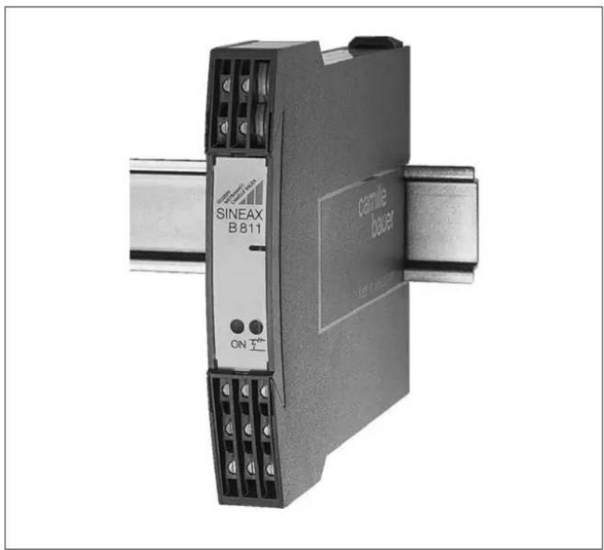
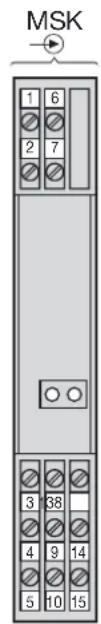
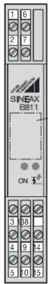
6. Overview of the parts
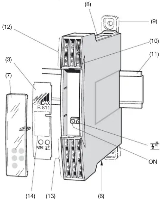
Figure 2 shows those parts of the device of consequence for mounting, electrical connections and other operations described in the Operating Instructions.
Fig. 2
(3) Front plate (12) Terminals
(6) Type label (13) Terminals
(operating data) (14) Space for notes
(7) Transparent cover ON Green LED for signalling
(8) Type label (device ratings) operating status
(9) Fixing bracket
(10) Opening for withdrawing clip (for opening the housing)
(11) Top-hat rail 35 × 15 mm or 35 × 7,5 mm (EN 50 022)
7. Exchanging frontplates
Apply gentle pressure to the transparent cover as shown in Fig. 3 until pops out on the opposite side. The label in the cover can be replaced and used for notes.
After replacing the label in the transparent cover, the transparent cover can be snapped into the front of the device again. This is done by inserting it behind the edge at the bottom and pressing it gently down and to the rear with the finger until it snaps into place (right side of Fig. 3).
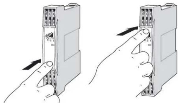
Fig.3.Left:Removing the transparent cover Right: Inserting the transparent cover.
8. Withdrawing and inserting the device
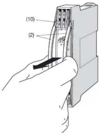
Fig. 4
Insert the withdrawing handles (2) into the openings (10) until they snap into place. Withdraw the front part together with the main PCB out of the housing.
To reassemble the unit, insert the front part together with the main PCB into the housing until the swallow-tailed sections engage in each other.
9. Mounting
The SINEAX B 811 can be mounted either on a top-hat rail or directly onto a wall or mounting plate.

Make sure that the ambient temperature stays within the permissible limits:
-25 and +55ircC for standard instruments
-20 and + 55 °C for instruments in Ex versions!
9.1 Top-hat rail mounting
Simply clip the device onto the top-hat rail (EN 50 022) (see Fig. 5).
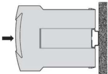
Fig. 5. Mounting on top-hat rail 35 × 15 or 35 × 7.5 mm .
9.2 Wall mounting
While pressing the latch (4) in the base of the device (Fig. 5, left) pull out the transmitter securing brackets (1). To return the brackets to their original positions, the latch (5) in the base of the device has to be depressed before applying pressure to the securing brackets (1) (see Fig. 5, right).
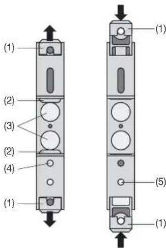
Fig. 6. Rear of device.
(1) Screw hole brackets
(2) Top-hat rail clip
(3) Rubber buffers
(4) Latch for pulling the screw hole brackets out
(5) Latch for pushing the screw hole brackets in
Drill 2 holes in the wall or panel as shown in the drilling pattern (Fig. 7). Now secure the power pack to the wall or panel using two 4mm diameter screws.
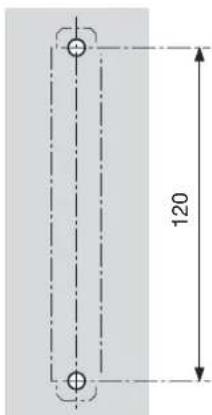
Fig. 7. Drilling pattern.
10. Electrical connections
The electrical connections are made to screw terminals which are easily accessible from the front of the power pack (see Fig. 8 to 13) and can accommodate wire gauges up to max. 2,5mm2
Make sure that the cables are not live when making the connections!
The 230 V power supply and 250 V contact output is potentially dangerous!


Observe all local regulations (e.g. VDE 0100 "Conditions for installing heavy current plant with rated voltages lower than 1000 volts" in Germany) when selecting the type of electrical cable and installing them!
In the case of "Intrinsically safe" explosionproof versions [EEx ia] IIC, the supplementary information given on the type examination certification, the EN 60 079-14, and also local regulations applicable to electrical installation in explosion hazard areas must be taken into account.

Note that, ...
... the data required to perform the electrical insulation task agree with the data on the nameplate of the SINEAX B 811 input circuit output A1, A12, AF et power supply H!
... the input and output cables should be twisted pairs and run as far as possible away from heavy current cables!
In all other respects, observe all local regulations when selecting the type of electrical cable and installing them!
Front
Without transparent cover
With transparent cover
Space e.g. for MSK designation
ON
Green LED device standing by
五
Red LED open and short-circuit monitor of input circuit
MSK
A1
HHT
A12
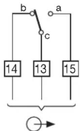
Relay
AF
H
N/O contact: a-c
N/C contact: b-c
MSK = Input circuit
(terminal allocation according to type, see Figs. 8 to 13)
A1 = Measuring output
A12 = 2nd. measuring output (field indicator) voltage drop across field indicator or milliammeter ≤ 300mV , resp. connection for hand held terminal
AF = Output contact for monitoring the input circuit (fault signalling output) Refer to the figure "relay" for details
HHT = Hand held terminal
H = Power supply
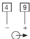
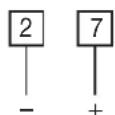
10.1 Connection of the input circuit, output and power supply leads
| Safe area X X E 4...20 mA 1 6 2-wire transmitter Connection of an HHT-1 (terminals 2 and 7 connected directly to terminals 1 and 6) HHT-1 A1 A12 AF H~(-) (+) | Hazardous area X X E 4...20 mA 2-wire transmitter Connection of an HHT-1 (terminals 2 and 7 connected directly to terminals 1 and 6) HHT-1 A1 A12 AF H~(-) (+) |
| * Note data given in the conformity certificate. Fig. 9. SINEAX type 811-1..0 ....., intrinsically safe input circuit, supply voltage U_s 24 V DC, not designed for FSK. | |
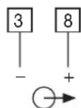
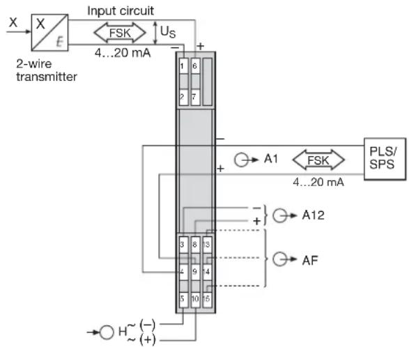
| Safe area X X E 4...20 mA 2-wire transmitter Connection of an HHT-1 (terminals 2 and 7 connected directly to terminals 1 and 6) HHT-1 A1 0/4...20 mA FSK + A12 AF HHT-1 A1 0/4...20 mA FSK + A12 AF HHT-1 A1 0/4...20 mA FSK + A12 AF HHT-1 A1 0/4...20 mA FSK + A12 AF HHT-1 A1 0/4...20 mA FSK + A12 AF | Hazardous area X X E 4...20 mA 2-wire transmitter Connection of an HHT-1 (terminals 2 and 7 connected directly to terminals 1 and 6) HHT-1 A1 0/4...20 mA FSK + A12 AF HHT-1 A1 0/4...20 mA FSK + A12 AF HHT |
| Fig. 10. SINEAX type 811-1..1 ..., non-Ex input and output circuits, supply voltage U_s 24 V DC, designed for FSK. Hand-held terminal connected to field output A12. | Fig. 11. SINEAX type 811-1..1 ..., intrinsically safe input circuit, supply voltage U_s 16.4 V DC, designed for FSK. Hand-held terminal connected to field output A12. |
Safe area
Fig.12.SINEAX type 811-1..2..., non-Ex input and output circuits, supply voltage Us 24 V DC, designed for FSK. Processor connected to output A1
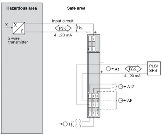
Fig.13.SINEAX type 811-1..2..., intrinsically safe input circuit, supply voltage Us 16.4 V DC, designed for FSK. Processor connected to output A1.
10.2 Connection of the hand held terminal HHT to field output A12
The FSK version of the power supply unit SINEAX B 811 can also transmit a frequency modulated digital signal in addition to the analogue signal and the power supply. Depending on the version of the power supply unit, connect the hand-held terminal HHT to the communication output terminal A12 as shown in either Fig. 10 or Fig. 11.

When a hand held terminal is connected to field output A12, the voltage across the burden at output A1 reduces to 10V . Digital communication requires a minimum burden at output A1 of 250Ω . A 250Ω resistor is therefore connected across the output circuit. If the load of the burden across output A1 already exceeds 250Ω , the resistor can be disconnected by changing the position of a jumper (see Section 11.2 "Communication connector"). The full burden voltage of 15V is then available at output A1 instead of 10V . Also observe the rules for connecting to the communication system.
Output A12 is no longer available on this version as a second measuring output. It is not permissible to connect an ammeter to output A12.
10.3 Communication connector on A1
Depending on the version of the power supply unit, connect the processor to either Fig. 12 or Fig. 13.

The burden of the communication circuit must be at least 250Ω .Also observe the rules for connecting to the communication system.
10.4 Connection of the hand-held terminal HHT to a non-FSK power supply unit SINEAX B 811
This version of the power supply unit is equipped with terminals 2 and 7 which are electrically connected to terminals 1 and 6. Depending on the version of the power supply unit, connect the hand-held terminal HHT as shown in either Fig. 8 or Fig. 9.

It is important to note the details on the conformity certificate for the HHT in the case of power supply units SINEAX type 811-1..0 ...., with intrinsically safe measurement/supply circuit (Fig. 9). Also observe the rules for connecting to the communication system.
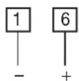
10.5 Connection of power supply leads
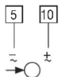
Connect the power supply to terminals 5 (=) and 10(±) . A two-pole switch must be included in the supply connection where facility for switching SINEAX B 811 off is desired.
Note: An external supply fuse must be provided for DC supply voltage >125V
11. Configuration
The SINEAX B 811 unit has to be opened before it can be configured (see Section 8. "Withdrawing and inserting the device").
11.1 Switching output signals A1 and A12 between the signal ranges 0...20 mA or 4...20 mA
The range of the outputs can be switched from 0...20 mA to 4...20 mA or vice versa depending on the positions of jumpers J 202 and J 203 (Fig. 14).
| Output signals A1 / A12 | Position of jumper J 202 J 203 | |
| 4 ... 20 mA 1 1 | ||
| 0 ... 20 mA 3 3 | ||
11.2 Communication connector
Connect the communication connector to output A1 or A12 (Figs. 10 to 13). Signals are then transferred in both directions between the hand-held terminal and the transmitter via the SINEAX B 811.
When using the field output A12, the 250 Ω burden connected across output A12 in the power supply unit can be switched in and out of circuit with the aid of jumpers J 204 and J 205 (Fig. 14).
| Communication connected to: | Position of jumpers | |
| J 204 | J 205 | |
| Field output A12* integrated 250 Ω resistor in circuit, the burden at measuring output A1 is reduced 250 Ω | 1 | 1 |
| Choice of A1 output signal range 0/4 ... 20 mA | ||
| Voltage across A1 burden: 10 V | ||
| Field output A12* integrated 250 Ω resistor not in circuit, the burden at measuring output A1 is not reduced | 1 | 3 |
| A1 output signal range 4...20 mA only | ||
| Voltage across A1 burden: 15 V | ||
| Measuring output A1 Output signal range 4 ... 20 mA | 3 | 3 |
| Voltage across A1 burden: 15 V | ||
*See "Measuring output" in the section "5. Technical data".
11.3 Response of the output signals A1 and A12 for a fault in the measurement/supply circuit
The response of the output signals A1 and A12 can be set with the aid of switches 1 and 2 on the DIP switch S 201 (Fig. 14).
| Response of output signals A1 and A12 for a short or open-circuit of the measurement/supply circuit | Dip switch S 201 | |
| Switch 1 | Switch 2 | |
| Linear output signal ON OFF | ||
| Increasing output signal | OFF | OFF |
| Decreasing output signal (only with live zero signal) | OFF ON | |
| Fault | Output linear behaviour | Output driving upscale | Output driving downscale |
| Break | 0 mA (with output 4...20 mA) - 5 mA (with output 0...20 mA) | Approx. 115% of full scale end value e.g.. 23 mA with output 0/4...20 mA or 11.5 V with output 0/2...10 V | (with live-zero only) Approx. 10% of full scale end value e.g. 2 mA with output 4...20 mA or 1 V with output 2...10 V |
| Short-circuit | Approx. 26 mA with output 0/4...20 mA |
11.4 Response of the output contact AF for a fault in the measurement/supply circuit
The response of the fault signalling relay can be set with the aid of switches 3 and 4 on the DIP switch S 201 (Fig. 14).
| Operating sense of the fault signalling relay AF in the event of a fault | Dip switch S 201 | |
| Switch 3 | Switch 4 | |
| Relay energised | ON | OFF |
| Relay de-energised | OFF | ON |
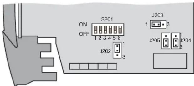
Fig. 14. Positions of the DIP switches S 201 and jumpers J 202 to J 205.
12. Commissioning
| The power supply unit must be capable of sup- lying a brief current surge when switching on. The transmitter presents a low impedance at the instant of switching which requires a current ISat of ... |
| ...ISTart approx. 250 mA for the version with a power supply range 24 - 60 V DC/AC |
| or |
| ...ISTart approx. 100 mA for the version with a power supply range 85 - 230 V DC/AC |
| The red LED may also light briefly (< 1 s). The green LED must light immediately. |
| The signal for indicating a failure in the measure - ment/Supply circuit is only enabled after a delay of typically 2.5 s. The output contact remains in its reset state during the switch-on delay! |
13. Releasing the power pack
Release the power pack from a top-hat rail as shown in Fig. 15.
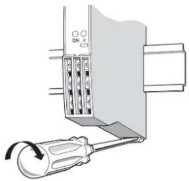
Fig. 15
14. Dimensional drawings
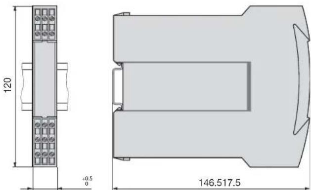
Fig. 16. SINEAX B 811 in housing S17 clipped onto a top-hat rail (35× 15mm or 35× 7.5mm , acc. to EN 50 022).
15. Declaration of conformity
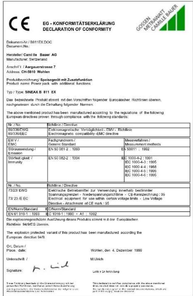
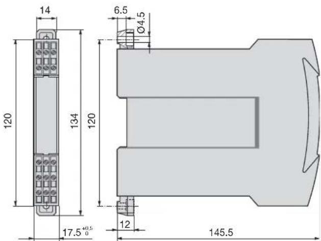
Fig. 17. SINEAX B 811 in housing S17 screw hole mounting brackets pulled out.


- Betriebsanleitung
- Operating Instructions
- Inhaltsverzeichnis
- Attestation Ex (4)
- Tension continue UA
- SINEAX B 811EX
- Read first and then ...
- are observed.
- Scope of supply (Fig. 1)
- Power pack (1)
- Specification and ordering information
- Brief description
- Technical data
- Input circuit (MSK)
- Measuring output
- Output signals A1 and A12
- DC voltage signals UA
- DC current signals IA
- Power supply H →
- Communication
- Input circuit monitor
- Signalling modes
- Environmental conditions
- Overview of the parts
- Exchanging frontplates
- Withdrawing and inserting the device
- Mounting
- Top-hat rail mounting
- Wall mounting
- Electrical connections
- Connection of the input circuit, output and power supply leads
- Connection of the hand held terminal HHT to field output A12
- Communication connector on A1
- Connection of the hand-held terminal HHT to a non-FSK power supply unit SINEAX B 811
- Connection of power supply leads
- Configuration
- Switching output signals A1 and A12 between the signal ranges 0...20 mA or 4...20 mA
- Communication connector
- Response of the output signals A1 and A12 for a fault in the measurement/supply circuit
- Response of the output contact AF for a fault in the measurement/supply circuit
- Commissioning
- Releasing the power pack
- Dimensional drawings
- Declaration of conformity
Brand : Camille Bauer
Model : Sineax B811
Category : Industrial power supply