
GMR 1 Professional - Electric router BOSCH - Free user manual and instructions
Find the device manual for free GMR 1 Professional BOSCH in PDF.
| Brand | Bosch |
| Model | GMR 1 Professional |
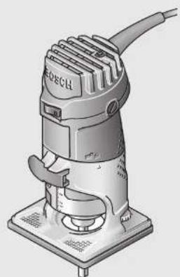
| Product type | Electric router |
| Rated power input | 550 W |
| No-load speed | 33,000 rpm |
| Tool holder (collet chuck) | 6 mm (1/4 in) |
| Weight (according to EPTA 01/2003) | 1.5 kg |
| Protection class | II (double insulation) |
| Rated voltage | 230/240 V |
| Frequency | 50/60 Hz |
| Adjustable routing depth | Yes, with knob and scale |
| Workable materials | Wood, plastics, lightweight construction materials |
| Included accessories | 17 mm open-end wrench, 6 mm collet chuck |
| Optional accessories | Copy ring, parallel guide, guide aid, carriage housing |
| Main functions | Routing grooves, edges, profiles, copying |
| Clamping system | Clamping lever and union nut with collet |
| Spindle lock | Yes, for tool change |
| Switch | On/Off with two positions |
| Maintenance and cleaning | Clean ventilation slots with a brush or compressed air |
| Repairability | Bosch after-sales service, spare parts available at bosch-pt.com |
| Safety | Wearing gloves and safety goggles recommended, disconnect before adjustments |
Frequently Asked Questions - GMR 1 Professional BOSCH
User questions about GMR 1 Professional BOSCH
0 question about this device. Answer the ones you know or ask your own.
Ask a new question about this device
Download the instructions for your Electric router in PDF format for free! Find your manual GMR 1 Professional - BOSCH and take your electronic device back in hand. On this page are published all the documents necessary for the use of your device. GMR 1 Professional by BOSCH.
USER MANUAL GMR 1 Professional BOSCH
OBJ_DOKUC-4175-003 fm Page 1 Wednesday, April 22, 2009 10:25 AM
Robert Bosch GmbH
Power Tools Division
70745 Leinfelden-Echterdingen
Germany
www.bosch-pt.com
2609140653(2009.04)PS/84ASIA
GMR 1 Professional

BOSCH
en Original instructions
cn 正本使用说明书
tw正本使用說明書
ko
th
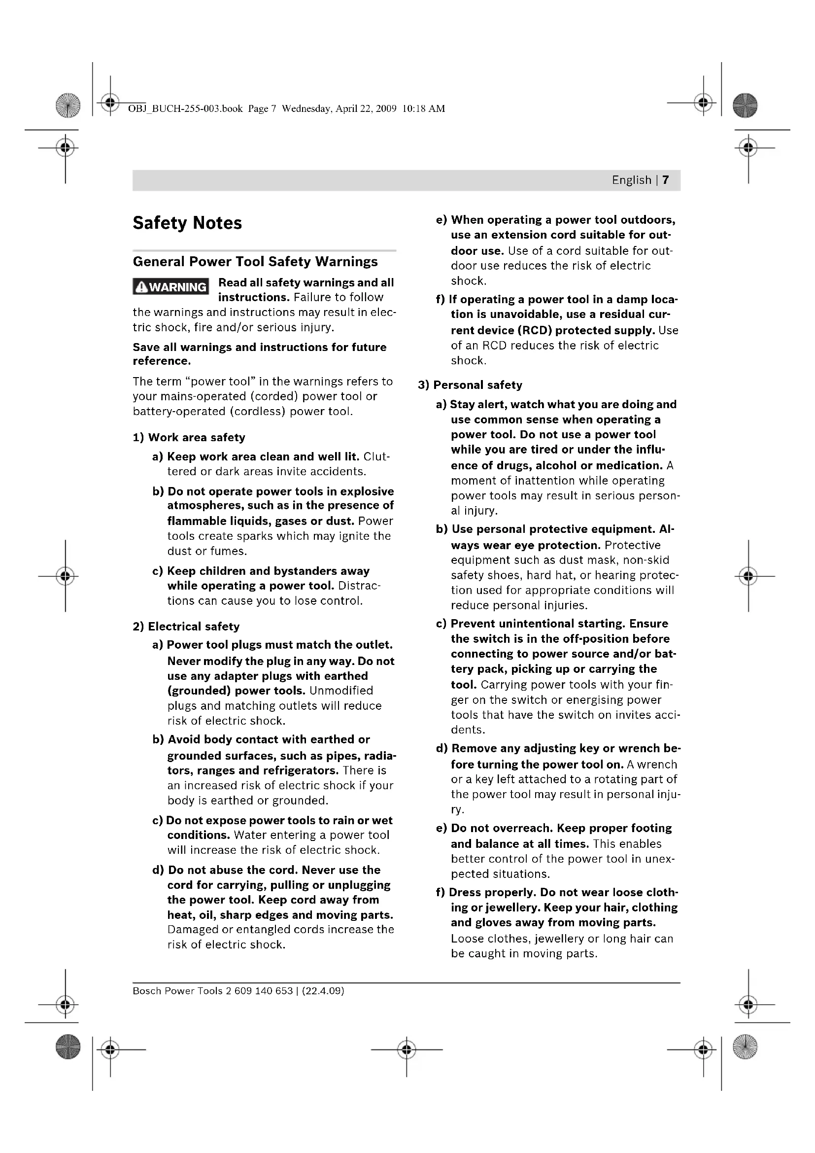
General Power Tool SafetyWarnings
WARNING
Read all safety warnings and all instructions. Failure to follow
the warnings and instructions may result in electric shock, fire and/or serious injury.
Save all warnings and instructions for future reference.
The term "power tool" in the warnings refers to your mains-operated (corded) power tool or battery-operated (cordless) power tool.
1) Work area safety
a) Keep work area clean and well lit. Cluttered or dark areas invite accidents.
b) Do not operate power tools in explosive atmospheres, such as in the presence of flammable liquids, gases or dust. Power tools create sparks which may ignite the dust or fumes.
c) Keep children and bystanders away while operating a power tool. Distractions can cause you to lose control.
2) Electrical safety
a) Power tool plugs must match the outlet. Never modify the plug in any way. Do not use any adapter plugs with earthed (grounded) power tools. Unmodified plugs and matching outlets will reduce risk of electric shock.
b) Avoid body contact with earthed or grounded surfaces, such as pipes, radiators, ranges and refrigerators. There is an increased risk of electric shock if your body is earthed or grounded.
c) Do not expose power tools to rain or wet conditions. Water entering a power tool will increase the risk of electric shock.
d) Do not abuse the cord. Never use the cord for carrying, pulling or unplugging the power tool. Keep cord away from heat, oil, sharp edges and moving parts. Damaged or entangled cords increase the risk of electric shock.
e) When operating a power tool outdoors, use an extension cord suitable for outdoor use. Use of a cord suitable for outdoor use reduces the risk of electric shock.
f) If operating a power tool in a damp location is unavoidable, use a residual current device (RCD) protected supply. Use of an RCD reduces the risk of electric shock.
3) Personal safety
a) Stay alert, watch what you are doing and use common sense when operating a power tool. Do not use a power tool while you are tired or under the influence of drugs, alcohol or medication. A moment of inattention while operating power tools may result in serious personal injury.
b) Use personal protective equipment. Always wear eye protection. Protective equipment such as dust mask, non-skid safety shoes, hard hat, or hearing protection used for appropriate conditions will reduce personal injuries.
c) Prevent unintentional starting. Ensure the switch is in the off-position before connecting to power source and/or battery pack, picking up or carrying the tool. Carrying power tools with your finger on the switch or energising power tools that have the switch on invites accidents.
d) Remove any adjusting key or wrench before turning the power tool on. A wrench or a key left attached to a rotating part of the power tool may result in personal injury.
e) Do not overreach. Keep proper footing and balance at all times. This enables better control of the power tool in unexpected situations.
f) Dress properly. Do not wear loose clothing or jewellery. Keep your hair, clothing and gloves away from moving parts. Loose clothes, jewellery or long hair can be caught in moving parts.

8 | English
g) If devices are provided for the connection of dust extraction and collection facilities, ensure these are connected and properly used. Use of dust collection can reduce dust-related hazards.
4) Power tool use and care
a) Do not force the power tool. Use the correct power tool for your application. The correct power tool will do the job better and safer at the rate for which it was designed.
b) Do not use the power tool if the switch does not turn it on and off. Any power tool that cannot be controlled with the switch is dangerous and must be repaired.
c) Disconnect the plug from the power source and/or the battery pack from the power tool before making any adjustments, changing accessories, or storing power tools. Such preventive safety measures reduce the risk of starting the power tool accidentally.
d) Store idle power tools out of the reach of children and do not allow persons unfamiliar with the power tool or these instructions to operate the power tool. Power tools are dangerous in the hands of untrained users.
e) Maintain power tools. Check for misalignment or binding of moving parts, breakage of parts and any other condition that may affect the power tool's operation. If damaged, have the power tool repaired before use. Many accidents are caused by poorly maintained power tools.
f) Keep cutting tools sharp and clean. Properly maintained cutting tools with sharp cutting edges are less likely to bind and are easier to control.
g) Use the power tool, accessories and tool bits etc. in accordance with these instructions, taking into account the working conditions and the work to be performed. Use of the power tool for operations different from those intended could result in a hazardous situation.
5) Service
a) Have your power tool serviced by a qualified repair person using only identical replacement parts. This will ensure that the safety of the power tool is maintained.
SafetyWarnings for Routers
The allowable speed of the router bit must be at least as high as the maximum speed listed on the power tool. Accessories that rotate faster than permitted can be destroyed.
Router bits or other accessories must fit exactly in the tool holder (collet) of your machine. Routing bits that do not fit precisely in the tool holder of the machine rotate irregularly, vibrate heavily and can lead to loss of control.
Apply the machine to the workpiece only when switched on. Otherwise there is danger of kickback when the cutting tool jams in the workpiece.
- Never cut over metal objects, nails or screws. The router bit can become damaged and lead to increased vibrations.
Hold the power tool only by the insulated gripping surfaces when performing an operation where the cutting tool may contact hidden wiring or its own cord. Contact with a "live" wire will also make exposed metal parts of the power tool "live" and shock the operator.
Use appropriate detectors to determine if utility lines are hidden in the work area or call the local utility company for assistance. Contact with electric lines can lead to fire and electric shock. Damaging a gas line can lead to explosion. Penetrating a water line causes property damage or may cause an electric shock.
Do not use blunt or damaged router bits. Blunt or damaged router bits cause increased friction, can become jammed and lead to imbalance.
- Secure the workpiece. A workpiece clamped with clamping devices or in a vice is held more secure than by hand.
English | 9
Always wait until the machine has come to a complete stop before placing it down. The tool insert can jam and lead to loss of control over the power tool.
- Never use the machine with a damaged cable. Do not touch the damaged cable and pull the mains plug when the cable is damaged while working. Damaged cables increase the risk of an electric shock.
Products sold in GB only: Your product is fitted with an BS 1363/A approved electric plug with internal fuse (ASTA approved to BS 1362). If the plug is not suitable for your socket outlets, it should be cut off and an appropriate plug fitted in its place by an authorised customer service agent. The replacement plug should have the same fuse rating as the original plug. The severed plug must be disposed of to avoid a possible shock hazard and should never be inserted into a mains socket elsewhere.
Products sold in AUS and NZ only: Use a residual current device (RCD) with a rated residual current of 30mA or less.
Functional Description

Read all safety warnings and all instructions. Failure to follow the warnings and instructions may result in electric shock, fire and/or serious injury.
While reading the operating instructions, unfold the graphics page for the machine and leave it open.
Intended Use
The machine is intended for routing grooves, edges, profiles and elongated holes as well as for copy routing in wood, plastic and light building materials, while resting firmly on the workpiece.
Product Features
The numbering of the components shown refers to the representation of the power tool on the graphic pages.
1 Motor unit
2 Routing base
3 Thumbwheel for depth-of-cut fine adjustment
4 Router bit*
5 Tightening nut with collet
6 Guide plate
7 Base plate
8 Scale for depth-of-cut
9 Spindle lock button
10 Clamping lever
11 On/Off switch
12 Collet chuck
13 Tool holder
14 Open-end spanner (17 mm)
15 Base cover sleeve
16 Guide bushing*
17 Parallel guide
18 Wing bolt for attachment of side stop
19 Wing bolt for parallel guide
20 Roller guide *
21 Roller
22 Wing bolt for locking of the horizontal alignment
23 Wing bolt for horizontal alignment of the roller guide
24 Nut for adjustment of the tensioning force
*Accessories shown or described are not part of the standard delivery scope of the product. A complete overview of accessories can be found in our accessories program.
10 | English
Technical Data
| Plunge router GMR 1 | Professional | |
| Article number | 3 601 FOA 0.. | |
| Rated power input | W | 550 |
| No-load speed | min-1 | 33000 |
| Tool holder | mm | 6 |
| inch | 1/4 | |
| Weight according to EPTA-Procedure 01/2003 | kg 1.5 | |
Protection class
回/II
The values given are valid for nominal voltages [U] of 230/240 V. For lower voltage and models for specific countries, these values can vary.
Please observe the article number on the type plate of your machine. The trade names of the individual machines may vary.
Assembly
Changing the Tool
Before any work on the machine itself, pull the mains plug.
It is recommended to wear protective gloves when inserting or replacing router bits.
Disassembling the Routing Base (see figure A)
Before a router bit can be inserted, the routing base 2 must first be removed from the motor unit 1.
- Open the clamping lever 10 and turn the routing base 2 so that the mark is in line with the symbol on the motor unit 1.
- Pull the motor unit upward to the stop.
- Turn the motor unit in anticlockwise direction to the stop and pull it out of the routing base.
Replacing the Collet (see figure B)
Depending on the routing tool being used, the tightening nut with the collet 5 may need to be replaced before inserting the router bit. When the right collet for your router bit is already mounted, follow the work steps as described under "Inserting a Router Bit".
The collet 12 must have somewhat play when seated in the tightening nut. The tightening nut 5 must assemble easily. Should the tightening nut or collet be damaged, replace immediately.
- Push the spindle lock button 9 and keep it pressed. If required, rotate the motor spindle by hand until it locks. (see Fig. C1)
- Unscrew the tightening nut 5 with open-end spanner 14 turning in anticlockwise direction.
- Release the spindle lock button.
- If required, clean all parts to be mounted prior to assembling, using a soft brush or by blowing out with compressed air.
- Start the new tightening nut on tool holder 13.
- Hand-tighten the tightening nut.
Do not tighten the tightening nut of the collet without a router bit inserted. Otherwise the collet can be damaged.
Inserting a Router Bit (see figures C1-C2)
Depending on the application, router bits are available in the most different designs and qualities.
Router bits made of high speed steel (HSS) are suitable for the machining of soft materials, e.g. softwood and plastic.
Carbide tipped router bits (HM) are particularly suitable for hard and abrasive materials, e. g. hardwood and aluminium.
Original router bits from the extensive Bosch accessories program are available at your specialist shop.
Only use clean router bits that are in perfect condition.


- Push the spindle lock button 9 and keep it pressed. If required, rotate the motor spindle by hand until it locks. (see Fig. C1)
- Loosen the tightening nut 5 with the open-end spanner by turning in anticlockwise direction 14. (see Fig. C2)
- Insert the router bit into the collet. The shank of the router bit must be immersed at least 20mm into the collet.
- Retighten the tightening nut by turning in clockwise direction.
- Release the spindle lock button.
Do not tighten the tightening nut of the collet without a router bit inserted. Otherwise the collet can be damaged.
Mounting the Routing Base (see figure D)
For routing, the routing base 2 must be mounted on the motor unit 1 again.
- Open the clamping lever 10 on the motor unit if locked.
- Bring the two double arrows on the motor unit and the routing base 2 into alignment.
- Push the motor unit into the routing base and turn the motor unit in clockwise direction until the mark points against the symbol.
- Push the motor unit further into the routing base.
- After mounting is completed, turn the mark on the routing base to the symbol on the motor unit.
- Lock the clamping lever.
After mounting, always check if the motor unit is seated tightly in the routing base.
If required, change the pre-tension of the clamping lever 10 (see "Readjusting the Clamping Lever", page 14).
Mounting the Base Cover Sleeve (see figure E)
Intensive use of the trimmer will cause the routing base to become hot. In this case, a base cover sleeve (accessory) can be mounted for protection of the hands.
- Remove the clamping lever 10.
- Place the base cover sleeve 15 on the routing base 2 from above.
- Reassemble the clamping lever again in such a manner that the motor unit 1 is held securely in the routing base when the clamping lever is locked.
Dust/Chip Extraction
Dusts from materials such as lead-containing coatings, some wood types, minerals and metal can be harmful to one's health. Touching or breathing-in the dusts can cause allergic reactions and/or lead to respiratory infections of the user or bystanders.
Certain dusts, such as oak or beech dust, are considered as carcinogenic, especially in connection with wood-treatment additives (chromate, wood preservative). Materials containing asbestos may only be worked by specialists.
- Provide for good ventilation of the working place.
- It is recommended to wear a P2 filter-class respirator.
Observe the relevant regulations in your country for the materials to be worked.
12 | English
Operation
Adjusting the Depth-of-cut (see figure F)
The adjustment of the depth-of-cut may only be carried out when the router is switched off.
For coarse adjustment of the depth-of-cut, proceed as follows:
- Place the machine with the router bit mounted on the workpiece to be machined.
- Open the clamping lever 10 on the motor unit if locked.
- Turn the routing base 2 so that the mark points against the symbol and slowly lower the motor unit until the router bit touches the workpiece.
- Lock the clamping lever.
- Read the measuring value off the scale 8 and note it down (zeroing). Add the desired depth-of-cut to this value.
- Open the clamping lever and adjust the motor unit to the calculated scale value.
- Turn the routing base so that the mark points against the symbol and lock the clamping lever again.
- Check the carried out depth-of-cut adjustment with a trial cut and correct it, if necessary.
For fine adjustment of the depth-of-cut, proceed as follows:
- With the clamping lever 10 open, turn the routing base so that the mark points against the symbol.
- Adjust the desired depth-of-cut with thumb-wheel 3.
- Lock the clamping lever.
Starting Operation
Observe correct mains voltage! The voltage of the power source must agree with the voltage specified on the nameplate of the machine. Power tools marked with 230 V can also be operated with 220 V.
Switching On and Off
To start the machine, set the On/Off switch 11 to I.
To switch off the machine, set the On/Off switch 11 to 0.
Working Advice
Protect router bits against shock and impact.
Direction of Feed and Routing Process (see figure G)
The feed motion of the router bit 4 must always be carried out against the rotation direction of the router bit (up-grinding). When routing in the rotation direction of the router bit (down-cutting), the machine can break loose, eliminating control by the user.
Use the machine only with the routing base 2 mounted. Loss of control over the machine can cause injuries.
Before beginning the routing procedure, check if the mark on the routing base is positioned in line with the symbol on the motor unit 1.
Note: Take into consideration that the router bit 4 always extends out of the base plate 7. Do not damage the template or the workpiece.
- Set the desired depth-of-cut (see "Adjusting the Depth-of-cut", page 12).
- Switch the machine on and guide it to the location subject to working.
- Carry out the routing process applying uniform feed.
- Switch the machine off after finishing the routing process.
Do not place the power tool down until after the router bit has come to a complete stop. Coasting application tools can cause injuries.
Routing with Guide Bushing (see figures H1-H3)
The guide bushing 16 enables template and pattern routing on workpieces.
Choose a suitable guide bushing, depending on the thickness of the template or the pattern. Because of the projecting height of the guide bushing, the template must have a minimum thickness of 8mm (see figure H1)
-
Select a router bit with a diameter smaller than the interior diameter of the guide bushing.
-
Unscrew the four pan head screws on the bottom side of the guide plate 6 and remove the guide plate.
Insert the guide bushing 16 into the guide plate. (see figure H2) - Screw the guide plate loosely onto the base plate 7 again. The guide plate must be able to move freely.
To ensure that the distance from router bit centre and guide bushing edge is uniform, the guide bushing and the guide plate must be adjusted to each other, if required.
Align the guide plate in such a manner that router bit and guide bushing are centred to the guide plate opening. (see figure H3)
Hold the guide plate in this position and tighten the fastening screws.
For routing with the guide bushing 16 proceed as follows:
- Place the machine with the guide bushing 16 against the template.
- Guide the switched on power tool with the protruding guide bushing alongside the template applying lateral pressure.
Shaping or Molding Applications (see figure 1)
For shaping or molding applications without the use of a parallel guide, the router bit must be equipped with a pilot or a ball bearing.
- Guide the switched on power tool from the side toward the workpiece until the pilot or the ball bearing of the router bit faces against the workpiece edge to be machined.
- Guide the machine alongside the workpiece edge. Ensure rectangular support. Excessive pressure can damage the edge of the workpiece.
Routing with Parallel Guide (see figure K)
For edge-parallel cuts, mount the parallel guide 17.
- Fasten the parallel guide 17 to the routing base 2 with wing bolt 18.
- Adjust the desired depth setting with wing bolt 19 on the parallel guide.
- Guide the switched on power tool with uniform feed and lateral pressure on the parallel guide alongside the workpiece edge.
Routing with Roller Guide (see figure L)
The roller guide 20 is used for routing edges with router bits without pilot or ball bearing.
- Fasten the roller guide 2 to the routing base with wing bolt 18.
- Guide the machine with uniform feed alongside the workpiece edge.
Lateral Clearance: In order to change the amount of material removal, the lateral clearance between workpiece and the guide roller 21 of the roller guide 20 can be adjusted.
- Loosen wing bolt 22, adjust the desired lateral clearance by turning wing bolt 23 and tighten wing bolt 22 again.
Height: Adjust the vertical alignment of the roller guide depending on the router bit in use and the thickness of the material to be worked.
- Loosen wing bolt 18 on the roller guide, move the roller guide to the desired position and tighten the wing bolt again.


14 | English
Readjusting the Clamping Lever (see figure M)
When the motor unit 1 is no longer tightly seated in the routing base, the tensioning force of the clamping lever 10 must be readjusted.
-
Open the clamping lever.
-
T u r n n u t 24 approx. 45^ in cloci tion with an open-end spanner (size 8 mm).
- Tighten the clamping lever again.
- Check if the motor unit is clamped securely. Do not over-tighten the nut.
Maintenance and Service
Maintenance and Cleaning
Before any work on the machine itself, pull the mains plug.
For safe and proper working, always keep the machine and ventilation slots clean.
If the replacement of the supply cord is necessary, this has to be done by Bosch or an authorized Bosch service agent in order to avoid a safety hazard.
If the machine should fail despite the care taken in manufacturing and testing procedures, repair should be carried out by an after-sales service centre for Bosch power tools.
In all correspondence and spare parts order, please always include the 10-digit article number given on the type plate of the machine.
After-sales Service and Customer Assistance
Our after-sales service responds to your questions concerning maintenance and repair of your product as well as spare parts. Exploded views and information on spare parts can also be found under:
www.bosch-pt.com
Our customer consultants answer your questions concerning best buy, application and adjustment of products and accessories.
People's Republic of China
Website: www.bosch-pt.com.cn
China Mainland
Bosch Power Tools (China) Co., Ltd.
567, Bin Kang Road
Bin Jiang District 310052
Hangzhou, P.R.China
Service Hotline: 800 8 20 84 84
Tel.: +86 (571) 87 77 43 38
Fax: +86 (571) 87 77 45 02
HK and Macau Special Administrative Regions
Robert Bosch Hong Kong Co. Ltd.
21st Floor, 625 King's Road
North Point, Hong Kong
Customer Service Hotline: +852 (21) 02 02 35
Fax: +852 (25) 90 97 62
E-Mail: info@hk.bosch.com
www.bosch-pt.com.cn
Indonesia
PT. Multi Tehaka
Kawasan Industri Pulogadung
Jalan Rawa Gelam III No. 2
Jakarta 13930
Indonesia
Tel.: +62 (21) 460 12 28
Fax: +62 (21) 46 82 68 23
E-Mail: sales@multitehaka.co.id
www.multitehaka.co.id
Phillippines
Robert Bosch, Inc.
Zuellig Building
Sen. Gil Puyat Avenue
Makati City 1200, Metro Manila
Philippines
Tel.: +63 (2) 8173231
www.bosch.com.ph
Malaysia
Robert Bosch (SEA.) Pte. Ltd.
No. 8a, Jalan 13/6
46200 Petaling Jaya,
Selangor,
Malaysia
Tel.: +6 (03) 7966 3000
Fax: +6 (03) 7958 3838
E-Mail: hengsiang.yu@my.bosch.com
Toll Free Tel.: 1 800 880 188
Fax: +6 (03) 7958 3838
www.bosch.com.sg
Thailand
Robert Bosch Ltd.
Liberty Square Building
No.287,11 Floor
Silom Road, Bangrak
Bangkok 10500
Tel.: +66 (2) 631 18 79 - 18 88 (10 lines)
Fax: +66 (2) 2384783
Robert Bosch Ltd., P. O. Box 2054
Bangkok 10501, Thailand
Bosch Service - Training Centre
2869-2869/1 Soi Ban Kluay
Rama IV Road (near old Paknam Railway)
Prakanong District
10110 Bangkok
Thailand
Tel.: +66 (2) 6717800-4
Fax: +66 (2) 249 42 96
Fax: +66 (2) 2495299
Singapore
Robert Bosch (SEA.) Pte. Ltd.
38 C Jalan Pemimpin
Singapore 915701
Republic of Singapore
Tel.: +65 (3) 50 54 94
Fax: +65 (3) 50 53 27
www.bosch.com.sg
Vietnam
Robert Bosch (SEA) Pte. Ltd - Vietnam
Representative Office
Saigon Trade Center, Suite 1206
37 Ton Duc Thang Street,
Ben Nghe Ward, District 1
HCMC
Vietnam
Tel.: +84 (8) 9111 374 - 9111 375
Fax: +84 (8) 9111376
Australia, New Zealand and Pacific Islands
Robert Bosch Australia Pty. Ltd.
Power Tools
Locked Bag 66
Clayton South VIC 3169
Customer Contact Center
Inside Australia:
Phone: +61 (01300) 307 044
Fax: +61 (01300) 307 045
Inside New Zealand:
Phone: +64 (0800) 543 353
Fax: +64 (0800) 428 570
Outside AU and NZ:
Phone: +61 (03) 9541 5555
www.bosch.com.au
Disposal
The machine, accessories and packaging should be sorted for environmental-friendly recycling.
Subject to change without notice.
16|中文
安全规章
电动工具通用安全警告
警告
a)国中国中中中中中中中中中中中中中中中中中中中中中中中中中中中中中中中中中中中中中中中中中中中中中中中中中中中中中中中中中中中中中中中中中中中中中中中中中中中中中中中中中中中中中中中中中中中中中中中中中中中中
三扎贝
金田贝三的PMP是元通子,有在的中
贝贝贝贝贝贝贝贝贝贝贝贝贝贝贝贝贝贝贝贝贝贝贝贝贝贝贝贝贝贝贝贝贝贝贝贝贝贝贝贝贝贝贝贝贝贝贝贝贝贝贝贝贝贝贝贝贝贝贝贝贝贝贝贝贝贝贝贝贝贝贝贝贝贝贝贝贝贝贝贝贝贝贝
→
告名量,吴和不平章到部动音歌自击目示。
作藥藥贝三者已贝贝之言不言,贝贝之言贝贝之言贝贝之言贝贝之言贝贝之言贝贝之言贝贝之言贝贝之言贝贝之言贝贝之言贝贝之言贝贝之言贝贝之言贝贝之言贝贝之言贝贝之言贝贝之言贝贝之言贝贝之言贝贝之言贝贝之言贝贝之言贝贝之言贝贝之言贝贝之言贝贝之
贝i时在本用到贝贝贝贝贝贝贝贝贝贝贝贝贝贝贝贝贝贝贝贝贝贝贝贝贝贝贝贝贝贝贝贝贝贝贝贝贝贝贝贝贝贝贝贝贝贝贝贝贝贝贝贝贝贝贝贝贝贝贝贝贝贝贝贝贝贝贝贝贝贝贝
甘青卫云早贝悲不忘自贝三贝歌
作藥量管自卫造非,自造当卡贝卡巴山云
→
田贝贝贝贝贝贝贝贝贝贝贝贝贝贝贝贝贝贝贝贝贝贝贝贝贝贝贝贝贝贝贝贝贝贝贝贝贝贝贝贝贝贝贝贝贝贝贝贝贝贝贝贝贝贝贝贝贝贝贝贝贝贝贝贝贝贝贝贝贝贝贝贝贝贝贝贝贝贝贝贝贝贝贝
30|
三

Robert Bosch Korea Mechanics and Electronics Ltd.
中国中
298
副:+82312764143/4148/4620
:+82312704144
古词刘郎基号
:+82312794680/4681/4682
:+82312704686
E-Mail:Bosch-pt.hotline@kr.bosch.com
Internet: www.bosch.co.kr
料引
知之的默,贝无当是国,如
别本是本的

m
35
nssuunnnnnnnnnnn
77nwnnnnnaaannnnn nnnnnnnnnnnnnnnnnnnnnnnnnnnnnnnnnnnnnnnnnnnnnnnnnnnnnnnnnnnnnnnnnnnnnnnnnnnnnnnnnnnnnnnnnnnnnnnnnnnnnnnnnnnnnnnnnnn
A
nnaaannnnnnaeaa
Aanannnnnngnnnnaaennnnnnaaaannnnnnaaannnnnnaaannnnnnaaannnnnnaaannnnnnaaannnnnnaaannnnnnaaannnnnnaaannnnnnaaannnnnnaaannnnnnaaannnnnnaaannnnnnaaannnnnnaaannnnnnaaannnnnnaaannnnnnaaannnnnnaaannnnnnaaannnnnnaaannnnnna
nunnnnnaaannnnnnaan annn nnuu
n"ww"wn"unnnnnnnnnnnnnnnnnnnnnnnnnnnnnnnnnnnnnnnnnnnnnnnnnnnnnnnnnnnnnnnnnnnnnnnnnnnnnnnnnnnnnnnnnnnnnnnnnnnnnnnnnnnnnnnnnnnnnnnnnnnnnnnnnnnnnnnnnnnnnnnnnnnnn
1)
n) nnnnnnnnnnnnnnnnnnnnnnnnnnnnnnnnnnnnnnnnnnnnnnnnnnnnnnnnnnnnnnnnnnnnnnnnnnnnnnnnnnnnnnnnnnnnnnnnnnnnnnnnnnnnnnnnnnn
u) aenlalw wwnnwwnnnnae nnnnne nnne nnnnne nnnnne nnnnne nnnnne nnnnne nnnnne nnnnne nnnnne nnnnne nnnnne nnnnne nnnnne nnnnne nnnnne nnnnne nnnnne nnnnne nnnnne nnnnne nnnnne nnnnne nnnnne nnnnne nnnnne nnnnne nnnnee
n) ananannnnnnnnnnnnnnnnnnnnnnnnnnnnnnnnnnnnnnnnnnnnnnnnnnnnnnnnnnnnnnnnnnnnnnnnnnnnnnnnnnnnnnnnnnnnnnnnnnnnnnnnnnnnnnnnnnnnnnnnnnnnnnnnnnnnnn
2) annuanennn ennnwn
n) 1nnnnae nnne nnnnne ne nnnnne nnnnne nnnnne nnnnne nnnnne nnnnne nnnnne nnnnne nnnnne nnnnne nnnnne nnnnne nnnnne nnnnne nnnnne nnnnne nnnnne nnnnne nnnnne nnnnne nnnnne nnnnne nnnnne nnnnne nnnnne nnnnnee nnnnne nnnnne nnnnne nnnnne nnnnne nnnnne nnnnne nnnnne nnnnne nnnnne nnnnne nnnnne nnnnne nnnnne nnnnne nnnnne nnnnne nnnnne nnnnne nnnnne nnnnne nnnnne nnnnne nnnnne nnnnae
u) nannnnaaennnnnnnnnnnnnnnnnnnnnnnnnnnnnnnnnnnnnnnnnnnnnnnnnnnnnnnnnnnnnnnnnnnnnnnnnnnnnnnnnnnnnnnnnnnnnnnnnnnnnnnnnnnnnnnnnnnnnnnnnnnnnnnnnn
a) aonnnae nalwnnnndnuanlunwauu nn nannnnae aeae
Wnwnnnn nn nnnnnnnnnnnnnnnnnnnnnnnnnnnnnnnnnnnnnnnnnnnnnnnnnnnnnnnnnnnnnnnnnnnnnnnnnnnnnnnnnnnnnnnnnnnnnnnnnnnnnnnnnnnnnnnnnnnnnnnnnnnnnnnnnnnnnnnnnnnnnnnnnnnn nn
wwnnnnnaaunnnae 111111111111111111111111111111
a)wnlwnnnnnaeannne nnnnne wannnnnnuuunnnnulululnnnnnnnnae annnnnnae nnnnnnnnae nnnnnnnnae nnnnnnnnae
3)
n) nnuuunnuuunnuuunnuuunnuuunnuuunnuuunnuuunnuuunnuuunnuuunnuuunnuuunnuuunnuuunnuuunnuuunnuuunnuuunnuuunnuuunnuuunnuuunnuuunnuuunnuuunnuuunnuuunnuuunnuuunnuuunnuuunnuuunnuuun\n
u) uunnnnnaaannnnnnaaennnnnnaaennnnnnaaennnnnnaaennnnnnaaennnnnnaaennnnnnaaennnnnnaaennnnnnaaennnnnnaaennnnnnaaennnnnnaaennnnnnaaennnnnnaaennnnnnaaennnnnnaaennnnnnaaennnnnnaaennnnnnaaennnnnnaaennnnnnaaannnnnnaaannnnnnaaannnnnnaaannnnnnaaannnnnnaaannnnnnaaannnnnnaaannnnnnaaannnnnnaaannnnnnaaannnnnnaaannnnnnaaannnnnnaaannnnnnaaannnnnnaaannnnnnaaannnnnnaaannnnnnaaannnnnnaaannnnnnaaennnnnnaaannnnnnaaannnnnnaaannnnnnaaannnnnnaaannnnnnaaannnnnnaaannnnnnaaannnnnnaaannnnnnaaannnnnnaaannnnnnaaannnnnnaaannnnnnaaannnnnnaaannnnnnaaannnnnnaaannnnnnaaannnnnnaa ann
a) Jauunnnae aalnuuau nnnnnae annnnae nnne ane annnnae annnnae annnnae annnnae annnnae annnnae annnnae annnnae annnnae annnnae annnnae annnnae annnnae annnnae annnnae annnnae annnnae annnnae annnnae annnnae annnnae annnnae annnnae annnnae annnnae annnnee
1) 1

mnnn
nnaaannnnnnaanennnnaananaan anananaananaananaananaananaananaananaananaananaananaananaananaananaananaananaananaananaananaananaananaananaananaananaananaananaananaananaananaananaananaananaananaananaananaananaananaananaananaananaananaananaananaananaananaananaananaananaananaananaananaan ana
Weweewewewewwewewewewewewewewewewewewewewewewewewewewewewewewewewewewewewewewewewewewewewewewewewewewewew
- 10 gen
- 15nnnne nnnnne 2
- 1
mua
Jnannnnnnaa nnaeauanennnnae nnnuuunnnnnae nnne aen annnnnnnnae anannnnnnae nnne aen annnnnnnnae nnne aen annnnnnnnae nnne aen annnnnnnnae nnne aen annnnnnnnae nnne aen annnnnnnnae nnne aen annnnnnnnae nnne aen annnnnnnnae nnne aen annnnnnnnae nnne aen annnnnnnnae nnne aen annnnnnnnae nnne aen annannnnnnae nnne aen annnnnnnnae nnne aen annnnnnnnae nnne aen annnnnnnnae nnne aen annnnnnnnae nnne aen annnnnnnnae nnne aen annnnnnnnae nnne aen annnnnnnnae nnne aen annnnnnnnae nnne aen annnnnnnnae nnne aen
Jnnnnn nn nnnn nn nnnnnnnnnnnnne
- 2nnaaannnnaa nnaaananaan anananaananaananaananaananaananaananaananaananaananaananaananaananaananaananaananaananaananaananaananaananaananaananaananaananaananaananaananaananaananaananaananaananaananaananaananaananaananaananaananaananaananaananaananaananaananaananaananaananaananaanara
-
- 1
- 1
40 | mertn
aunrnnnneannnnnnnnnnnnnnnnnnnnnnnnnnnnnnnnnnnnnnnnnnnnnnnnnnnnnnnnnnnnnnnnnnnnnnnnnnnnnnnnnnnnnnnnnnnnnnnnnnnnnnnnnnnn
10 1
- 3
一
1
LusunuusulwUusulwnnuaanew LwH 0aannnsunuusulwWssyluuun
nnaia-nnaia
11
Jauaonnnaeunnnnne 111
yuaunuunnun
Jouulnueeannnnnnnnnnnn
annnnnnaaennnnn (anwwssnau G)
1
1nnaaannnnnnae 2 nanaanennnna
nannnnnnaaennnnn nnnnnnnnne
nnaa: wannnnnne nane 4 nee ananen nn
- 39
- 1nnnnaaunnnnnae nnne nnnnnn
-
mnnnne nnnnnnnnnnnnnnnnnnnnnnnnnnnnnnnnnnnnnnnnnnnnnnnnnnnnnnnnnnnnnnnnnnnnnnnnnnnnnnnnnnnnnnnnnnnnnnnnn
aannnnnnae wannnnnnae aen nne anennnnae
mnnnnaaannnnaaennn (nnwistneu HH3)
16 nnnnnaeennnne
aannananaanannnnnnaanennnnnnaanannnnnnaanannnnnnaanannnnnnaanannnnnnaanannnnnnaanannnnnnaanannnnnnaanannnnnnaanannnnnnaanannnnnnaanannnnnnaanannnnnnaanannnnnnaanannnnnnaanannnnnnaanannnnnnaanannnnnnaanannnnnnaanannnnnnaanannnnnnaanennnnnnaanannnnnnaanannnnnnaanannnnnnaanannnnnnaanannnnnnaanannnnnnaanannnnnnaanannnnnnaanannnnnnaanannnnnnaanannnnnnaanannnnnnaanannnnnnaanannnnnnaanannnnnnaanannnnnnaanannnnnnaanannnnn
aannnnaananaananaananaananaananaananaananaananaananaananaananaananaananaananaananaananaananaananaananaananaananaananaananaananaananaananaananaananaananaananaananaananaananaananaananaananaananaananaananaananaananaananaananaananaananaananaananaananaananaananaanara anannnnnnaannnnnnnnnnnnnnnnnnnnnnnnnnnnnnnnnnnnnnnnnnnnnnnnnnnnnnnnnnnnnnnnnnnnnnnnnnnnnnnnnnnnnnnnnnnnnnnn
- 1nnnnaanennnnnnnnnnnnnnnnnnnnnnnnnnnnnnnnnnnnnnnnnnnnnnnnnnnnnnnnnnnnnnnnnnnnnnnnnnnnnnnnnnnnnnnnnnnnnnnnnnnnnnnnnnnnnnnnnnnn
- 1aennnnn 16 nnnnnn (nnn H2)
- 7 7
2869-2869/1 10000000000000000000000000000
mwww4 (lnnnnwnnnnn)
W
10110
Uzumalnu
wnwn+66(0)2/6717800-4
+66(0)2/2494296
+66(0)2/2495299
m
nnae nnnnne nee nne nne nne nne nne nne nne nne nne nne nne nne nne nne nne nne nne nne nne nne nne nne nne nne nne nne nne nne nne nne nne nne nne nne nne nne nne nne nne nne nne nne nne nne nne nne nne nne nne nne nae
y
Jalan Rawa Gelam III No. 2
Jakarta 13930
Indonesia
Tel.: +62 (21) 460 12 28
Fax: +62 (21) 46826823
E-Mail: sales@multitehaka.co.id
www.multitehaka.co.id
Caramembuang
Canh Bao An Toan cho May Phay (May Bao Soi)
Toc do cho phep cua mui phay it nhat la thai cao bang toc do toi da duoc liet ke trendung cu dien. Phu kien ma quay nanh hon toc do cho phep co the bi lam cho hong.
Mui phay hay cac phu tung khac phai vu khit chinh xac voi phan cap dung cu (co gop) cua may ban. Mui phay ma khong vu khit chin xac voi phan cap dung cu cua may se quay khong deu, rung lac du dai va co the dan den su mat kiem soat.
Chi cho maygia cóng vát lieuu khi may dà hoat dong. Néu khong lam vay thi sé có nguy co bi giāt nguc do dung cu cat bi kep chat trong vát gia cóng.
Khong bao gio duoc cat can qua cac vat kim loai, dinh hay vit. Mui phay co the bi lam hong va lam gia tang su rung lac.
54 Tiéng Viet
Chi nam may noi nam co be ma cach dien khi thuc hi en cong viec noi ma dung cu cat co the cham vao day dien am hay cinh day dan dien cua may. Tiep xuc voi day "song"se lam cac bo phan kim loai khong duoc bao bac uca dung cu "co dien"va giut nguoi van hanh may.
Su dung thiet bi do tim thich hop de xac dinh cac duong hay ong dan cóng ich nam am trong khu vuc lam viec hay lien he voi cty cong trinh phuc loi de nhogup do. Tiep xuc voi day dien co the dan den chay va bi dien giut. Cham duong dan khi dot co the gay no. Lam thung ong dan nuoc co the lam hui tai san hay co the gay ra dien giut.
Khong su dung mui phay da cun hay hu hong. Mui phay da cun hay hu hong lam tang su ma sat, co the bi kep chat va roi dan den su mat thang bang.
Kep chat vatgia cong. Vat gia cng duoc kep bang mot thiét bi kep hay bang eto thi vung chac hon giu bang tay.
Luon luon doi cho may hoan toan ngung hantruoc khi dat xuong.Dung cu lap vao may co the bi kep chat dan den viec dung cu dien cam tay bi mat dieu khien.
Khong bao giouc su dung may co day dan bi hong. Khong duoc cham vao day dan bi hong va keo phich cam dien ngon ra trong luc van hanh ma day dan bi hong. Day dan bi hong lam tang nguy co bi dien giut.
Mô tá chuc nang

Doc ky moi canh bao an toan va moi huong dan. Khong tuan thu moi canh bao va huong dan duoc liet ke duoi day co the bi dien giut, gay chay va/hay bi thuong tat nghiem trong.
Trong khi doc cac huong dan su dung, mo tranggap,hinh anh may va de mo nguyen nhu vay.
Danh su dung cho
May duoc thiét ké dé soi rānh, vien canh, bat canh xièn và ló hinh ovan cūng nu' soi chép hinh trèn go, nhya deo va cac loai vat liu xay dung nhe trong khi van nam vung nguyén trèn vat gia cóng.
Bieu trung cua san pham
Su dānsh so cac biéu trung cua san pham la de tham khao hinh minh hoa cua may tren trang hin anh.
1 Dong co may
2 Khuon bao phay
3 Núm diéu khien su diéu chinh chinh xac do sau phay
4 Mui phay
5 Mam cap
6 Tám huáng dòng
7 Chàn de khuón bao
8 Thurocchia do dung dieu chinh do sau phay
9 Nut khoa truc
10 Càn khóa gài
11 Cong tac Tat/Mo
12 C♂GOP
13 Phan lap dung cu
14 Chia ván miéng m° (17 mm)
15 Ong boc khuon bao phay
16 Bac dān hóng
17 Duong cap canh
18 Bu-long tai hong bát bó phàn chan canh
19 Bu-long tai hong cua duong cap canh
20 Bô phàn dān huǒng bǎnh lán*
21 Banh lan
22 Bu-long tai hong de rap bo phan dinh hin ngang
23 Bu-long tai hong dinh sinh ngang cua bo phan dan huong banh lan
24 Dai oc dieu chinh do siét cang
*Phu tung duoc trinh bay hay mo ta khong phai la mot phan cua tiou chu an hang hoa duoc giao kem theo san pham. Ban co the tham khao tong the cac loai phu tung, phu kiien trong chuc ng trinh phu tung cua chung toi.
Tieng Viet | 55
Thong so kyy thuat
| Mày phay dinh的人生 GMR 1 | |
| Professional | |
| Mã sõ may | 3 601 F0A 0.. |
| Cộng suat vao danh dinh | W 550 |
| Tóc do khong tãi | v/p 33000 |
| Phân lap dung cu | mm 6 inch 1/4 |
| Trùng lraq theo Qui trinh EPTA-Procedure 01/2003 (chuàn EPTA 01/2003) | kg 1,5 |
| Cáp do bǎo vè | 回/Π |
Cacgia tri da cho co hieu luc cho dien the danh dinh [U] 230/240 V. Doi voi dien the thap hon va cac loai may danh rieng cho mot so quoc gia, cacgia tri nay co the thaty doi.
Xin vui long xem ky mā so may tren nhan may cua ban. Tenthuong mai cua tung may co the khac nhau.
Su'lap vao
Thay Dung Cu
▶ Truckhi tien hanh bat cu viec gi tren may, keo phich cam dien nguon ra.
Xin de nghi nen mang gang tay bao hovao khi lap hay thay mui phay.
$$ \begin{array}{c} \text {i} _ {\text {i}} \text {i} _ {\text {i}} \text {i} _ {\text {i}} \text {i} _ {\text {i}} \text {i} _ {\text {i}} \text {i} _ {\text {i}} \text {i} _ {\text {i}} \text {i} _ {\text {i}} \text {i} _ {\text {i}} \text {i} _ {\text {i}} \ \text {i} _ {\text {i}} \text {i} _ {\text {i}} \text {i} _ {\text {i}} \text {i} _ {\text {i}} \text {i} _ {\text {i}} \text {i} _ {\text {i}} \text {i} _ {\text {i}} \text {i} _ {\text {i}} \text {i} _ {\text {i}} ^ {-} \ \text {i} _ {\text {i}} \text {i} _ {\text {i}} \text {i} _ {\text {i}} \text {i} _ {\text {i}} \text {i} _ {\text {i}} \text {i} _ {\text {i}} \text {i} _ {\text {i}} \text {i} _ {\text {i}} \text {i} _ {\text {i}}, \ \text {i} _ {\text {i}} \text {i} _ {\text {i}} \text {i} _ {\text {i}} \text {i} _ {\text {i}} \text {i} _ {\text {i}} \text {i} _ {\text {i}} \text {i} _ {\text {i}} \text {i} _ {\text {i}} ^ {-}, \ \text {i} _ {\text {i}} \text {i} _ {\text {i}} \text {i} _ {\text {i}} \text {i} _ {\text {i}} \text {i} _ {\text {i}} \text {i} _ {\text {i}} \text {i} _ {\text {i}} \text {1 6}. \end{array} $$
$$ \begin{array}{l} (1) \text {i} _ {\text {j}} \text {s} _ {\text {a}} \text {s} _ {\text {b}} \text {s} _ {\text {c}} \text {s} _ {\text {d}} \text {s} _ {\text {e}} \ j _ {\text {r}} \text {a} _ {\text {t}} \text {s} _ {\text {u}} \text {s} _ {\text {v}} \text {s} _ {\text {w}} \text {s} _ {\text {x}} \text {s} _ {\text {y}} \text {s} _ {\text {z}} \text {s} _ {\text {d}} \text {s} _ {\text {f}} \text {s} _ {\text {g}} \text {s} _ {\text {h}} \ \quad \quad \quad \quad \quad \quad \quad \quad \quad \quad \quad \quad \quad \quad \quad \quad \quad \quad \quad \quad \quad \quad \quad \quad \quad \quad \quad \quad \quad \quad \quad \quad \quad \quad \quad \quad \quad \quad \quad \quad \quad \quad \quad \quad \quad \quad \quad \quad \quad \quad \text {s} _ {\text {o}} \ 1) j _ {\text {i}} j _ {\text {a}} j _ {\text {b}} j _ {\text {c}} j _ {\text {d}} j _ {\text {e}} j _ {\text {f}} j _ {\text {g}} j _ {\text {h}} j _ {\text {i}} j _ {\text {j}} j _ {\text {k}} j _ {\text {l}} j _ {\text {m}} j _ {\text {n}} j _ {\text {o}} j _ {\text {p}} j _ {\text {q}} j _ {\text {r}} j _ {\text {s}} j _ {\text {t}} j _ {\text {u}} j _ {\text {v}} j _ {\text {w}} j _ {\text {x}} j _ {\text {y}} j _ {\text {z}} j _ {\text {w}} j _ {\text {x}} j _ {\text {y}} j _ {\text {z}} j _ {\text {w}} j _ {\text {x}} j _ {\text {y}} j _ {\text {z}} \ 1) i _ {\text {i}} i _ {\text {a}} i _ {\text {b}} i _ {\text {c}} i _ {\text {d}} i _ {\text {e}} i _ {\text {f}} i _ {\text {g}} i _ {\text {h}} i _ {\text {i}} i _ {\text {j}} i _ {\text {k}} i _ {\text {l}} i _ {\text {m}} i _ {\text {n}} i _ {\text {o}} i _ {\text {p}} i _ {\text {q}} i _ {\text {r}} i _ {\text {s}} i _ {\text {t}} i _ {\text {u}} i _ {\text {v}} i _ {\text {w}} i _ {\text {x}} i _ {\text {y}} i _ {\text {z}} i _ {\text {w}} i _ {\text {x}} i _ {\text {y}} i _ {\text {z}} \ 1) i _ {\text {i}} i _ {\text {a}} i _ {\text {b}} i _ {\text {c}} i _ {\text {d}} i _ {\text {e}} i _ {\text {f}} i _ {\text {g}} i _ {\text {h}} i _ {\text {i}} i _ {\text {j}} i _ {\text {k}} i _ \text L I S I A D A L E A L D A L E A L D A L E A L D A L E A L D A L E A L D A L E A L D A L E A L D A L E A L D A L E A L D A L E A L D A L E A L D A L E A L D A L E A L D A L E A L D A L E A L D A L E A L D A L E A L D A L G O F I T H I N T H I N T H I N T H I N T H I N T H I N T H I N T H I N T H I N T H I N T H I N T H I N T H I N T H I N T H I N T H I N T H I N T H I N T H I N T H I N T H I N T H I N T H I N T H I N T H I N T H I n t H I N T H I N T H I N T H I N T H I N T H I N T H I N T H I N T H I N T H I N T H I N T H I N T H I N T H I N T H I N T H I N T H I N T H I N T H I N T H I N T H I N T H I N T H I N T H I N T H I N $$
$$ \begin{array}{l} \left(K _ {i j k l} \right. \left(\frac {\partial f}{\partial x}\right) _ {j} (x) _ {k} (y) _ {l} (z) _ {m} \ \left. \cdot \right| _ {1} \left| \right| _ {2} \left| \right| _ {3} \left| \right| _ {4} \left| \right| _ {5} \left| \right| _ {6} \left| \right| _ {7} \left| \right| _ {8} \left| \right| _ {9} \left| \right| _ {1 0} \ 1 8 \left| \right| _ {1 1} \left| \right| _ {1 2} \left| \right| _ {1 3} \left| \right| _ {1 4} \left| \right| _ {1 5} \left| \right| _ {1 6} \left| \right| _ {1 7} \left| \right| _ {1 8} \left| \right| _ {1 9} \ \left. \cdot \right| _ {1 9} \ g _ {i j k l} = g _ {i j k l} + g _ {i j k l} + g _ {i j k l} + g _ {i j k l} + g _ {i j k l} + g _ {i j k l} + g _ {i j k l} + g _ {i j k l} + g _ {i j k l} + g _ {i j k l} + g _ {i j k l} + g _ {i j k l} + \ g _ {i j k l} = g _ {i j k l} + g _ {i j k l} + g _ {i j k l} + g _ {i j k l} + g _ {i j k l} + g _ {i j k l} + g _ {i j k l} + g _ {i j k l} + g _ {i j k l} + g _ {i j k l} - \ g _ {i j k l} = g _ {i j k l} + g _ {i j k l} + g _ {i j k l} + g _ {i j k l} + g _ {i j k l} + g _ {i j k l} + g _ {i j k l} + g _ {i j k l} + g _ {i j k l} + g _ {i j k l} \ g _ {i j k l} = g _ {i j k l} + g _ {i j k l} + g _ {i j k l} + g _ {i j k l} + g _ {i j k l} + g _ {i j k l} + g _ {i j k l} + g _ {i j k l} + g _ {i j k l} + g _ {i j k l}. \end{array} $$
J
j4+1j5b0aill
aLiBly
11 1
1
- liby j 1
0
jiu-u
a
(Gjgallj)jjlaaagjolal
4j 4 j 4
1yj
.()
1.25 2 jdl 00 Jauy Jauy Jauy
2001 150
aao aaii jaii jaii iaii
a aaii i 1
()
y
a 100 100 100
1
P2 1
L 1
J
(Fjgallj)jjglg
aillb0jiljgSllloll jglslue b2jdljgdo
i 1
jaiai aai jie jaiai aai 4 s gaiyai yaiyai
L
10 1
2j11u 2 jjlll
Jaae aae
1
aai jn) aai jj8 8 Jai Jie Jai Jai Jai
.
aaiy aaii yaiia gie aiia iiaia
aai jgi jgljg jajlge Jyjiljai jai
a a a a a a a a a a a a a a a a a a a a a a
1
aaiiie
10 1
0
3.3
1.3,5 1.8,4
72|
10 10 10 10 10 10 10 10 10 10 10 10 10 10 10 10 10 10 10 10 10 10 10 10 10 10 10 10 10 10 10 10 10 10 2 jrrll alal alal alal alal alal alal alal alal alal alal alal alal alal alal alal alal alal alal alal alal alal alal alal alal alal alal alal alal alal alal alal alal alal alal alal alal alal alal alal alal alal alal alal alal alal alal alal alal alal alal al
(Bi)
5 5
12 1
5 5
12 1
5 5
12 1
9 9
5 5
12 1
5 5
12 1
5 5
12 1
5 5
12 1
5 5
12 1
5 5
12 1
5 5
12 1
5 5
12 1
5 5
12 1
5 5
12 1
5 5
12 1
5 5
12 1
#
| GMR 1 Professional | ### |
| 3601 F0A 0.. | ### |
| 550 | ### |
| 33000 | ### |
| 6 | ### |
| 1/4 | ### |
| 1,5 | EPTA-Procedure 01/2003 |
| II/回 | ### |
#
swll
| (A) |
| 2 j j j j j j j j j j j j j j j j j j j j j j j j j j j j j j j j j j j j j j j j j j j j j j j j j j j j j j j j j j j j j j j j j j j j j j j j j j j j j j j j j j j j j j j j j j j j j j j j j j j j v1 1 |
e 1j 1s 1s 1s 1s 1s 1s 1s 1s 1s 1s 1s 1s 1s 1s 1s 1s 1s 1s 1s 1s 1s 1s 1s 1s 1s 1s 1s 1s 1s 1s 1s 1s 1s 1s
1 1 1 1 1 1 1 1 1 1 1 1 1 1 1 1 1 1 1 1
00 10000000000000000000000000000000000000000000000000000
a(5)
a aal 1000000000000000000000000000000000000000000000000000
j 1
J 1 1 1 1 1 1 1 1 1 1 1 1 1 1 1 1 1 1 1
JU 1 JU 1 JU 1 JU 1 JU 1 JU 1 JU 1 JU 1
f
Jolj
a 1 a 1 1 1 1 1 1 1 1 1 1 1 1 1 1 1 1 1 1 1 1 1 1 1 1 1 1 1 1 1 1 1
a 1501 1501 1501 1501 1501 1501 1501 1501 1501 1501 1501 1501 1501 1501 1501 1501 1501 1501 1501 1501 150
y 150
150
150
150
150
150
150
e
J 1
J 1
J 1
J 1
J 1
J 1
J 1
J 1
J 1
J 1
J 1
J 1
J 1
J 1
J 1
J 1
J 1
J 1
J 1
J 1
J 1
J 1
J 1
J 1
J 1
J 2
J 2
J 2
J 2
1
aLgSsUulaoe aie 1
1 1
1
1
1
1
1
1
1 1
J 1
Lae Jie jie jie jie jie jie jie jie jie jie jie jie jie jie jie jie jie jie jie jie jie jie jie jie jie jie jie jie jie jie jie jie jie jie jie jie jie jie jie jie jie jie jie jie jie jie jie jie jie jie jie
Slll 2
a 1234567890
y j 1234567890
y j 1234567890
y j 1234567890
y j 1234567890
y j 1234567890
y j 1234567890
y j 1234567890
y j 234567890
y j 234567890
y j 234567890
y j 234567890
y j 234567890
y j 234567890
y j 234567890
y j 23456789
JyRnLgGLngg
AaLJAs Jus Jus Jus Jus Aegu
05c 05c
12j jj jj 0e o0001 a
- 4.
a 15
gogoo 100
(7.18)
1 1
中
p1l 1g 1s L 1s
-
Lg,1s. jJ 1oLs aogj J Lf jy
1 1
a g(g)yLgJgLwLgLwLgJg
(H1-H3
aig 16 sLs
1aJiaio jL aao 5gjy JIi
wLg 8yJyL.
y 1
(H1gagaaegg)8mm
0e:wwLj
(Fgag aeg)gs
Lai li yu juyi wu alwuyj gysg yu Lui jiu
(C1g2g).
14 5 a
(C2gssuogg)
gLi ciLw aic cgsjg j0 1j0s0s0s0s0
10000000000000000000000000000
s
S OBC = S COD + S BDO - S BOC
aaiyolkiw wu jgai yjpa
oloeo 4yoo oog lqas nis jjiss aoo jilgo ju
2,3,5,7,8,9,10,11,12,13,14,15,16,17,18,19,20
10pJgj
jolssuajgagaa jy jy paoaogai
.76
(Bjggi a 2g(g)jg jg
j 515 j j j j j j j j j j j j j j j j j j j j j j j j j j j j j j j j j j j j j j j j j j j j j j j j j j j j j j j j j j j j j j j j j j j
Lac aai jai g
5 0g. 12 JgS 1, gJ iLwB oW W wW Lg g aqil .
j 1000000000000000000000000000000000000000000000000000
(C1g
14 150
jLj,jg jLqC Lw
L 10e iws jno Jaaos
jIgOjI jIgOJ 45 JIeIeAa oJgJ
jz jz 2L Lg p0 g00000000
13 5 5 5 5 5 5 5 5 5 5 5 5 5 5 5 5 5 5 5 5 5 5 5 5 5 5 5 5 5 5 5 5 5 5 5 5 5 5 5 5 5 5
a000000000000000000000000000000000000000
10000000000000000000000000000000000000000
g 1g5 jL<0j
.2
(C1-C2g()
gLa 5g JLo jJgSla aJg.
iiuue wjuwui jia elio
(HSS)gjogla 2y j
iiuue uio 1w g jlo wg alo j p jso
j (HM) j 1
gagagj g cww slg 100; j w w 593, y 515290
iiio wio
jla jg j 10000000000000000000000000000000000000000000
L
a 5 aiei w j g aillw jj slo aei j
G
GMR 1 Professional
3601 F0A 0..
jds
550W
jao
33000min
L
6
mm
JL
1/4
inch
jaii1w jLoo
EPTA-Procedure
1,5 kg
01/2003
II/回
121 230/240 V
gla jis gjolg jssg lga jgi jglajg jcui jie
1115 4000000000000000000000000000
gj 1
auiuugLeia cuiu
J
A.Lg2.5yJ1j15gJySLSaigP1
sss s s s s s s s s s s s s s s
g
j08eLg(gJlu)j0sO2
(Ag-2g+2g-(g)
aLg: aLg aLg cLs s L gLg L g Lg
1 2
JLQiLW Jgoggo JGLgagw gAglj
La jyj yj yogao oolg j 1s oagog g
y
aJgJn JgG gOyS LjLnl 0
iJg a i 10aaiwloag g jia
y 15
Aagw 4JLs AebasAsgwojos
juiu 000000000000000000000000000000000000000
4511 5. gaioo aai 45j jiaohao,la eao
aaiiag:www alwg
Jolg jgbl 0e1oLj
a 105000000000000000000000000000000000000000000
oaii jj i 1000

- GMR 1 Professional
- BOSCH
- General Power Tool SafetyWarnings
- WARNING
- Save all warnings and instructions for future reference.
- 1) Work area safety
- 2) Electrical safety
- 3) Personal safety
- | English
- 4) Power tool use and care
- 5) Service
- SafetyWarnings for Routers
- Functional Description
- Intended Use
- Product Features
- | English
- Assembly
- Changing the Tool
- Disassembling the Routing Base (see figure A)
- Replacing the Collet (see figure B)
- Inserting a Router Bit (see figures C1-C2)
- Mounting the Routing Base (see figure D)
- Mounting the Base Cover Sleeve (see figure E)
- Dust/Chip Extraction
- | English
- Operation
- Adjusting the Depth-of-cut (see figure F)
- Starting Operation
- Switching On and Off
- Working Advice
- Direction of Feed and Routing Process (see figure G)
- Routing with Guide Bushing (see figures H1-H3)
- Shaping or Molding Applications (see figure 1)
- Routing with Parallel Guide (see figure K)
- Routing with Roller Guide (see figure L)
- | English
- Readjusting the Clamping Lever (see figure M)
- Maintenance and Service
- Maintenance and Cleaning
- After-sales Service and Customer Assistance
- www.bosch-pt.com
- People's Republic of China
- China Mainland
- HK and Macau Special Administrative Regions
- Indonesia
- Phillippines
- Malaysia
- Thailand
- Singapore
- Vietnam
- Australia, New Zealand and Pacific Islands
- Disposal
- 16|中文
- 安全规章
- 电动工具通用安全警告
- 警告
- 三扎贝
- 30|
- 三
- 中国中
- 古词刘郎基号
- 料引
- nssuunnnnnnnnnnn
- A
- mua
- -
- - 1
- | mertn
- 1
- yuaunuunnun
- mnnnne nnnnnnnnnnnnnnnnnnnnnnnnnnnnnnnnnnnnnnnnnnnnnnnnnnnnnnnnnnnnnnnnnnnnnnnnnnnnnnnnnnnnnnnnnnnnnnnnn
- m
- Caramembuang
- Canh Bao An Toan cho May Phay (May Bao Soi)
- Tiéng Viet
- Mô tá chuc nang
- Danh su dung cho
- Bieu trung cua san pham
- Thong so kyy thuat
- Su'lap vao
- Thay Dung Cu
- J
- jiu-u
- (Fjgallj)jjglg
- 0
- 72|
- #
- swll
- a(5)
- j 1
- Jolj
- Slll 2
- JyRnLgGLngg
- 0e:wwLj
Brand : BOSCH
Model : GMR 1 Professional
Category : Electric router