
NaViSet Administrator 2 - Software license & extension NEC - Free user manual and instructions
Find the device manual for free NaViSet Administrator 2 NEC in PDF.

| Product Type | Software License & Extension |
| Brand | NEC |
| Model | NaViSet Administrator 2 |
| Category | Display Management Software |
| Compatible Operating Systems | Windows 10/11 (32/64-bit), Windows Server 2012/2016/2019/2022, macOS 10.13+ |
| Supported Device Types | NEC monitors (desktop, large screen), NEC projectors, PJLink devices, Windows computers |
| Connection Methods | LAN (TCP/IP), RS232, DDC/CI, WMI |
| Main Functions | Centralized management, remote control, automated tasks, report generation, email alerts, power management |
| Database | Local storage of configurations, history, and credentials |
| Interface Languages | English, German, French, Japanese, Simplified Chinese |
| Required Disk Space | 300 MB minimum for installation, additional 100 MB per 100 devices |
| Recommended RAM | 4 GB minimum, 8 GB recommended |
| Required Network Connection | LAN TCP/IP, static IP address for most monitors |
| Included Software Components | LAN to RS232 Bridge, DDC/CI WMI Provider, RS232 WMI Provider |
| Required Third-Party Software | Adobe Reader X+ (for guide), Microsoft Excel or Apple Numbers (optional) |
| Advanced Features | Open Hardware Monitor support, VBScript scripts, Proof of Play |
| Security | Credential library, access management |
| Updates | Online update check (Internet connection required) |
| Support | Technical support via Sharp NEC, FAQ, PDF user guides |
| Sharp Compatibility | Yes, PN- models (e.g., PN-L652B, PN-ME432, etc.) |
Frequently Asked Questions - NaViSet Administrator 2 NEC
User questions about NaViSet Administrator 2 NEC
0 question about this device. Answer the ones you know or ask your own.
Ask a new question about this device
Download the instructions for your Software license & extension in PDF format for free! Find your manual NaViSet Administrator 2 - NEC and take your electronic device back in hand. On this page are published all the documents necessary for the use of your device. NaViSet Administrator 2 by NEC.
USER MANUAL NaViSet Administrator 2 NEC
NaViSet Administrator 2
User's Guide
English / Deutsch / Français / Espanol
日本語/中文/한국어

NaViSet Administrator 2
User's Guide English
Software Updates
Occasionally, updates and enhancements to the NaViSet Administrator software will be made available. Use the Check for updates feature in the software to automatically see if a newer version is available (Internet connection required).
Technical Support and Feedback
For technical support with NaViSet Administrator, please check for any Frequently Asked Questions that may help to solve the issue. For additional help, please contact your Sharp NEC representative, or use the online feedback forms available at www.sharpnecdisplays.us/navisetadministrator in the US and Canada, and www.sharpnecdisplays.eu/naviset in Europe.
Trademarks and Copyright
Microsoft, Windows, and Excel are either registered trademarks or trademarks of Microsoft Corporation in the United States and/or other countries.
Adobe and Reader are either registered trademarks or trademarks of Adobe Systems Incorporated in the United States and/or other countries.
Apple, Macintosh, Numbers, Mac, macOS and the Mac logo are trademarks of Apple Inc., Registered in the U.S. and other countries.
This product includes software developed by the OpenSSL Project for use in the OpenSSL Toolkit. (http://www.
PJLink trademark and logo are trademarks applied for registration or are already registered in Japan, the United States of America and other countries and areas.
Copyright © 2023 Sharp NEC Display Solutions, Ltd.
The content of this manual is furnished for informational use only, is subject to change without notice, and should not be construed as a commitment by Sharp NEC Display Solutions. Sharp NEC Display Solutions assumes no responsibility or liability for any errors or inaccuracies that may appear in this manual.
All rights reserved. Your rights of ownership are subject to the limitations and restrictions imposed by the copyright laws as outlined below.
It is against the law to copy, reproduce or transmit, including without limitation electronic transmission over any network, any part of the manual except as permitted by the Copyright Act of the United States, Title 17, United States Code. Under the law, copying includes translation into another language or format.
The above is not an inclusive statement of the restrictions imposed on you under the Copyright Act.
For a complete statement of the restrictions imposed on you under the copyright laws of the United States of America, see Title 17, United States Code.
USA and Canada: www.sharpnecdisplays.us/naviset administrator
Europe: www. sharpnecdisplays.eu/naviset
Asia Pacific: www. sharp-nec- displays.com/ap
Contents
Precautions 6
Supported Devices 7
System Requirements 8
Chapter 1 Introduction to NaViSet Administrator 9
Introduction 9
Features 10
Benefits of using NaViSet Administrator 12
Installing NaViSet Administrator 13
Components for Remote Windows Based Computers 13
Configuration Overview 14
Chapter 2 User Interface Overview 15
Main Window. 15
Device Tree. 16
Device Properties Window 21
Task Manager Window 21
Report Manager Window 21
22
Chapter 3 Devices
24
Supported Devices 24
Windows computers (Windows version only) 24
NEC large-screen displays 24
NEC projectors 25
PJLink compatible devices. 25
Adding Devices 26
Adding Single devices 27
Adding a single Windows computer on LAN (WMI) (Windows version only) 27
Adding NEC large-screen display(s) connected to LAN 28
Adding a single NEC projector connected to LAN 30
Adding a single PJLink device connected to LAN 32
Adding Multiple Devices 33
Importing multiple Windows computers (WMI) (Windows version only). 37
Importing multiple NEC large-screen displays 40
Importing multiple NEC projectors 41
Importing multiple PJLink devices 43
Chapter 4 Configuring Devices 44
Desktop Displays (Windows version only) 44
NEC Large-Screen Displays 44
NEC Projectors 44
PJLink Devices 44
Desktop display(s) connected to a Windows Computer 45
Windows Computer on LAN connections via WMI 46
Configuring and connecting NEC large-screen displays 47
About Monitor IDs 47
Using the Auto ID function with a LAN daisy chain. 50
NEC large-screen display(s) using direct LAN connection 51
NEC large-screen display(s) with LAN hub using direct LAN connection. 52
NEC large-screen display(s) using LAN to RS232 Bridge. 53
NEC large-screen display(s) with LAN hub using LAN to RS232 Bridge 55
NEC large-screen display(s) using RS232 WMI Provider 57
NEC large-screen display(s) with SBC and dual LAN connections 59
NEC large-screen display with SBC and single LAN connection 61
NEC projector using direct LAN connection 63
NEC projector connected via Windows Computer to LAN 64
PJLink compatible device using direct LAN connection 66
Chapter 5 Controlling Devices 68
Read-only displays (Windows version only) 68
Interactive Control 68
Info Property Tab. 69
Grouped Controls Tabs 71
Controls Context Menu 72
Display Schedule Property Tab 72
Custom Property Tab 76
Chapter 6 Credential Library 78
About the Credential Library 78
Credentials for Windows computer on LAN (Windows version only) 78
Credentials for PJLink Devices 80
Chapter 7 Tasks 81
About Tasks. 81
Task Library. 82
Task Manager 82
Inactive Tasks list 83
Active Task list 83
Alerts list 84
Creating Tasks 84
Creating a New Command Task. 85
Creating Conditional Tasks 95
Creating Informational Tasks 98
Task History. 100
Proof of Play 100
Chapter 8 Reports
107
About Reports. 107
Report Library. 107
Report Manager . 108
Inactive Reports list. 108
Active Reports list 109
Creating Reports. 109
Report History. 115
Chapter 9 Preferences
116
About 116
General Settings. 116
Email Settings. 118
Database Settings 119
Folders 120
Devices 121
Language 122
Chapter 10 Usage examples
123
Example Task: Turn displays on and off at set times every weekday 123
Example Task: Check for projector lamps close to needing replacement. 125
Example Task: Check for displays reporting a diagnostic error condition. 127
Example Task: Configure new displays with multiple preset settings 130
Example Task: Using Device Specific controls to configure a Tile Matrix . 132
Example Task: Check computer conditions and reboot if necessary 135
Example Report: Query basic device information and export to Excel . 137
Chapter 11 Frequently Asked Questions
139
| Chapter 12 Troubleshooting 141 Problem: Unable to connect to a Windows Computer via WMI . . . . . . . . . . . . . . . . . . . . . . . . . . . . . . . . . . . . . . . . . . . . . . . . . . . . . . . . . . . . . . . . . . . . . . . . . . . . . . . . . . . . . . . . . . . . . . . . . . . . . Problem: Unable to communicate with an NEC large-screen display. . . . . . . . . . . . . . . . . . . . . . . . . . . . . . . . . . . . . . . . . . . . . . . . . . . . . . . . . . . . . . . . . . . . . . . . . . . . . . . . . . . . . . . . . . . . . . . . . . . .. Problem: Unable to communicate with an NEC projector . . . . . . . . . . . . . . . . . . . . . . . . . . . . . . . . . . . . . . . . . . . . . . . . . . . . . . . . . . . . . . . . . . . . . . . . . . . . . . . . . . . . . . . . . . . . . . . . . . . Appendix A Comparison of connection methods for NEC large-screen displays 143 Daisy Chain RS232 vs. Individual LAN Connections . . . . . . . . . . . . . . . . . . . . . . . . . . . . . . . . . . . . . . . . . . . . . . . . . . . . . . . . . . . . . . . . . . . Appendix B Wake-on-LAN (WoL) Configuration 145 | |
| Appendix C Using Open Hardware Monitor 146 Installing and Configuring Open Hardware Monitor . . . . . . . . . . . . . . . . . . . . . . . . . . . . . . . . . . . . . . . . . . . . . . . . . . . . . . . . . . . . . . . . . . . . . . . . . . . . . . . . . . . . . . . . Supported Sensors . . . . . . . . . . . . . . . . . . . . . . . . . . . . . . . . . . . . . . . . . . . . . Using in Tasks and Reports . . . . . . . . . . . . . . . . . . . . . . . . . . . . . . . . . . . . . . . . . . Appendix D LAN to RS232 Bridge Configuration 148 About . . . . . . . . . . . . . . . . . . . . . . . . . . . . . . . . . . . . . . . . . . Operation . . . . . . . . . . . . . . . . . . . . . . . . . . . . . . . . . . Limitations . . . . . . . . . . . . . . . . . . . . . . . . Configuring the LAN to RS232 Bridge 149 Troubleshooting the LAN to RS232 Bridge 149 | |
| Appendix E RS232 WMI Provider Configuration 151 About . . . . . . . . . . . . . . . . . . . . . . . . . . . . Configuring . . . . . . . . . . . . . . . . . . . . . Advanced Settings 153 | |
| Appendix F Windows Management Instrumentation 154 About WMI 154 NaViSet Administrator WMI Providers 154 | |
| Appendix G WMI VB Scripts 155 Sample VB Script files included: 155 |
Precautions
- NaViSet Administrator allows many advanced display features and settings to be changed and reset. Care should be taken when making any adjustments to avoid mis-adjustment.
- NaViSet Administrator provides controls to remotely shut down and restart Windows based computers without warning the currently logged in users. Unsaved files may be lost as a result. Extreme care should be taken when using these controls.

Note: This document is intended to be used together with the User Manual for each display model, and is not intended as a substitute. Please see the display's User Manual for descriptions of how to use each control.
Supported Devices
NaViSet Administrator supports the following devices:
-
NEC device models
-
NEC desktop display models.
- NEC large-screen display models (see Note below).
-
NEC projector models with a LAN or RS232 connection.
-
PJLink compatible devices with a LAN connection.
Sharp device models
PN-L652B PN-LA652 PN-LC652 PN-ME432
PN-L752B PN-LA752 PN-LC752 PN-ME502
PN-L862B PN-LA862 PN-LC862 PN-ME552
PN-ME652
Note:
NEC E series of large-screen display models without a built-in LAN connection are not supported.
Please see the NaViSet Administrator web page for the current list of supported models.
Supported features and functionality will depend on model.
System Requirements
NaViSet Administrator has the following system requirements:
| Windows | Mac | |
| Operating System Windows 32 or 64 bit versions:10 / 11Windows Server2012 / 2016 / 2019 / 2022 | macOS version 10.13 or higher on:Apple silicon Mac computersIntel-based Mac computers | |
| LAN Standard TCP/IP LAN interface. Static IP addresses required for most displaysconnected directly to LAN, unless name resolution (hostname) support is provided. | ||
| System Resources Atleast 300MB available hard-disk space for installation.Approximately 100MB per 100 devices hard-disk space required for database storage.At least 4GB RAM (4GB recommended) | ||
| Software Adobe ReaderX or higher isrecommended for viewing the User'sGuide.Microsoft Excel for viewing outputspreadsheets (optional). "Open Hardware Monitor" (optional)for monitoring computer temperatureand fan status. See Appendix C onpage 146 for details. | Microsoft Excel or Apple Numbers forviewing output spreadsheets (optional). | |

Note: This document covers both the Windows and macOS versions of the NaViSet Administrator software. The majority of the User Interface images in this document show the Windows version. The features, functions, and layout of both versions are identical unless otherwise noted.
Chapter
1
Introduction to NaViSet Administrator
Introduction
NaViSet Administrator is a network based control and asset management system for NEC display monitors and projectors. It supports the asset reporting, monitoring, and control of the following types of displays:
- Desktop displays connected to a networked Windows computer via a standard video connection such as VGA, DVI, or DisplayPort.
- NEC large-screen displays connected to a LAN via the built in LAN connection.
- NEC large-screen displays connected to a networked Windows based computer via RS232.
- NEC projectors connected directly to a LAN via the built in LAN connection.
- NEC projectors connected to a networked Windows based computer via RS232.
The NaViSet Administrator application is designed to run from a central location and provides monitoring, asset management, and control functionality of remote displays and Windows computers. It can run continuously to provide automatic monitoring and control of devices through the use of automated tasks and alerts, which can be run manually or set to run at specific times and intervals.
The application provides controls for accessing and adjusting many of the controls and settings on the various types of supported displays. Most controls available via the On Screen Display (OSD) of a display monitor are available via the NaViSet Administrator application. These controls can be adjusted interactively, or be made to perform customized operations at specific times via the use of Tasks. This allows powerful automation functions to be performed easily.
Tasks are operations that can query or perform commands to one or more devices. Tasks can be scheduled to run at particular times or on demand, and to continue running for a specific period of time and interval.
Tasks can be used to perform conditional queries on devices, which can in turn be used to provide alerts for abnormal conditions or events. Notification emails can be automatically sent to multiple recipients in the event of an alert condition.
Custom Reports can be created, of all connected devices, that contain information about each device and its configuration and settings.
Features
Communications
Communications with the displays is achieved either via the built in LAN connection (available on most large-screen and projector models), or via a host Windows computer that acts as an interface between the connected displays and the network.
For desktop display models, communications with the display is performed using the existing video signal cable connection to the host Windows computer via an interface called DDC/CI.
i Info: Display Data Channel - Command Interface (DDC/CI) is a two-way communications link between the video graphics adapter and display monitor using the standard video signal cable. No extra cables are necessary. Special support is required in the video graphics adapter hardware and video driver in order to provide this functionality. DDC/ CI is an industry standard developed by VESA (Video Electronics Standards Association).
Large-screen and projector models can communicate via a host Windows computer using an RS232 connection to the computer. Most large-screen display models can also be daisy chained via RS232, allowing multiple displays to share a single LAN connection.
See "Configuring Devices" on page 44 for a complete description of each of the different supported connection types and configurations.
Adding Devices
Display devices and Windows computers can be easily added to the NaViSet Administrator database using a variety of different methods:
- Windows computers can be added by querying an Active Directory Server, or enumerating the Windows network.1
- Any type of device can be imported from a list in either a delimited text file or Excel spreadsheet, as well as from another NaViSet Administrator file.
- Many projector and large-screen display models can be automatically detected on the network.
Devices can be added by specifying an IP address range.
Devices can be added one at a time by entering their host names or IP addresses
Database
NaViSet Administrator uses a database to store information about the remote devices, access credentials, operation history, and logging information. The databases for different projects and networks can be loaded, saved, and transferred between different computers.
As devices are added and queried, the information gathered for each device is automatically stored in the internal database. The application includes database query functionality to generate reports about the devices. For example, at the most basic level it can be used for asset tracking, such as compiling a list of the model names and serial numbers of displays. This can be expanded to include more information, such as the number of hours each display has been in use, the carbon savings and energy cost, and even the non-volatile Asset Tag string stored in each device.
Reports can be exported to Excel or delimited text files to facilitate the easy transfer of data for use with other applications.
Advanced Computer Monitoring and Control (Windows version only)
For displays that are connected to a Windows computer, NaViSet Administrator can gather useful information about the computer and even control the computer power state. For example, the computer make, model, serial number, available memory, OS version, CPU type, usage, and many more parameters can be collected and reported. A computer can even be restarted, shut down, and woken remotely from within the application. These operations can be scheduled to occur at specific times or intervals.
NaViSet Administrator supports the popular Open Hardware Monitor application to gather additional useful information about a remote computer, such as the internal mainboard, CPU and GPU temperatures and fan speeds. These parameters, just like any other monitor related parameter, can be used to create a conditional alert to inform an administrator of an abnormal situation, such as overheating or fan failure. These alerts are displayed as an alert condition within the application, or sent out as a notification email.

Note: Remote display and computer devices do not broadcast events back to the NaViSet Administrator application. All information is acquired by polling the device. Therefore, alert conditions are discovered by periodically polling devices to query their condition.
Speed
In order to achieve a high operational speed when performing multiple operations on different remote devices, operations to different devices are performed in parallel. The software supports multiple simultaneous network connections to different devices, and operations are automatically queued and performed as soon as a connection is available. The maximum number of simultaneous network connections can be configured in the Preferences settings.
Benefits of using NaViSet Administrator
Some of the benefits of using NaViSet Administrator are:
- Unified support for NEC desktop displays1, large-screen displays, and projectors, as well as Windows computers2 and non-NEC desktop displays3.
- Reduction in technical support times and costs by accessing configuration settings for displays remotely over the network, allowing many problems to be diagnosed and corrected without having to physically access the device.
- Reduction in total power consumption by providing remote power management functions in order to turn displays on or off. This feature can be fully automated so that the power state for multiple displays can be controlled at specific times of the day.
- Settings and parameters can be read directly from a display, thus providing detailed information about the display and its usage, such as its current settings and status. For example, the total time that a display has been powered on, or in a power saving mode, can be read and compiled into a report along with many other items such as the model name, serial number, and date of manufacture.
- Powerful asset management with the use of an electronic Asset Tag that allows a text string to be permanently stored within the display's memory. This text string could, for example, be a conventional asset tracking code, company name, department name, phone number, etc. This can then be read by NaViSet Administrator and used for asset tracking over a network. It can normally only be altered or erased with the use of NaViSet Administrator, thus providing a more secure method of asset tracking than conventional physical asset tags.
- The current setting values of all of the available controls in a display can be read, stored in the database, and reported, thus providing a convenient snapshot of the configuration of each display.
- Configuring the settings in multiple displays to a standard can be done easily by creating a task with the required setting values, thus providing a simple way to deploy a large number of displays with a standard set of settings.
- Unauthorized or unintended adjustment of display monitors can be reduced by disabling the On Screen Display (OSD) control buttons on a display.
- Alert conditions can be automatically generated if a parameter on a device goes outside a specified range or value. For example, an administrator can be notified via email if a projector's lamp is reaching the end of its operational lifetime or has failed.
- Alert conditions can be followed up with automatic actions to change the settings. For example, if the internal temperature reaches a certain limit, then turn on the cooling fans.
- Basic information about displays connected to Windows computers via standard video connections such as VGA, DVI, and Display Port, can be read even without installing any additional software. This includes the make, model, serial number, resolution, and date of manufacture. The computer can also be shut down, restarted, and a Wake-on-LAN command issued.
- By installing the included DDC/CI WMI Provider on a Windows computer, more detailed information about all connected displays can be read. Additionally, two-way control of NEC displays is available via standard video connections such as VGA, DVI, and Display Port.
Proof Of Play events can be read from supported large-screen displays, allowing detailed logging of events that may impact the video or audio output of the display such as loss of signal, or a change in video input selection.
Non-NEC devices can be monitored, and controlled to a limited degree, using the PJLink protocol.
Installing NaViSet Administrator
The NaViSet Administrator system includes the necessary remote software components to facilitate the various connection methods to different devices. These components are included on the install media and are available from the auto-run menu system, or by running the corresponding setup application directly.
NaViSet Administrator System
Local (Administrator) Computer
NaViSet Administrator Application

Components for Remote Windows Based Computers
LAN to RS232 Bridge

DDC/CI WMI Provider

RS232 WMI Provider

NaViSet Administrator application: The main application should be installed on the administrator's computer, and will store the configurations and all of the information gathered from the various remote devices in a local database file.
Components for Remote Windows Based Computers
LAN to RS232 Bridge: Is a utility that provides two-way communications via LAN to NEC large-screen displays or projectors that are connected to the remote computer via an RS232 connection. See Appendix D on page 148 for more information.
DDC/CI WMI Provider1: Provides two-way communications with displays connected directly to a Windows computer. See "Desktop display(s) connected to a Windows Computer" on page 45, and Appendix F on page 154 for more information on WMI Providers. This installer can be run in silent mode using the command line setup /S.
RS232 WMI Provider: Provides an alternate method of two-way communications with NEC large-screen displays connected to a Windows computer via an RS232 connection. See Appendix A on page 143 for a comparison of the various connection methods for large-screen displays and the features and benefits for each. See also Appendix E on page 151 for information on configuring settings used by the RS232 WMI Provider.

Note: Please see the README files included with each component for detailed information on the system requirements and configuration settings.
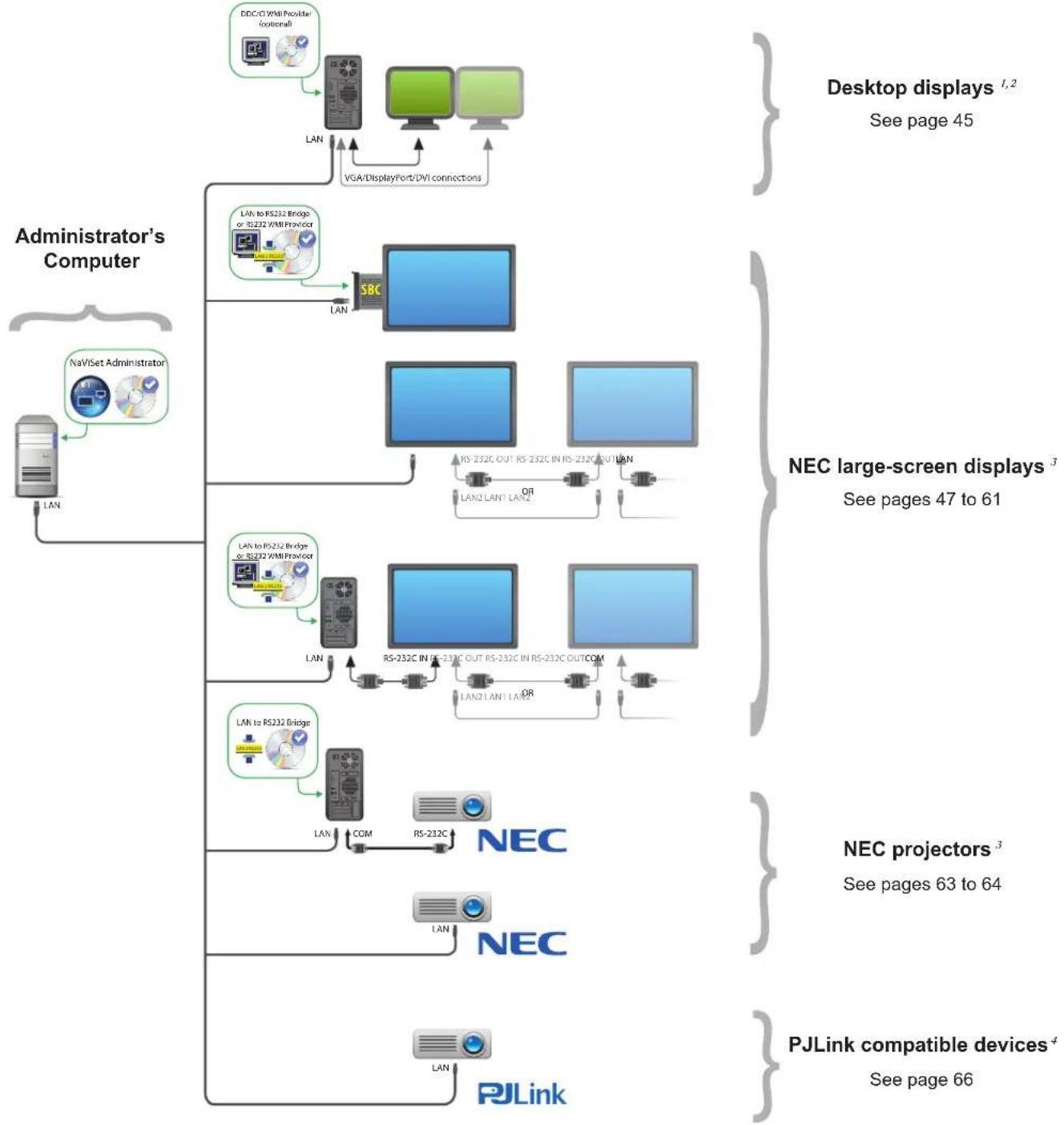
Configuration Overview
The following diagram shows the basic different configurations of devices supported by NaViSet Administrator and the related components that must be installed.
Chapter
2
User Interface Overview
Main Window
The main application window is divided into a Device Tree on the left and a Dock Window Area, containing dock windows, on the right. Multiple dock windows are stacked on top of one another and tabbed so they can be easily identified and selected.
By default NaViSet Administrator opens with two dock windows, Report Manager and Task Manager. There are several other types of function-related dock windows that use this area and all are described in the appropriate sections of this document.
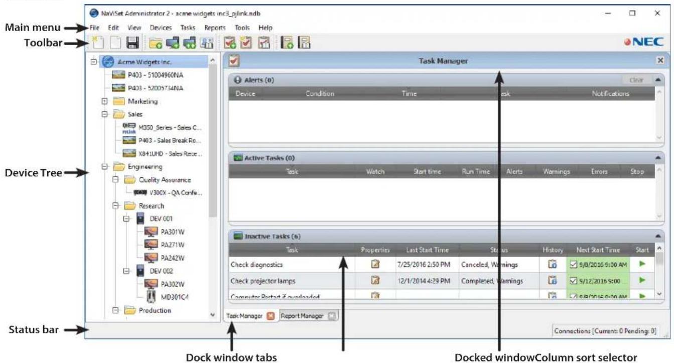
A toolbar at the top of the main window provides convenient shortcuts to many of the functions. See "Menu" on page 22 for a description of each, or mouse over the toolbar icons to see the toolbar descriptions.

A status bar at the bottom of the main window shows descriptions of menu items when selected. If enabled in the application Preferences, the status bar also shows information about connections to devices that are currently being processed and waiting to be processed. See "General Settings" on page 116 for more information.
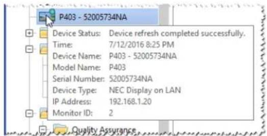
Device Tree
The Device Tree on the left of the main window represents all of the displays and computers that are in the current database. Extra information on each device in the tree is shown in tooltips, which can be seen by mousing over each item.
Note: The NaViSet Administrator application's User Interface can be displayed in English, German, French, Japanese, or Chinese (Simplified). The default language will be selected automatically based on the computer's language settings. The language can be changed via the "Language" page in the "Preferences" dialog. See "Language" on page 122 for more information.
Groups
Devices can be grouped to help organize collections of displays and computers, such as physical location (for example, by building and floor), or organizational groups (for example, "Sales" and "Marketing").
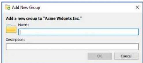
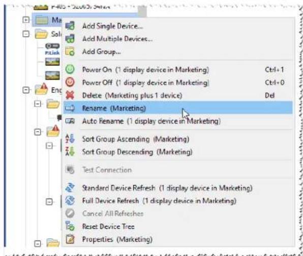
Creating Groups: Groups can be created by either selecting Add Group... from the Devices menu, or by right-clicking in the Device Tree and selecting Add Group.... Groups will be added as a new branch directly under the currently selected item in the Device Tree.
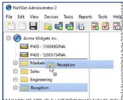
Rearranging Groups: Groups can be rearranged by clicking and dragging a Group's folder icon to another part of the Device Tree.
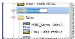
Renaming Groups: Groups can be renamed by either:
Double-clicking the group in the Device Tree
- Right-clicking a group in the device tree and selecting Rename.
- Selecting Rename from the Edit menu while the group to be renamed is currently selected.
Expanding Groups: Groups can be expanded and collapsed by clicking the icon next to the group name.
Devices
Each device in the Device Tree is represented by an icon as shown in the following table:
| Icon Description Default Device Name Format | |
| Windows computer1 | Host name |
| NEC desktop display connected to a Windows computer1 | Model name - Asset tag or Serial number2 |
| NEC medical display connected to a Windows computer1 | Model name - Asset tag or Serial number2 |
| Read-only Display: A display connected to a Windows computer with read-only connection (DDC/CI not available) or a non-NEC display.1 | Model name - Serial number |
| Single NEC large-screen display | Model name - Asset tag or Serial number2 |
| Daisy chain host: A virtual device for daisy chained NEC large-screen displays. See page 30 for a full description. | "Daisy Chain Host" |
| NEC large-screen display connected in a daisy chain | Model name (ID #)
= Monitor ID number of the connected display |
| NEC projector Model name - Asset tag | |
| PJLink Compatible Device Model name - Device name |
1 Windows version only
2 Large-screen displays and desktop displays are shipped with no asset tag set. The serial number will be used when the asset tag is blank.
Device Connection Status
The status of the network connections between NaViSet Administrator and devices can exist at different levels, and are shown in the device tree using the following indicators:
| Connection Status | Icon Description | Description |
| Normal | The device has a valid connection. The database contains the information about the device needed to fully control it. | |
| Confirmed | The device has a valid connection, but the database does not yet contain the information needed to fully control it. A Standard Refresh will be required to change the device to Normal status. | |
| Unconfirmed | Not an actual device, but a temporary placeholder for one consisting of a proposed device type and IP address or host name. A Standard Refresh will be required to confirm the device and change it to Normal status. | |
| Changed | A normal device whose connection information was recently updated due to changes made to the network settings in the device or changes to the LAN. |
Device Communications Status
Indicators on the icons represent certain states of the devices the last time they were accessed. Current and pending device activity is shown using various tree branch animations. The following table shows the various indicators:
| Communication Status | Device Indicator Containing Group Indicator | Description |
| None | No activity between the device and the system since the database was opened. | |
| Operation Pending | Pulsating yellow dot | An operation requested by the system has been placed in a queue until a connection slot becomes available. |
| Connection Retry Pending | Pulsating yellow and blue dot | The previous attempt to connect to the device was unsuccessful. The system is waiting a specified time before re-submitting the operation request into the queue. |
| Opening/Sending | Blue dot moving toward device | The system is in the process of establishing a connection and changing control settings in the device. |
| Opening/Receiving | Blue dot moving away from device | The system is in the process of establishing a connection and reading information from the device. |
| Closed/Success | The last operation between the system and the device was successful. | |
| Closed/Canceled | The last operation was canceled by user. The group icon takes precedence over Success status. | |
| Closed/Power State Warning | The last operation may not have completed successfully due to an unknown power state condition. The group icon takes precedence over Canceled status. | |
| Error | The last operation failed. The group icon takes precedence over Warning status. | |
| Refreshing | P463 - East Wall Busy progress indicator -green | A standard device refresh or a full device refresh is in progress. |
| Refresh canceling | P463 - East Wall Busy progress indicator -red | A standard device refresh or a full device refresh is in the process of being canceled. |
Adding Devices: Devices are added to the Device Tree by using either the Devices menu, or right-clicking an item in the device tree and selecting either Add Single Device... or Add Multiple Devices... See page 27 for how to add different devices.
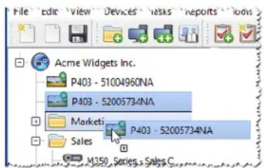
Rearranging Devices: A device can be moved between different groups by clicking the device and dragging it onto a different folder.
Renaming Devices: Devices can be renamed by either:
- Right-clicking on the device in the device tree and selecting Rename.
- Selecting Rename from the Edit menu while the device to be renamed is currently selected.

Note: Changing the Asset Tag portion of the device name in the tree will not change the Asset Tag stored in the display. To change the Asset Tag of the display, select Asset Tag from the Display Device Information list group in the controls shown in the Custom tab of the Device Properties window.
Automatically Renaming Devices: One or more devices can be renamed at a the same time automatically using the default device name format (described in the "Devices" table on page 17).
To rename one or more devices automatically, select the devices, or the groups containing the devices, and either:
- Right-click on one of the selected items and select Auto Rename Device
- Select Auto Rename Device from the Edit menu
The devices selected that require renaming will be highlighted and a message will be displayed asking for confirmation.
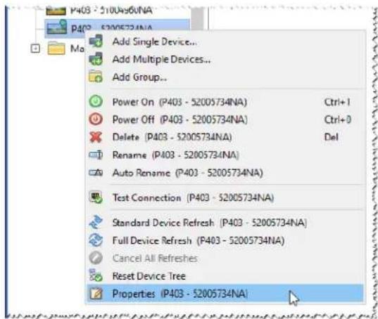
Opening a Device Properties Window: Double-clicking a device in the device tree will open the device's properties window in the dock window area. The device properties window can also be opened by right-clicking the device and
selecting Properties from the context menu.
There is no limit to the number of device properties windows that can be opened and docked at the same time.
Dock Window Area
The dock window area on the right side of the main window can contain any number of Dock Windows. By default, NaViSet Administrator opens with two docked windows, Task Manager and Report Manager. Examples of other dock windows are Device Properties Windows and the Task History Viewer.
Device Properties Windows are opened by either double-clicking a device icon in the device tree, or right-clicking a device and selecting Properties from the menu.
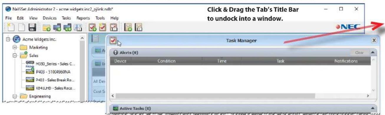
Docked windows can be moved outside the dock window area by double-clicking on the title bar, or moved to anywhere on the desktop by clicking and dragging the window's title bar. Windows that are no longer docked are called floating windows. Floating windows can be moved back into the dock window area by double-clicking on the title bar, or by clicking and dragging the title bar to move the window over the dock window area.
The ability to move dock windows to anywhere on the desktop provides a lot of flexibility, maximizes efficient use of the available desktop, and allows individual items to be given prominence on the desktop if desired.
Docked windows can be closed by clicking the close button on the tab list, or the close button in the dock window's title bar.
Both docked windows and floating windows can be hidden or shown by selecting them from the View menu.
Device Properties Window
Each Device Properties Window consists of a series of tabs which divide the device information, network settings, and numerous controls into logical categories, similar to those in the device's OSD (On Screen Display).
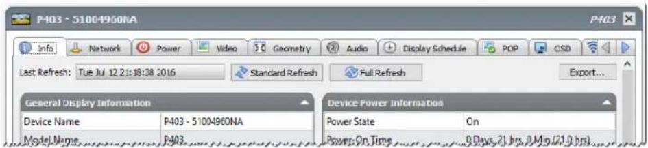
The number and types of tabs that appear for a device will depend on the capabilities of the device. Controls on the tabs allow changes to be made to the device settings in real-time. Most frequently used controls are shown on individual tabs such as Video, Audio, and Power, etc. More infrequently used controls are available on the Custom tab.
See "Controlling Devices" on page 68 for a complete description of the device property tabs.
Task Manager Window
The Task Manager window shows:
- Tasks that are currently inactive (not currently being processed/executed)
- Tasks that are currently active (being processed/executed)
Any alert conditions that have occurred while running any tasks
See "Tasks" on page 81 for more information on Tasks and the Task Manager.
Report Manager Window
The Report Manager window shows:
Inactive Reports that are not currently being run
Active Reports that are currently being run
See "Reports" on page 107 for more information on Reports and the Report Manager.
Menu
File menu
New - Creates a new database file.
Open... - Opens an existing database file.
Save - Saves the current database file.
Save As... - Saves the current database to a different file name.
Edit menu
Copy - Copies data from the currently selected table to the system clipboard.
Paste - Not currently used.
Power On - Sends the command to power on the selected display(s), or to all displays in a selected group.
Power Off - Sends the command to power off the selected display(s), or to all displays in a selected group.
× Delete - Deletes the currently selected group or device in the device tree.
- Rename - Renames the currently selected group or device(s) in the device tree.
Auto Rename Device - Renames the currently selected devices and the devices in any selected groups using the default device names.
Sort Group Ascending - Sorts the devices and groups within the currently selected group in the device tree. Does not sort sub-groups.
Sort Group Descending - Reverse sorts the devices and groups within the currently selected group in the device tree. Does not sort sub-groups.
Standard Device Refresh - Performs a Standard Refresh on the currently selected device(s) tree items.
Full Device Refresh - Performs a Full Refresh on the currently selected device(s) in the device tree.
Cancel All Refreshes - Cancel all Standard or Full Refreshes that are currently being performed on any devices.
Properties - Opens the Device Properties Window for the currently selected device in the device tree.
View menu
Status Bar - Hides or shows the status bar at the bottom of the main window.
Toolbars - Hides or shows the toolbar buttons.
Task Manager - Hides or shows the Task Manager dock window.
Report Manager - Hides or shows the Report Manager dock window.
Proof of Play Event Log - Hides or shows the Proof of Play Event Log dock window.
Devices menu
Add Single Device... - Adds a new device to the database. See "Adding Single devices" on page 27.
Add Multiple Devices... - Adds several devices to the database. See "Adding Multiple Devices" on page 33.
Add Group.... - Adds a new Group to the device tree. See "Groups" on page 16.
Test Connection - Tests the connection to a device to make sure it is accessible on the network.
Credential Library... - Opens the Credential Library. See "Credential Library" on page 78.
Tasks menu
New Task... - Creates a new task. See "About Tasks" on page 81.
Task Builder Wizard... - Creates a new task using a wizard interface.
Task Library... - Opens the Task Library. See page 82.
Proof of Play... - Opens the Proof of Play task properties dialog. See page 100.
Show/Hide Alerts - Shows or hides the Alerts list. See page 84.
Show/Hide Active Tasks - Shows or hides the Active Tasks list. See page 83.
Show/Hide Inactive Tasks - Shows or hides the Inactive Tasks list. See page 83.
Reports menu
New Report... - Creates a new Report. See "About Reports" on page 107.
Report Library... - Opens the Report Library. See page 107.
Show/Hide Active Reports - Shows or hides the Active Reports list. See page 109.
Show/Hide Inactive Reports - Shows or hides the Inactive Reports list. See page 108.
Tools menu
Preferences - Opens the application Preferences window. See "Preferences" on page 116.
Help menu
Quick Start Guide - Opens the NaViSet Administrator Quick Start Guide using the default PDF viewer. The Quick Start Guide will be displayed in the language NaViSet Administrator is currently using. See "Language" on page 122 for instructions on setting the language.
User's Guide - Opens this document using the default PDF viewer.
Check for Updates - Checks with the NEC software update system to see if a newer version is available. An Internet connection is required.
About NaViSet Administrator 2... - Displays the software and database version information.
Chapter
3
devices
Supported Devices
NaViSet Administrator supports the following basic types of networked devices:
-
Windows computers and connected display(s), both NEC and other manufacturers1
-
NEC large-screen displays
- NEC projectors
- PJLink compatible devices
A more detailed description of each of these device types is given below.
Windows computers (Windows version only)
A networked Windows computer that is using the WMI (Windows Management Instrumentation) protocol to communicate information about the connected displays. WMI support is built into Windows.
See Appendix F on page 154 for a description of WMI.
This includes the following connection types:
-
A Windows computer with one or more displays connected directly via VGA, DVI, HDMI, or DisplayPort. The included "DDC/CI WMI Provider" may be optionally installed to provide two-way communications with the displays. Any displays connected to the computer will automatically be detected and added to the device tree as branches from the computer device node.
See page 45 for details. -
A Windows computer with one or more NEC large-screen displays connected via RS232. The included "RS232 WMI Provider" must be installed on the computer.
See Appendix A on page 143 for a comparison of alternate methods of connecting large-screen displays.
See Appendix E on page 151 for more details on configuring the RS232 WMI Provider.
See page 57 for details on configuring the displays.
NEC large-screen displays
NEC large-screen displays using one of the following connection types:
An NEC large-screen display that is connected via the built in LAN connection.
See page 52 for full details.
- An NEC large-screen display that is connected via the built in LAN connection, and daisy chained to other large-screen displays via RS232 or LAN.
See page 51 for details on configuring the displays.
Note: Daisy chained large-screen displays are added as a single device using Add Single Device in the Devices menu.
- An NEC large-screen display that is connected via RS232 to a Windows computer, which is running the LAN to RS232 Bridge application.
See page 53 for details on configuring the displays. - An NEC large-screen display that is connected via RS232 to a Windows computer, which is running the NEC LAN to RS232 Bridge application, and daisy chained to other large-screen displays via RS232.
See page 53 for details on configuring the displays.
Note: Daisy chained large-screen displays are added as a single device using Add Single Device in the Devices menu.
- An NEC large-screen display with an SBC (Single Board Computer) that is connected via the LAN connection on the SBC.
See page 61 for details on configuring the displays. - An NEC large-screen display with an SBC (Single Board Computer) that is connected via the LAN connection on the SBC, and is also daisy chained to other large-screen displays via RS232. The SBC is running either the LAN to RS232 Bridge application or the RS232 WMI Provider1.
See page 59 for details on configuring the displays.
Note: Daisy chained large-screen displays are added as a single device using Add Single Device in the Devices menu.
NEC projectors
An NEC projector connected to LAN using one of the following connection types:
- An NEC projector that is connected via the built in LAN connection.
See page 63 for full details. - An NEC projector that is connected via RS232 to a Windows computer that is running the LAN to RS232 Bridge application.
See page 64 for full details.
PJLink compatible devices
A PJLink compatible device connected directly to the LAN.
See page 66 for full details.
Adding Devices
Devices can be added to the device tree individually or multiples added simultaneously. When adding a large number of devices it is recommended to use the multiple devices methods.
One exception is when adding multiple large-screen displays daisy chained via RS232. In this case all of the displays are added simultaneously as one connection device, known as the "Daisy Chain Host", and must be added as a single device.
See "About Daisy Chain Hosts" on page 30.

Note: For the best results when adding devices, the computers and/or displays should be powered on. This will ensure all of the information that is necessary for NaViSet Administrator to provide full functionality is read and stored in the database.
Adding Single devices
To add single devices to the device tree use either the Devices menu, or right-click an item in the device tree and select Add Single Device..., or click the toolbar button. The Add a device to dialog will appear.
All devices added using this method must be powered on and accessible.

Note: Devices added using this method will be inserted in the first valid row below the currently selected item, indicated by the icon.
- "Adding a single Windows computer on LAN (WMI) (Windows version only)" on page 27
- "Adding NEC large-screen display(s) connected to LAN" on page 28
- "Adding a single NEC projector connected to LAN" on page 30
- "Adding a single PJLink device connected to LAN" on page 32
Adding a single Windows computer on LAN (WMI) (Windows version only)
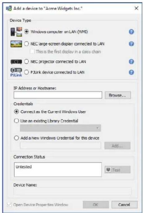
Select Windows computer on LAN (WMI).
Enter the computer's network name or IP address, or click Browse... to view and select a computer currently available on the LAN.

Note: It may take several seconds after clicking the Browse... button for the dialog to appear while the network is enumerated. Only computers that are currently available on the LAN will be shown.
If you are currently logged in as a domain administrator and have credential access to the remote computer, then select Connect as the Current Windows User.
If the remote computer requires different credentials, select either Use an existing Library Credential, if the credentials have already been added to the Credential Library, or Add a New Windows Credential for this device to enter new
credentials and optionally save to the Credential Library. See page 78 for more information on using the Credential Library.
Click the Test button to confirm the network connection.
If the connection is successful, then the computer's name will be automatically entered into the Device Name. The Device Name is the name used to identify the computer in the device tree and can be edited if desired before it is added to the device tree, or later on by renaming the device in the device tree.
If the test connection is successful, click OK to add the Windows computer to the device tree. Any displays connected to the Windows computer will be detected automatically and added to the device tree under the computer node.
Troubleshooting
If an error occurred when performing the Test operation see the troubleshooting steps "Problem: Unable to connect to a Windows Computer via WMI" on page 141.
Adding NEC large-screen display(s) connected to LAN
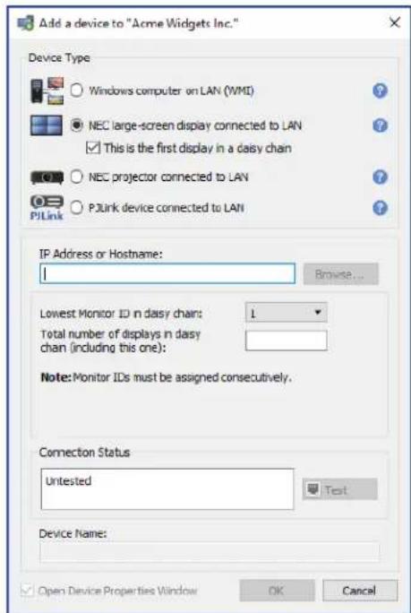
Select NEC large-screen display connected to LAN.
Enter the IP address or hostname of the large-screen display, or click Browse... to view and select a large-screen display currently available on the LAN. If the LAN to RS232 Bridge is being used, enter the computer name or IP address of the Windows computer to which the large-screen display is connected.
Browse for NEC Large-Screen Display Dialog
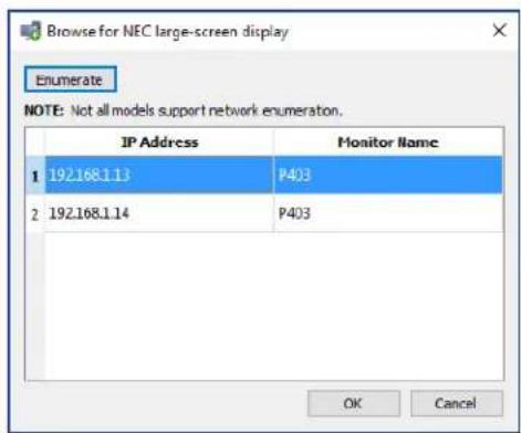
If using the Browse function, the Browse for NEC Large-Screen Display dialog will attempt to automatically detect any large-screen displays that are available on the LAN.
- Click the Enumerate button to start the detection process. Any detected displays will be listed by IP address and Model Name.
- Select the desired display in the list and click OK.
Not all large-screen display models support the automatic network enumeration feature.
If the Monitor ID of the display is not known, leave Auto Detect selected in the Monitor ID list, otherwise select the Monitor ID of the display as configured on the display's OSD.
If the large-screen display connected to LAN also has other displays daisy chained from it, then select This is the first display in a daisy chain and select the lowest Monitor ID in the daisy chain. Next, enter the Total number of displays in the daisy chain.

Note: When using daisy chains, the Monitor IDs must be numbered uniquely and sequentially.
Click Test to confirm the network connection and display detection.
If the connection for a single display is successful, the model name will be automatically entered into the Device Name using the default device naming format. If the connection for multiple displays is successful, "Daisy Chain Host" will be automatically entered as the device name. The Device Name is the name used to identify the display in the device tree, and can be edited if desired before it is added to the device tree, or later on by renaming the device in the device tree.

Note: Changing the Asset Tag portion of the device name will not change the Asset Tag stored in the display. To change the Asset Tag of the display, select Asset Tag from the Display Device Information list group in the controls shown in the Custom tab of the Device Properties window.
If the test connection is successful, click OK to add the display(s) to the device tree.
Troubleshooting
If an error occurred when performing the Test operation, see the troubleshooting steps "Problem: Unable to communicate with an NEC large-screen display" on page 141.
About Daisy Chain Hosts
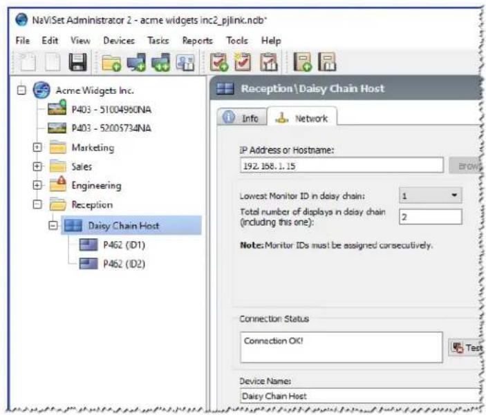
When daisy chained large-screen displays are added, a virtual device called a "Daisy Chain Host" is created in the device tree with the icon. All of the actual daisy chained displays are branches from this device with the icon
The Daisy Chain Host device is a placeholder for the connectivity information for the entire daisy chain as follows:
- IP Address or Hostname of the LAN connection on the first display on the daisy chain
- Lowest Monitor ID in the daisy chain
- Total number of displays in the daisy chain
The Monitor IDs for each display will be included in parenthesis in the device names.
Adding a single NEC projector connected to LAN
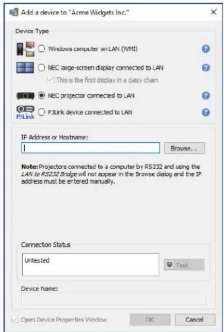
Select NEC projector connected to LAN.
Enter the IP address or hostname of the projector, or click Browse to automatically detect projectors that are connected directly to the LAN.
If the LAN to RS232 Bridge is being used, enter the computer name or IP address of the Windows computer.

Note: Projectors connected to a computer by RS232 and using the LAN to RS232 Bridge are not be able to be detected using the Browse function. Not all projector models support the automatic network enumeration feature. In both cases the projector or computer IP address / computer name must be entered manually.
Browse for NEC Projector Dialog
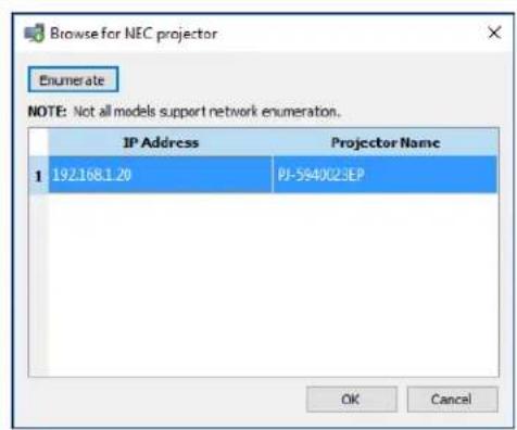
If using the Browse function, the Browse for NEC Projector dialog will attempt to automatically detect any projectors that are available on the LAN.
- Click the Enumerate button to start the detection process. Any detected projectors will be listed by IP address and Projector Name.
- Select the desired projector in the list and click OK.
Not all projector models support the automatic network enumeration feature.
Click Test to confirm the network connection.
If the connection is successful, the model name of the projector will be automatically entered into the Device Name together with its Asset Tag text (also known as Projector Name). The Device Name is the name used to identify the projector in the device tree. If desired, it can be edited before it is added to the device tree or later on by renaming the device in the device tree.
If the test connection is successful, click OK to add the projector to the device tree.

Note: Changing the Asset Tag / Projector Name portion of the device name will not change the Asset Tag / Projector Name stored in the projector. To change the Asset Tag / Projector Name of the projector, select Asset Tag from the Display Device Information list group in the controls shown in the Custom tab of the Device Properties window.
Troubleshooting
If an error occurred when performing the Test operation, see the troubleshooting steps "Problem: Unable to communicate with an NEC projector" on page 141.
Adding a single PJLink device connected to LAN
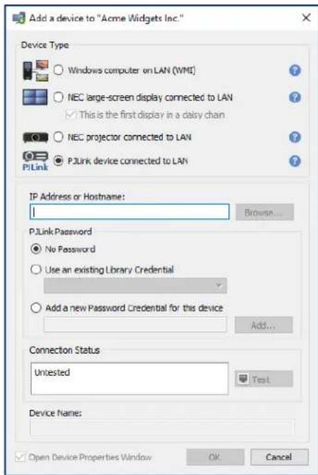
Select PJLink device connected to LAN.
Enter the IP address or hostname of the PJLink device.
If the device requires a password, select either Use an existing Library Credential, if the credentials have already been added to the Credential Library, or Add a new Password Credential for this device to enter new credentials and optionally save to the Credential Library. See page 78 for more information on using the Credential Library.
Click the Test button to confirm the network connection.
If the connection is successful, then the device's name will be automatically entered into the Device Name field. The Device Name is the name used to identify the device in the device tree and can be edited if desired before it is added to the device tree, or later on by renaming the device in the device tree.
If the test connection is successful, click OK to add the PJLink device to the device tree.
Adding Multiple Devices
If there are several devices to be added, adding them using the Add Multiple Devices dialog is easier and more efficient than adding one by one using the Add Single Devices function.
To add multiple devices to the device tree, use either the Devices menu, or right-click an item in the device tree and select Add Multiple Devices..., or click the toolbar button. The Add Multiple Devices dialog will appear. Select the type of display and connection to be added from the tabs at the top.

Note: Large-screen displays that are daisy chained via RS232 must be added as a single device, and cannot be added using Multiple Devices. The only exception is when using the RS232 WMI Provider1, which will automatically add all connected displays when the host computer is added.
The Add Multiple Devices dialog consists of a tab page for each supported device type:
-
"Importing multiple Windows computers (WMI) (Windows version only)" on page 37^1
-
"Importing multiple NEC large-screen displays" on page 40
- "Importing multiple NEC projectors" on page 41
- "Importing multiple PJLink devices" on page 43
Begin by selecting the tab for the type of device to be added.
The procedure for adding multiple devices can be divided into 3 main steps:
- Import a list of potential devices
- Verify the devices to add to the device tree
- Choose a location in the tree and add the devices
Importing Devices - Device Validation mode

There are numerous advantages to querying the connections for device information:
- New devices will be pre-validated, so they will be configured and ready to use as soon as they are added to the tree.
- The correct default device names will be assigned automatically. Otherwise only the IP addresses or host names can initially be used for the device names.
The imported devices table will include information about the devices to make them easily identifiable.
The system will have the information needed to check the device tree for any conflicts with existing devices, report the conflicts and propose how to resolve them.
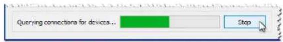
Querying a large number of devices can be time consuming and the user interface is disabled while the queries are running. However, the process can be stopped at any time by clicking the Stop button next to the progress indicator. All items imported up to that point will remain in the table.
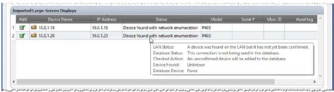
Example: The following images show how the same device appears in the table with and without Validation:
Validation Mode checked - The display has been validated and assigned the proper default device name. The model name, serial number, monitor ID, and asset tag are now known. The display is a confirmed NEC product and will be ready for use as soon as it is added to the tree.
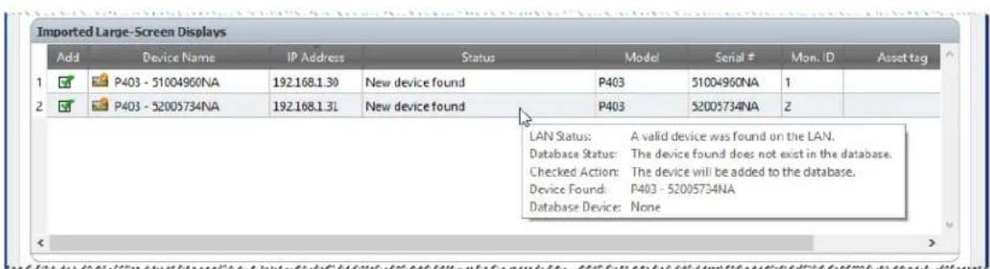
Validation Mode unchecked - Nothing is known about the network device at this IP address, if there is one. The IP address is used as the device name. This IP address will be added to the tree as an unconfirmed NEC large-screen display.
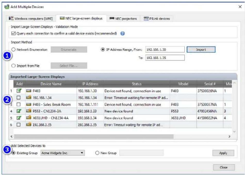
Step 1: Importing Devices
Importing devices involves populating the Imported Devices table with a list of potential devices to be added.
Validation Mode - When the Query each connection to confirm a valid device exists box is checked, a test connection will be performed on each device as it is being imported.
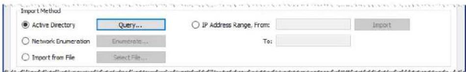
Import Method - There are several methods provided for establishing the list of devices to import. These methods vary depending on the types of devices, and are explained in detail in the following sections:
- Windows computers1 - See "Importing multiple Windows computers (WMI) (Windows version only)" on page 37.
- NEC large-screen displays - See "Importing multiple NEC large-screen displays" on page 40.
- NEC projectors - See "Importing multiple NEC large-screen displays" on page 40.
Step 2: Verifying the Devices
Once the list of potential devices has been imported, the Imported Devices table is used to select the devices to be added to the device tree.
The Imported Devices table has the following columns:
Add - Contains the checkbox used to either include or exclude the device. Typical connections that were detected without conflicts will be checked by default, whereas any uncommon connection conditions will not be checked.

Note: A context menu, providing operations to check or uncheck multiple devices at a time, can be opened by right-clicking on the device list.
Device Name - For new devices, this is the device icon and name that will appear in the tree if the device is added. For existing devices this is the name of the device used in the tree. The device name can be edited in place by either double-clicking on it, or right-clicking and selecting Edit Device Name from the context menu.
IP Address or Host Name - If the devices were imported by IP address, then this column will be named IP Address and will contain the IP addresses. Similarly, if the devices were imported by host name, then this column will be named Hostname and will contain the host names.
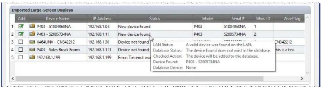
Status - Shows the import status of the device. A detailed tooltip for each device will contain up to 5 pieces of additional information about the status of the device and its connection:
LAN Status - The result of the test connection (available only when Validation Mode is selected).
- Database Status - Reports if this connection is being used by another device in the tree, or if the device found on the LAN already exists in the tree (available only when Validation Mode is selected).
- Checked Action - Describes how the device will be added to the tree, or any connection changes that will take place.
Device Found - The default device name of the device found on the LAN at this connection (available only when Validation Mode is selected).
- Database Device - The device name of a device in the tree that is already using this connection.
- Model (large-screen displays and projectors only) - The model name read from the device.
- Serial # (large-screen displays and projectors only) - The serial number read from the device.
- Mon. ID (large-screen displays only) - The monitor ID of the display.
Asset Tag (large-screen displays and projectors only) - The asset tag string read from the device.
Step 3: Adding the Devices to the Device Tree
Before adding the selected devices to the tree, the destination group can be verified and changed if necessary.

Select Existing Group and choose a group from the drop-down list to add the devices to an existing group.
To create a new group, select New Group and enter a name for the group. The new group will be added to the bottom of the tree as a child of the top group (My Network).

Note: The insertion position will be indicated with a icon in the device tree.
Once the destination group is established, click Apply to add the devices to the tree.
Refreshing Device Information
Immediately after clicking the Apply button, the following message box will be displayed:
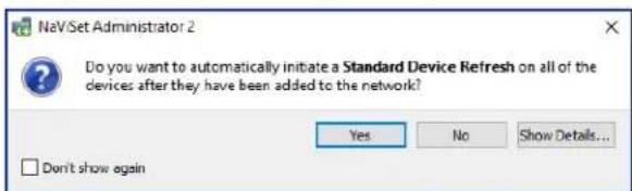
Select Yes to automatically start a Standard Device Refresh on all of the devices once they have been added. Performing a refresh at this point ensures that the resulting devices will be fully configured for all NaViSet Administrator operations.
Before choosing not to perform a refresh at this point, consider:
Desktop displays attached to Windows computers will not appear in the device tree until a standard refresh is performed.
A Standard Device Refresh will eventually be required to have full control over the device.
- Attempting to manage the device in NaViSet Administrator will likely result in various warning messages until a standard refresh is performed.
Although performing a refresh on a large number of devices can be time-consuming, refreshes that are in progress can be canceled and re-run at a later time as needed.
The devices are removed from the Imported Devices table as they are being added to the device tree. Once complete, only the unselected devices will remain. This procedure can be repeated to import and add additional devices without closing the dialog.
Importing multiple Windows computers (WMI) (Windows version only)
Windows computers can be imported in several different ways:
Method 1: "Active Directory"
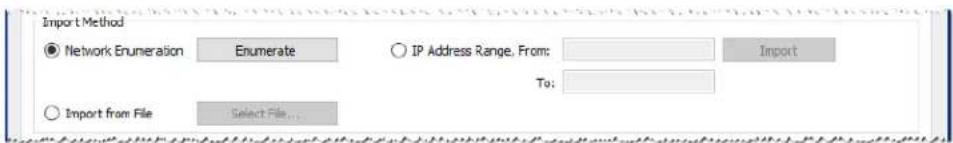
Method 2:"Network Enumeration"
Method 3: "Import from File"
Method 4: "IP Address Range"
When computers are imported using any of the above methods, a Credentials dialog will be displayed. Access credentials to the computer must be specified using one of the following options:
The currently logged in user's credentials
An existing credential from the Credential Library (see page 78 for more information)
- A device-specific credential to be entered and optionally added to the Credential Library
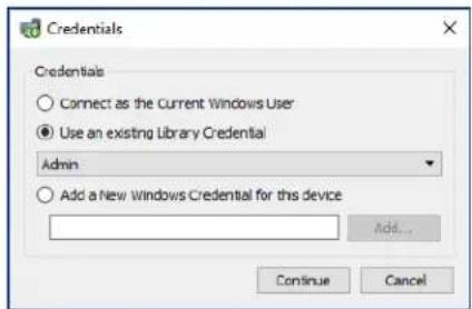

Note: The same access Credentials are applied to all of the computers imported together. To use different credentials on different computers, add them separately by repeating this procedure.
>Method1:Addcomputersusing"ActiveDirectory
If the Windows network is part of a domain with an Active Directory server, then the server can be queried to retrieve a list of computer names in the domain. This is a fast and reliable way to add computers. The names of computers that are currently not available on the network can be retrieved via the Active Directory.
Select Active Directory and click the Query... button to open the Active Directory Query dialog.
Active Directory Query Dialog
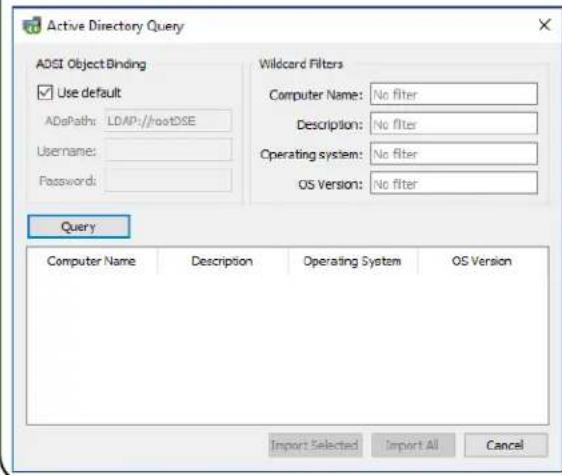
ADSI Object Binding - Defines the address and credentials used to connect to the Active Directory Server. Select Use Default unless connecting to a different domain or credentials than the default.
Query - Sends a query to the Active Directory Server and lists the results.
Wildcard Filters - Allows the query results to be filtered by applying text wildcards to the Computer Name, Description, Operating System, and OS Version columns.
Import Selected and Import All -Adds the items to the table, after the access credentials have been specified.
>Method 2:Add computers using "Network Enumeration"
Windows computers that are currently online on the LAN can be enumerated and added in the same way network devices are found and shown in the Windows Network list. A computer must typically be running and have been connected to the LAN for several minutes in order to appear in the Network Enumeration list. The network enumeration can take up to several minutes to perform depending on the number of devices on the network.
Select Network Enumeration and click the Enumerate... button to open the Network Enumeration dialog.
Network Enumeration Dialog
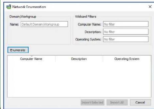
Name: - Defines the domain or workgroup to enumerate. The current domain/workgroup will be used if none is entered.
Enumerate - Starts the network enumeration process and lists the results.
Wildcard Filters - Allows the query results to be filtered by applying text wildcards to the Computer Name, Description, and Operating System.
Import Selected and Import All -Adds the items to the table, after the access credentials have been specified.
>Method 3:Add computers using "Import from File"
A list of IP addresses and/or computer names can be imported from any of the following file types:
A column of an Excel spreadsheet file
A delimited text file
Another NaViSet Administrator 2 database file
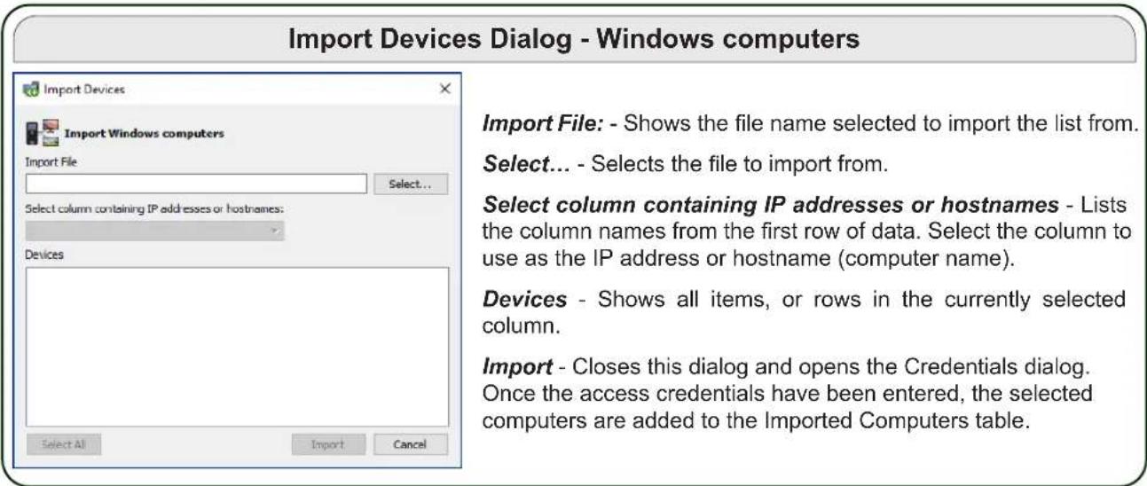
Select Import from File and click the Select File... button to open the Import Devices dialog.
Method 4: Add computers using "IP Address Range"
A range of computer IP addresses can be specified and added. Enter the lower IP range in From, and the upper range in To.

Click Import to open the Credentials dialog. Once the access credentials have been entered, all of the IP addresses in the specified range will be added to the Imported Computers table.
Importing multiple NEC large-screen displays
Multiple NEC large-screen displays can be imported in three different ways:
Method 1: "Network Enumeration"
Method 2: "Import from File"
Method 3: "IP Address Range"
Note: The Monitor ID of each display is detected automatically if the display is reachable.
Note: This is not the proper procedure for adding multiple displays that are daisy chained using RS232. For these configurations, the entire daisy chain must be added as a single Daisy Chain Host device via the Add Single Device dialog.
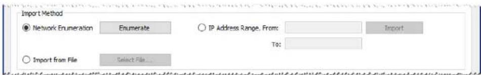
Method 1:Add NEC large-screen displays using "Network Enumeration"
Newer models of NEC large-screen displays that are connected directly to LAN are capable of being automatically identified. A special identification message will be broadcast and list any displays that responded.
Method 2:Add NEC large-screen displays using "Import from File"
A list of IP addresses can be imported from any of the following file types:
A column of an Excel spreadsheet file
A delimited text file
Another NaViSet Administrator 2 database file
Select Import from File and click the Select File... button to open the Import Devices dialog.
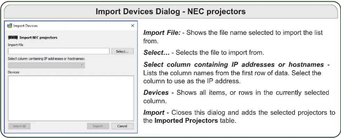
Import Devices Dialog - NEC large-screen displays
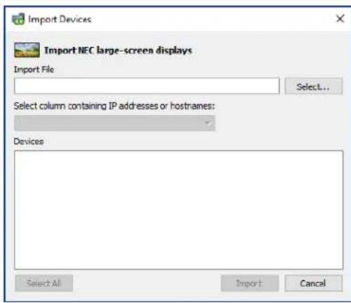
Import File: - Shows the file name selected to import the list from.
Select... - Selects the file to import from.
Select column containing IP addresses or hostnames - Lists the column names from the first row of data. Select the column to use as the IP address.
Devices - Shows all items, or rows in the currently selected column.
Import - Closes this dialog and adds the selected displays to the Imported Large-Screen Displays table.
Method 3: Add NEC large-screen displays using "IP Address Range"
A range of display IP addresses can be specified and added. Enter the lower IP range in From, and the upper range in To.

Click Import to add all of the IP addresses in the specified range to the Imported Large-Screen Displays table.
Importing multiple NEC projectors
Multiple NEC projectors can be imported in the following different ways:
Method 1: "Network Enumeration"
Method 2: "Import from File"
Method 3: "IP Address Range"
>Method 1:Add NEC projectors using "Network Enumeration"
Many models of NEC projectors that are connected directly to LAN are capable of being automatically identified. A special identification message will be broadcast and list any projectors that responded. Any projectors that were identified will be added to the list below.

Note: Projectors connected to a computer by RS232 and using the LAN to RS232 Bridge are not be able to be detected using the Network Enumeration function. Not all projector models support the automatic network enumeration feature.
>Method 2:Add NEC projectors using "Import from File"
A list of IP addresses can be imported from any of the following file types:
A column of an Excel spreadsheet file
A delimited text file
Another NaViSet Administrator 2 database file
Select Import from File and click the Select File... button to open the Import Devices dialog.
Method 3: Add NEC projectors using "IP Address Range"
A range of display IP addresses can be specified and added. Enter the lower IP range in From, and the upper range in To.

Click Import to add all of the IP addresses in the specified range to the Imported Projectors table.
Importing multiple PJLink devices
Multiple PJLink devices can be imported in the following different ways:
Method 1: "Import from File"
Method 2: "IP Address Range"

>Method 1:Add PJLink devices using "Import from File"
A list of IP addresses can be imported from any of the following file types:
A column of an Excel spreadsheet file
A delimited text file
Another NaViSet Administrator 2 database file
Select Import from File and click the Select File... button to open the Import Devices dialog.
Import Devices Dialog - PJLink Devices
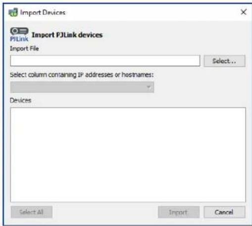
Import File: - Shows the file name selected to import the list from.
Select... - Selects the file to import from.
Select column containing IP addresses or hostnames - Lists the column names from the first row of data. Select the column to use as the IP address.
Devices - Shows all items, or rows in the currently selected column.
Import - Closes this dialog and adds the selected devices to the Imported PJLink Devices table.
>Method 2:Add PJLink devices using "IP Address Range"
A range of PJLink device IP addresses can be specified and added. Enter the lower IP range in From, and the upper range in To.

Click Import to add all of the IP addresses in the specified range to the Imported PJLink Devices table.
Chapter
4
Configuring devices
This chapter covers how to configure the various supported devices so that NaViSet Administrator can successfully connect to, query, and control them.
Desktop Displays (Windows version only)
For desktop displays, see:
"Desktop display(s) connected to a Windows Computer" on page 45
NEC Large-Screen Displays
Identify the type of connection available on the model of NEC large-screen display being used, by referring to "Desktop display(s) connected to a Windows Computer" on page 45. This section explains the different types of connections and daisy chain options available.
For specific information on each type of connection available on NEC large-screen displays, see:
- "NEC large-screen display(s) using direct LAN connection" on page 51
- "NEC large-screen display(s) with LAN hub using direct LAN connection" on page 52
- "NEC large-screen display(s) using LAN to RS232 Bridge" on page 53
- "NEC large-screen display(s) with LAN hub using LAN to RS232 Bridge" on page 55
- "NEC large-screen display(s) using RS232 WMI Provider" on page 57
- "NEC large-screen display(s) with SBC and dual LAN connections" on page 59
- "NEC large-screen display with SBC and single LAN connection" on page 61
NEC Projectors
For NEC projectors, see:
- "NEC projector using direct LAN connection" on page 63
- "NEC projector connected via Windows Computer to LAN" on page 64
PJLink Devices
For PJLink compatible devices, see:
- "PJLink compatible device using direct LAN connection" on page 66
Desktop display(s) connected to a Windows Computer
Configuration Overview
One or more desktop displays connected to a Windows computer with a standard video cable. The "DDC/CI WMI Provider" can be optionally installed on the computer to provide advanced information for all displays and is required for two way control of NEC displays.
Configuration Features
Basic information about the main display, such as Model Name and Serial Number, without requiring the DDC/CI WMI Provider to be installed.
Communications with the display(s) via the video graphics card and standard video cables, so no additional cabling is required.
Supports WMI Scripting when using the "DDC/CI WMI Provider". See Appendix G on page 155.
Adding device(s) to NaViSet Administrator
Select the device type Windows computer on LAN (WMI) when adding devices. See the restrictions below.
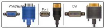
Connection Diagram
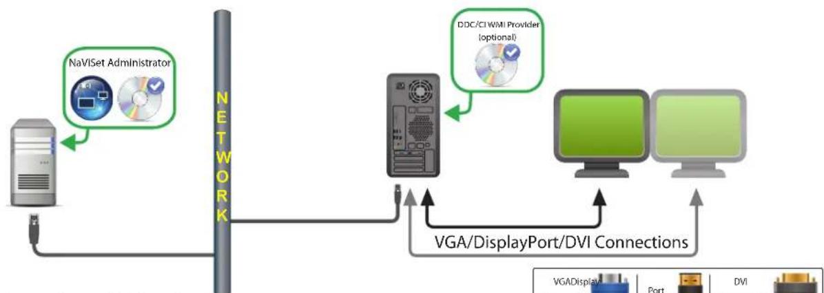
Note: Optional connections and devices shown in gray.
Restrictions
Remote connection to a Windows computer supported on Windows version of NaViSet Administrator only.
KVM (Keyboard / Video / Mouse) switches, splitters, and long video cables (>3m) are not supported.
Support in the video graphics card driver is required for two way communications. Always update to the latest video drivers available from the video graphics card vendor. Video drivers included by default in Windows might not provide communications support.
- DDC/CI WMI provider required for detailed information and information from additional displays other than the primary display.
See "Windows Computer on LAN connections via WMI" on page 46 for important information about configuring WMI.
Notes
Basic display information available for both NEC and third party desktop displays is available.
- Most newer graphics cards supported. See the DDC/CI WMI Provider README for latest support information.
The DDC/CI WMI Provider can communicate via USB to NEC PA series of desktop displays.
Support for Windows computer Shutdown, Restart, Wake-on-LAN, and monitoring of computer parameters is provided automatically.
Control of NEC large-screen displays is supported by DDC/CI but with some limitations. See Appendix A on page 143 for details.
The DDC/CI WMI Provider cannot be installed at the same time as the RS232 WMI Provider.
Windows Computer on LAN connections via WMI
When connecting to remote Windows computers via WMI, the following important points must be verified to ensure a successful connection:
- The Windows user account used to access the remote computer must have sufficient access privileges to WMI (specifically the ROOT\CIMV2 namespace). Typically Administrator accounts have sufficient access privileges by default.
The password for the account used to access the remote computer must not be a blank password. - The Windows Firewall on both the local and remote computers must allow remote access to WMI. The default Windows Firewall settings typically block access to WMI, thus preventing remote access to a computer.
The Windows Firewall settings for WMI can also be manually changed from the Windows Control Panel, as shown below, in order to allow remote access:
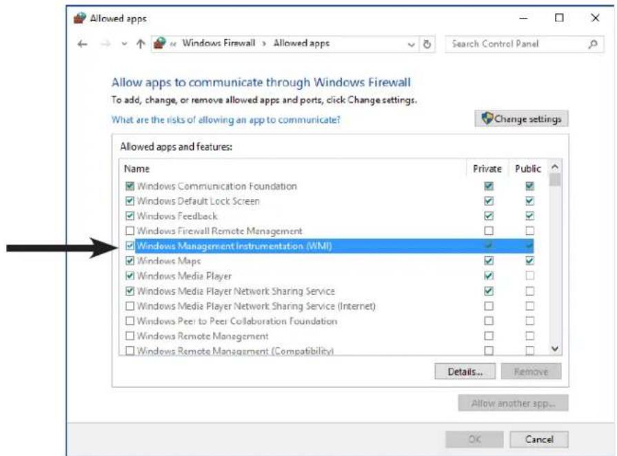
If the Windows computers on the network are part of a Windows Workgroup and not a Domain, the default UAC (User Account Control) security settings will not allow access to WMI, even if the Firewall is disabled. Installing the DDC/CI or RS232 WMI Providers on the computer will automatically configure the security settings to allow access.
Configuring and connecting NEC large-screen displays
NEC large-screen displays can be connected to the network in a variety of ways using RS232 or LAN, depending on the model.
Also, depending on the model, displays can be daisy chained together using RS232 or LAN cables. Daisy chaining displays can simplify cable wiring, and allows more than one display to be controlled from one access connection, as well as minimizing the lengths and number of cable runs.
The following table shows the types of daisy chains available depending on the connection configuration of the display model being used.
| Display connection configuration | Connection description Daisy | chain type Input conne | ction from network to first display in daisy chain |
| RS-232C RS-232C IN OUT | RS-232C IN and OUT RS232 | \( RS232^1 \) | |
| RS-232C RS-232C LAN IN OUT | RS-232C IN, OUT, and LAN RS | 232 | LAN or RS232 (\( selectable \))1 |
| LAN1LAN2 RS-232C | RS-232C (IN), LAN 1, and LAN2 LAN | LAN or \( RS232^1 \) | |
| RS-232C LAN | RS-232C (IN) and LAN Not available | LAN or \( RS232^1 \) (Daisy chaining is not available for this display configuration) |
1 RS232 input connection from network requires a Windows computer
To determine the correct display connection configuration for the display models being used:
- Look at the physical connections on the display.
Refer to the display's User's Manual.
About Monitor IDs
Each display has a Monitor ID number that is used to individually identify and address it when used in a daisy chain.
Each display in a daisy chain must have a unique Monitor ID (except for LAN daisy chain connections where the Auto ID function is not used).
- The Monitor ID is configured via the display's OSD (all displays) or in the embedded web page (LAN displays).
- Models that support LAN daisy chains can also have the Monitor ID set automatically using the Auto ID function in the OSD, or via the embedded webpage. See "Using the Auto ID function with a LAN daisy chain" on page 50 and the display User's Manual for more information.
The Monitor ID configured in NaViSet Administrator must match the Monitor ID on each display.
Monitor IDs also allow displays to be individually controlled from a single IR remote control. See the display User's Manual for more information on using the IR Remote with multiple displays.
The following sections describe each of the 3 basic connection types for connecting multiple NEC large-screen displays:
- Connecting Directly to LAN
- Connecting via an RS232 Daisy chain
- Connecting via a LAN Daisy chain
Connecting Directly to LAN
| Supported display connection configurations | ||
| RS-232C IN RS-232C LAN OUT | RS-232C IN, OUT, and LAN | |
| LAN1LAN2 RS-232C | RS-232C (IN), LAN 1, and LAN 2 | |
| RS-232C LAN | RS-232C (IN) and LAN (daisy chain not supported) | |
Models that have an RJ45 LAN connection can be individually connected directly to a LAN via a hub or switch instead of daisy chaining displays together. This may require more wiring since each display is individually connected directly to a central LAN hub or switch. The advantages of using this method is that communications to other displays will still function even if:
- A display is removed from the video wall without bridging the daisy chain.
- A display loses AC power or is turned off via the display's main power switch.
A display fails.
There is a fault in cabling to an individual display. - A display enters standby power mode and the LAN POWER setting is set to OFF (models that support LAN daisy chain only).
Important points to note:
Each display must have a unique IP address.
- Since each display is addressed by the combination of IP address and Monitor ID, each display can have the same or unique Monitor IDs.
Connecting via an RS232 Daisy chain
| Supported display connection configurations | ||
| RS-232C IN RS-232C OUT | RS-232C IN and OUT | |
| RS-232C IN RS-232C OUT LAN | RS-232C IN, OUT, and LAN | |
Models that have two RS232 connections (not including any RS232 connections on OPS devices), support RS232 daisy chaining. The connection labeled IN is the input to the display from a host computer or previous display in the daisy chain. The other connection labeled OUT is the output to connect to the IN on the next display in the daisy chain.
Important points to note:
- When using RS232 to connect displays using a daisy chain, each display on the chain must have a unique Monitor ID (set via the display's OSD).
- Displays must be connected using an RS232 serial NULL modem cable (also known as a "crossover" cable).
-
The first display in the daisy chain can be connected to a host computer either via RS232, or by LAN if the model has an RJ45 LAN connection (not including any RJ45 LAN connections on OPS devices). When connected via LAN, the first display can forward commands received over LAN to other displays in the RS232 daisy chain.
The RS232 connection from a host computer must connect to the RS232 IN on the first display. -
Communications via both LAN and RS232 are not supported at the same time. The type of communications link used to connect to the display (RS-232C or LAN) must be selected in the EXTERNAL CONTROL option of the OSD.
Connecting via a LAN Daisy chain
Supported display connection configurations
LAN1LAN2

BS-232G

RS-232C (IN), LAN1, and LAN2
Models that have two RJ45 LAN connections (not including any RJ45 LAN connections on OPS devices) support LAN daisy chaining. The RJ45 LAN connection labeled LAN1 should be used as an input to the display from the network. The other LAN connection labeled LAN2 is the output to connect to the LAN1 on the next display in the daisy chain.
The display functions as a two port LAN hub for LAN traffic.
Important: The LAN hub function only works when AC power is applied to the display and the LAN interface is powered on. By default the LAN POWER setting is set to turn off when the display enters a standby power mode. This will prevent communications with other devices along the LAN daisy chain. To prevent this, change the LAN POWER setting to ON via the OSD. This setting can also be automatically set to ON when the device is added to NaViSet Administrator if the preference setting is selected - see "Devices" on page 121.
Displays in a LAN daisy chain that are connected to a LAN network can be addressed in two different ways:
>Option 1-Direct (recommended):
Each display in a LAN daisy chain can also be added to NaViSet Administrator as an individual NEC large-screen display, rather than as part of a daisy chain, by adding each display by its IP address and Monitor ID.
NaViSet Administrator will communicate directly to each display via its IP address.
>Option 2-Via Translation:
The first display in a LAN daisy chain can act as a host for commands it receives for any of the other displays further along the daisy chain. It will translate and forward to the relevant display any commands received via the LAN2 connection sent to its IP address, but with Monitor IDs for other displays in the daisy chain.
In order to do this, the Auto ID function must be successfully performed on the first display. The Auto ID function is used to identify all displays along the LAN daisy chain and assign them sequential Monitor IDs. The first display in the LAN daisy chain stores a table of the IP addresses and assigned Monitor IDs for all of the other displays in the daisy chain.
To use this type of addressing, the displays must be added using the Add Single Device dialog and selecting This is the first display in a daisy chain. See "Adding NEC large-screen display(s) connected to LAN" on page 28 for more information.
Important: Using direct addressing for each NEC large-screen display is highly recommend when using NaViSet Administrator since it allows simultaneous communications with multiple displays, rather than having to wait for the first display to process communications for each display in turn within the daisy chain.
Therefore, when adding NEC large-screen displays that are daisy chained via LAN, it is recommended to add them individually by IP address rather than treating them as a daisy chain.
See the following for more information on using the Auto ID function.
Using the Auto ID function with a LAN daisy chain
- The LAN2 RJ45 (output) of a display must connect to the LAN1 RJ45 (input) on the next display in a daisy chain.
Each display must have a unique IP address assigned.
Network hub devices must not be used to create multiple branches of displays along the LAN daisy chain. All displays must be connected sequentially.
The LAN2 RJ45 of the last display in the daisy chain must not be connected back to the network (do not form a network loop).
Monitor IDs are automatically assigned sequentially starting at Monitor ID 1.
Monitor IDs are assigned based on the physical LAN cable connection order - not the IP address assignment order. - All displays must be powered on when performing the Auto ID function.
The Auto ID function should only be performed from the first display in the daisy chain. Do not perform Auto ID from displays further along the daisy chain.
NEC large-screen display(s) using direct LAN connection
Supported Display Connection Configurations
| RS-232C IN OUT LAN | RS-232C IN, OUT, and LAN |
| RS-232C LAN | RS-232C (IN) and LAN (daisy chain not supported) |
Configuration Overview
Large-screen display connected directly to the LAN and using one IP address.
Configuration Features
Additional displays can be daisy chained from the LAN-connected display via RS232 (if supported).
- Operates without a computer.
Adding device(s) to NaViSet Administrator
Select the device type NEC large-screen display connected to LAN when adding devices. See the restrictions below.
Connection Diagram
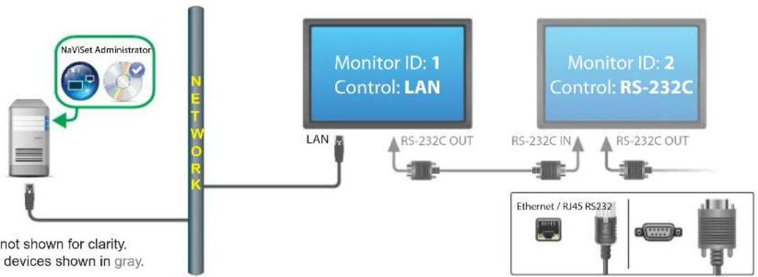
Note: Video connections not shown for clarity. Optional connections and devices shown in gray.
Restrictions
Each display on the daisy chain must have a unique Monitor ID.
Monitor IDs for daisy chained displays do not have to start at 1, but must be consecutive.
The first display must be configured to use LAN. Others must be configured to use RS-232C control.
RS-232C cables must be crossover / NULL modem type.
If displays are daisy chained, they must be added to the device tree using Add Single Device... and selecting This is the first display in a daisy chain.
RS232 splitters or Y connections are not permitted on any connection.
NEC large-screen display(s) with LAN hub using direct LAN connection
Supported Display Connection Configurations

Configuration Overview
Large-screen display with internal LAN hub connected directly to the LAN.
Configuration Features
Additional displays can be daisy chained from the first display via LAN using the internal LAN hub.
- Operates without a computer.
Adding device(s) to NaViSet Administrator
Select the device type NEC large-screen display connected to LAN when adding devices.
Connection Diagram
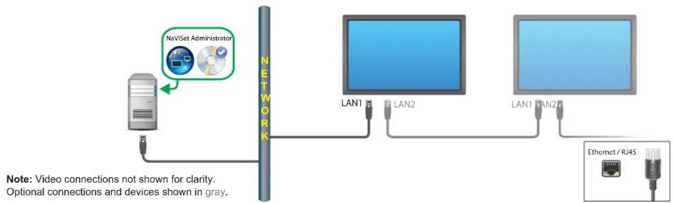
Restrictions
Each display must have a unique IP address.
Monitor IDs can be the same or unique for each display.
If the Auto ID function is used, Monitor IDs will be assigned automatically starting at ID 1 on the first display. See "Using the Auto ID function with a LAN daisy chain" on page 50 for more information.
Notes
For maximum operation speed, it is highly recommended to treat each display as an individually connected LAN display in NaViSet Administrator, rather than as a daisy chain. See page 33 for more information.
NEC large-screen display(s) using LAN to RS232 Bridge
Supported Display Connection Configurations
| RS-232C IN RS-232C OUT | RS-232C IN and OUT |
| RS-232C IN RS-232C OUT LAN | RS-232C IN, OUT, and LAN |
| RS-232C IN RS-232C OUT LAN | RS-232C (IN) and LAN (daisy chain not supported) |
Configuration Overview
Windows computer with one COM port using the "LAN to RS232 Bridge" utility, and connected to a large-screen display via RS232.
Configuration Features
Uses one COM port on the host computer.
Additional displays can be daisy chained via RS232 (if supported).
- Fast command operation.
Adding device(s) to NaViSet Administrator
Select the device type NEC large-screen display connected to LAN when adding devices. See the restrictions below.
Connection Diagram
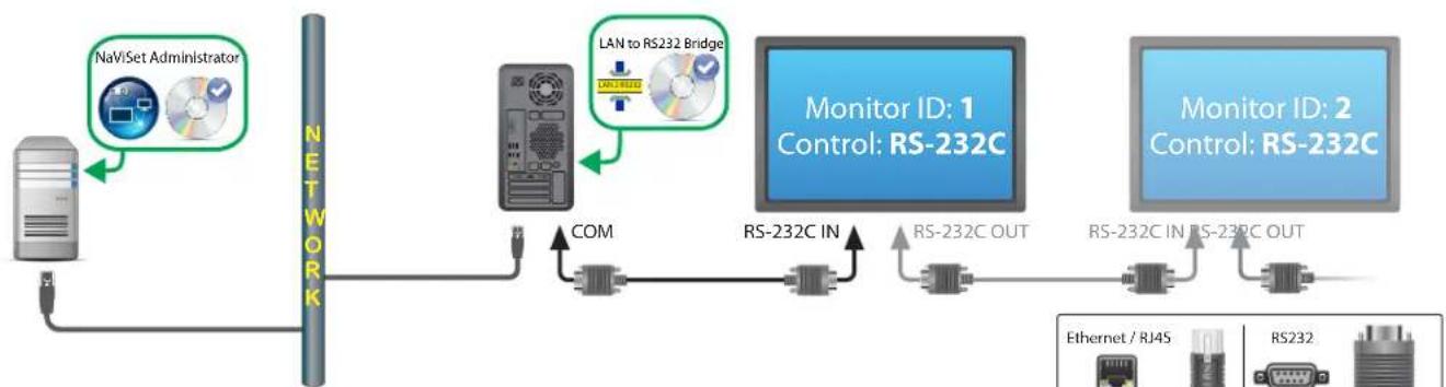
Note: Video connections not shown for clarity. Optional connections and devices shown in gray.
Restrictions
Monitor IDs for daisy chained displays do not have to start at 1, but must be consecutive.
- Displays must be configured to use RS-232C control.
RS-232C cables must be crossover / NULL modem type.
If displays are daisy chained, they must be added to the device tree using Add Single Device... and selecting This is the first display in a daisy chain.
Notes
- Configure the COM port in the "LAN to RS232 Bridge" utility. Select 9600 Baud Rate.
The Windows computer must be running and the user logged-in in order to communicate with displays. - The computer can also be added separately as Windows computer on LAN (WMI) to provide shutdown, restart, Wake-on-LAN, and monitoring of computer parameters.
NEC large-screen display(s) with LAN hub using LAN to RS232 Bridge
Supported Display Connection Configurations

Configuration Overview
Windows computer with one COM port using the "LAN to RS232 Bridge" utility, and connected to a large-screen display via RS232.
Configuration Features
Uses one COM port on the host computer.
Additional displays can be daisy chained via LAN.
- Fast command operation.
Adding device(s) to NaViSet Administrator
Select device type NEC large-screen display connected to LAN when adding devices. See the restrictions below.
Connection Diagram
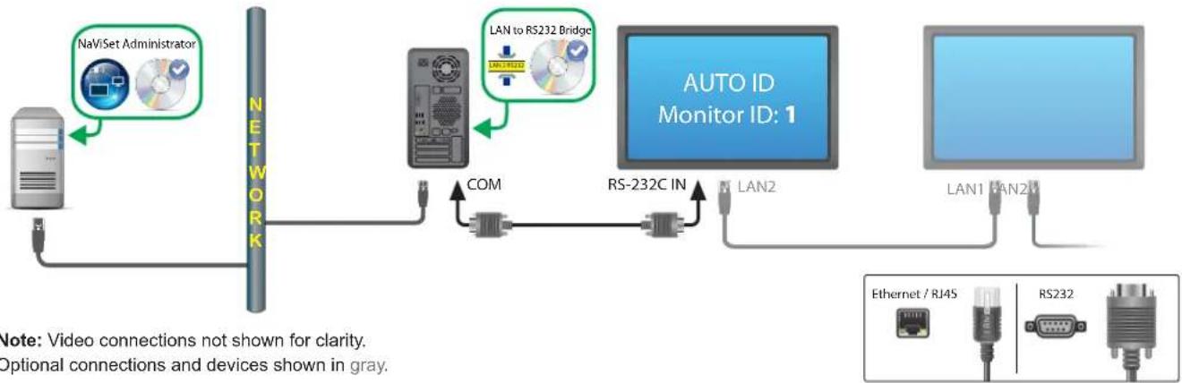
Note: Video connections not shown for clarity. Optional connections and devices shown in gray.
Restrictions
- Auto ID must be performed on the first display via the display's OSD.
RS-232C cable must be crossover / NULL modem type.
If the displays are daisy chained and the IP address settings are set to AUTO, the displays will assign themselves IP addresses automatically. Alternatively, IP addresses can be assigned manually via the OSD.
If displays are daisy chained, they must be added to the device tree using Add Single Device... and selecting This is the first display in a daisy chain.
Notes
- Configure COM port in the "LAN to RS232 Bridge" utility. Select 9600 Baud Rate.
The Windows computer must be running and the user logged-in in order to communicate with displays. - The computer can also be added separately as Windows computer on LAN (WMI) to provide shutdown, restart, Wake-on-LAN, and monitoring of computer parameters.
NEC large-screen display(s) using RS232 WMI Provider
Supported Display Connection Configurations
| RS-232C IN RS-232C OUT | RS-232C IN and OUT |
| RS-232C IN RS-232C OUT LAN | RS-232C (IN), OUT, and LAN |
| RS-232C IN RS-232C OUT LAN | RS-232C (IN) and LAN (daisy chain not supported) |
Configuration Overview
Windows computer with one or more COM ports using "RS232 WMI Provider". Connected to one or more NEC large-screen displays via RS232.
Configuration Features
Supports multiple COM ports on the host computer.
- Displays can be daisy chained via RS232 (if supported).
Supports WMI scripting.
Adding device(s) to NaViSet Administrator
Select device type Windows Computer on LAN (WMI) when adding devices.
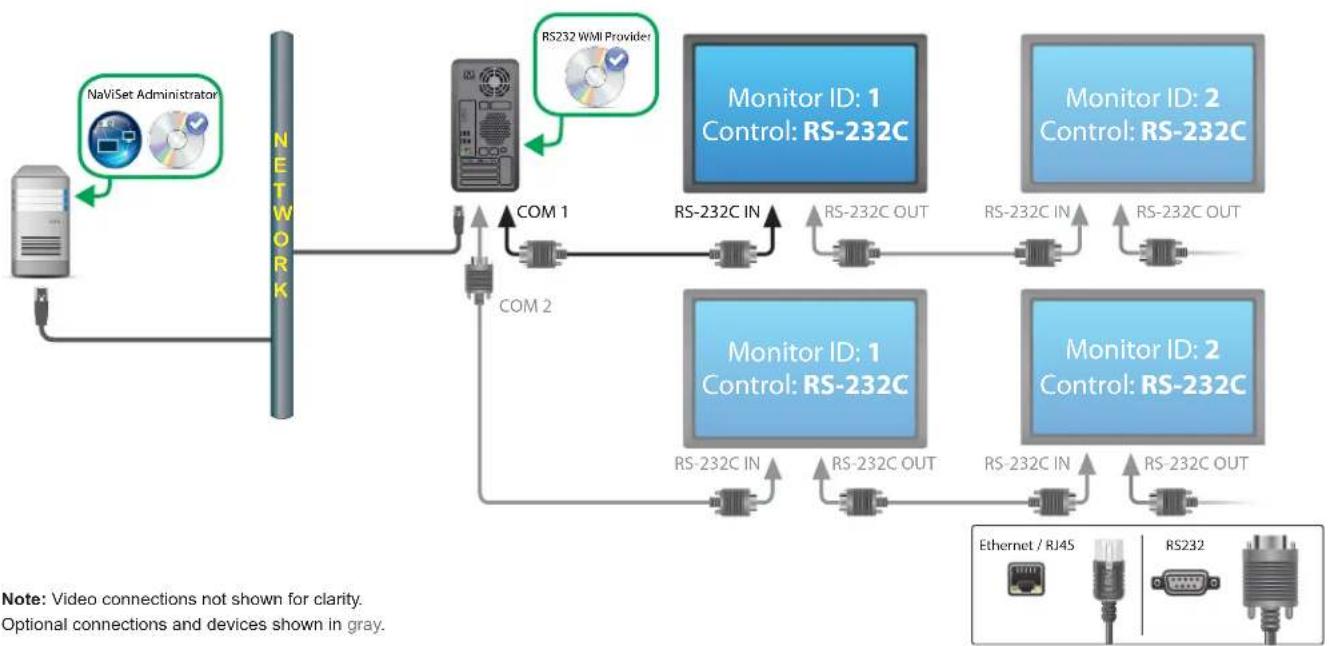
Connection Diagram
Restrictions
- Accessible from the Windows version of NaViSet Administrator only.
Each display on each daisy chain must have a unique Monitor ID. - Configure COM ports and Monitor IDs in the "RS232 WMI Provider" configuration utility. See Appendix E on page 151.
RS-232C cables must be crossover / NULL modem type. - See "Windows Computer on LAN connections via WMI" on page 46 for important information about configuring WMI.
Notes
Monitor IDs do not have to start at 1.
Security is provided by WMI access restrictions.
The Windows computer must be running in order to communicate with the displays.
- For fastest performance use the "LAN to RS232 Bridge" or direct LAN connection.
See Appendix A on page 143 for comparisons between the LAN to RS232 Bridge and RS232 WMI Provider.
- The RS232 Provider cannot be installed at the same time as the DDC/CI WMI Provider.
NEC large-screen display(s) with SBC and dual LAN connections
Supported Display Connection Configurations
| RS-232C IN OUT LAN | RS-232C IN, OUT, and LAN |
| RS-232C OUT LAN | RS-232C (IN) and LAN (daisy chain not supported) |
Configuration Overview
Large-screen display with SBC (Single Board Computer) connected to the LAN. The large-screen display is also connected to the LAN directly.
Configuration Features
- Displays can be controlled even if the SBC is shut down or non-functional.
- Displays can be daisy chained (if supported).
The SBC can run operating systems other than Windows.
Adding device(s) to NaViSet Administrator
Select device type NEC large-screen display connected to LAN when adding devices. See the restrictions below.
Connection Diagram
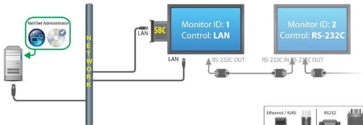
Note: Video connections not shown for clarity. Optional connections and devices shown in gray.
Restrictions
- SBC is accessible from Windows version of NaViSet Administrator only.
Each display on the daisy chain must have a unique Monitor ID, and Monitor IDs must be consecutive.
The first display must be configured to use LAN. Others must be configured to use RS-232C control.
RS-232C cables must be crossover / NULL modem type.
If displays are daisy chained, they must be added to the device tree using Add Single Device... and selecting This is the first display in a daisy chain.
Notes
Monitor IDs do not have to start at 1.
- Two IP addresses are required (one for the SBC, and one for the display).
- The SBC can be added separately to the device tree as Windows computer on LAN (WMI) to provide shutdown, restart, Wake-on-LAN, and monitoring of computer parameters.
NEC large-screen display with SBC and single LAN connection
Supported Display Connection Configurations
| RS-232C IN OUT | RS-232C IN and OUT |
| RS-232C IN OUT LAN | RS-232C IN, OUT, and LAN |
| LAN1LAN2 RS-232C | RS-232C (IN), LAN1, and LAN2 |
| RS-232C LAN | RS-232C (IN) and LAN |
Configuration Overview
Large-screen display with SBC (Single Board Computer) connected to LAN, also using the internal RS-232C connection to the SBC for communications.
Configuration Features
- Single LAN connection using one IP address.
Can use either the "LAN to RS232 Bridge" or "RS232 WMI Provider".
Adding device(s) to NaViSet Administrator
When adding devices, select device type:
NEC large-screen display connected to LAN if using the LAN to RS232 Bridge.
or
Windows Computer on LAN (WMI) if using the RS232 WMI Provider.
Connection Diagram
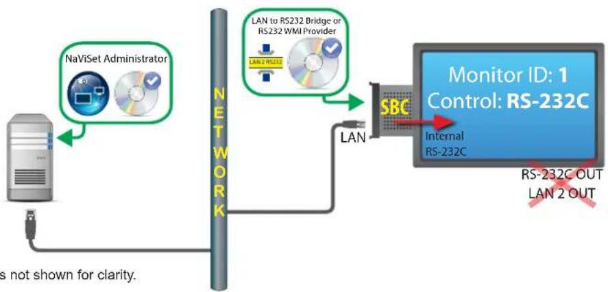
Note: Video connections not shown for clarity.
Restrictions
- WMI connections are accessible from Windows version only.
- The "LAN to RS232 Bridge" or "RS232 WMI Provider" must be used.
Additional displays cannot be daisy chained from the RS232 OUT or LAN 2 (output) when using the SBC's internal RS-232C connection. - The display must be configured to use RS-232C control unless the display model supports LAN based daisy chains (Models supporting LAN based daisy chains have RS-232C IN, LAN1 and LAN2 connectors).
- Do not use the "DDC/CI WMI Provider" with an SBC. The internal connection to the display supports RS232 communications only.
If using the RS232 WMI Provider, see "Windows Computer on LAN connections via WMI" on page 46 for important information about configuring WMI.
Notes
Monitor ID does not have to be 1.
One IP address is required.
The SBC must be running Windows and be operational in order to communicate with the display(s).
See Appendix A on page 143 for comparisons between the LAN to RS232 Bridge and RS232 WMI Provider.
NEC projector using direct LAN connection
Configuration Overview
NEC projector connected directly to a wired or wireless LAN.
Configuration Features
- Single LAN connection using one IP address.
- Operates without a computer.
Adding device(s) to NaViSet Administrator
Select device type NEC projector connected to LAN when adding devices.
Connection Diagram
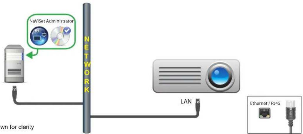
Note: Video connections not shown for clarity
Notes
- Some projector models require the communications setting to be manually configured between RS232 and LAN via the On Screen Display. Select LAN for this configuration.
NEC projector connected via Windows Computer to LAN
Configuration Overview
NEC projector connected to a Windows computer via RS-232C, and the computer is running the "LAN to RS232 Bridge" utility.
Configuration Features
- Shared LAN connection using one IP address.
Supports projector models without LAN interface.
Adding device(s) to NaViSet Administrator
Select device type NEC projector connected to LAN when adding devices.
Connection Diagram
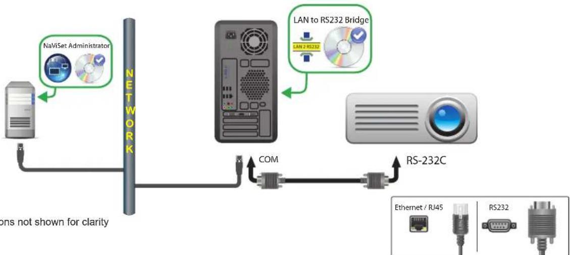
Note: Video connections not shown for clarity
Restrictions
- Configure the Baud rate in the LAN to RS232 Bridge utility to match that of the projector. Available rates are 9600, 19200, and 38400 baud.
- Some projector models require the communications setting to be manually configured between RS232 and LAN via the On Screen Display. Select RS232 for this configuration.
- Configure the RS232 COM Port in the LAN to RS232 Bridge utility to the COM port used on the computer.
- Computers running the LAN to RS232 Bridge utility are not able to provide network enumeration of the connected projector. The projector cannot be automatically identified on the network using the projector Enumerate function in NaViSet Administrator. The IP address or hostname of each computer must be manually entered instead.
RS-232C cable must be crossover / NULL modem type.
Notes
- The Windows computer can also be added separately as Windows computer on LAN (WMI) to provide shutdown, restart, Wake-on-LAN, and monitoring of computer parameters. WMI connections are accessible from Windows version only.
The computer must be running and the user logged-in in order to communicate with the projector.
PJLink compatible device using direct LAN connection
Configuration Overview
PJLink compatible device connected directly to a wired or wireless LAN.

Note: Refer to the device's user guide for instructions on how to configure the network connection and enable the PJLink functionality.
Configuration Features
- Single LAN connection using one IP address.
- Operates without a computer.
Adding device(s) to NaViSet Administrator
Select device type PJLink device connected to LAN when adding devices.
Connection Diagram
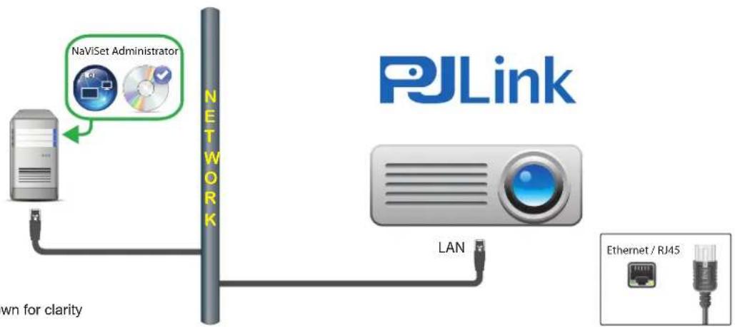
Note: Video connections not shown for clarity
Available Functions
Depending on the features of the connected device, NaViSet Administrator can access the following:
Device information (Manufacturer, Model, Device name)
- Change the power state
Change the video input signal
View the lamp usage
View diagnostic information (e.g. error status)
Mute or unmute the audio and video
Network password
Restrictions
The device serial number cannot be read via PJLink.
This connection type is not intended for use with NEC devices. Please refer to the previous sections for instructions on connecting to NEC display devices.
Chapter
5
Controlling Devices
Devices can be controlled either interactively on an individual basis using the controls in the Device Properties Windows, or in groups as part of a Task operation (see "Tasks" on page 81).
To control a device interactively, double-click the device icon in the device tree to open the Device Properties Window, which will contain one or more tabs with information and controls relating to the device.

Read-only displays (Windows version only)
Read-only displays, where two-way communications with the display is not available or supported, only have an Info tab, and no interactive controls are available. The information shown from the display is read-only and static, such as serial number, model name, and date of manufacture.
A display may be read-only for one or more of the following reasons:
- The DDC/CI WMI Provider has not been installed on the remote Windows computer.
- The DDC/CI WMI Provider has been installed on the remote Windows computer; but the video graphics chipset may not support DCC/CI communications with the display.
The input being used on the display may not support DDC/CI (for example, HDMI inputs do not support it).
The display is not a supported model or is not an NEC model.
Interactive Control
For devices that are not read-only, several tabs grouped into different types of controls will be shown. Controls can be adjusted in real-time and the remote device will be updated automatically.
The available controls will depend on the type of device and the connection to the device. NaViSet Administrator will automatically query the device to determine the capabilities and controls available.

Note: Changes to the settings and controls on a display cannot be made when the device is in the Power Off state. It must first be powered on before making any setting or control adjustments.
As different tabs are selected, the remote device will be queried to read the latest settings for the controls displayed on the tab. This can take a few seconds to complete. The settings can also be read from the display and updated by clicking the Refresh button on a tab.
The following table shows the different types of tabs that can be shown depending on the capabilities of the device selected.
| Tab Descrip t i o n | |
| Info | A summary of the most common device properties. If a Full Refresh has been performed on the device, all of the supported control settings from the device will be shown. |
| Network | Network settings used to connect to the device such as IP address and credentials. |
| Power | Power On and Off, and other power related controls. Windows computers include controls for Shutdown, Restart, and System Wake-on-LAN.1 |
| Video | Controls for adjusting the video settings such as video input, brightness, color, etc. |
| Geometry | Controls for adjusting the positioning and scaling of the video signal on the screen. |
| Audio | Audio related controls such as volume. |
| Display Schedule | Controls for configuring the internal scheduling function (schedules that run autonomously within the display) in supported large-screen displays. |
| POP | Shows all of the Proof of Play events for this device. Controls are also provided for enabling/disabling Proof of Play for this device and start/stopping the Proof of Play task. |
| OSD | Controls for configuring settings relating to the On Screen Display |
| IR Remote | Used to send commands equivalent to pressing the buttons on the device's IR Remote controller. Available on large-screen displays and projectors. |
| ECO | Controls relating to ECO and power saving. |
| Custom | Shows a list of all controls available on the device that can be selected and adjusted. This includes more infrequently used controls not shown on other tabs. |
1 Accessible from Windows version only
Info Property Tab
The Info device property tab shows a summary of the essential information about a device, such as the model name, serial number, IP and MAC addresses, and many others depending on the device type.
When a device is first added to the Device Tree, the basic information about the device is read and stored in the database.
Information about a device can be refreshed at any time using either the Standard Refresh or Full Refresh functions (see "Standard Refresh vs. Full Refresh" on page 71 for more details), which are available both on the Info device property tab, and from the device tree's context menu, shown by right-clicking on the device.
The date and time the information was last updated is shown in Last Refresh: This text will be shown in red if the device had not been refreshed within the last 24 hours.
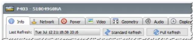
The information shown on the Info tab can be exported to the clipboard, an Excel spreadsheet, or a delimited text file by clicking the Export... button. Also, information from individual tables can be copied to the clipboard by first selecting the desired rows in the table, then selecting Copy from the Edit menu, or by pressing Ctrl+C.
Windows Computer Info
The Info property tab for remote Windows computer devices shows information about the computer such as the operating system, service pack, CPU type, total and available RAM, and if supported by the hardware, the make, model, and serial number of the computer.
The OS version, service pack and architecture are also shown, along with the CPU type, speed, and current usage percentage. The installed physical memory size and currently available memory is shown.
If Open Hardware Monitor (see Appendix C on page 146) is installed on the remote computer, the CPU, GPU, and Main Board temperatures and fan speeds will be reported if supported.
Projector or Large-screen Display Info
The Info tab includes information such as the model name, serial number, IP and MAC address of the display.
If the display supports Diagnostics reporting, or includes internal temperature sensors, these readings will be shown.
The Power On Time counter value will be shown in both hours and days if supported by the display.
Projectors that support reading the number of hours used and hours remaining on lamps and filters will show this information also.
Desktop Display Info
For a desktop display device, the Info tab includes information about the related video graphics system on the computer for the display, such as the display adapter model, driver version, and current video resolution settings.
If the display supports Diagnostics reporting, or includes internal temperature sensors, these readings will be shown.
The Power On Time counter value will be shown in both hours and days if supported by the display.
PJLink Device Info
The Info tab includes information such as the model name, manufacturer, IP and MAC address of the device.
Standard Refresh vs. Full Refresh
Standard Refresh will read and update the basic information about a device.
For display devices, this includes items such as:
Model Name
Serial Number
Date of Manufacture
- Diagnostics
Asset Tag
For desktop displays connected to a Windows computer and accessed via WMI, additional information about the computer and video graphics system, such as the display adapter manufacturer, model, driver version, and many more items will be shown.
Full Refresh will perform a Standard Refresh plus read and update information about all of the supported controls and their current setting values. All of the settings read will be listed in the tables on the Info tab. Because of the large number of controls supported on many devices, the Full Refresh can take over a minute depending on the device and connection type.
Note:
Performing a Standard or Full Refresh will overwrite all of the device information saved in the database from the last Standard or Full Refresh.
Information for devices that are currently powered off cannot be fully updated until they are fully powered on and available for remote access.
- When a Standard or Full Refresh is performed directly on a Windows computer, any new display devices will be automatically detected and added to the device tree. If an existing device has been disconnected or can no longer be accessed, an option to delete the device will be given.
Grouped Controls Tabs
Several controls are grouped in a series of tabs for quick access. When a tab is first opened, the device is queried and the controls are refreshed with the current settings.

Note: The controls displayed in the Group Controls tabs is only a subset of the most common controls. The Custom tab, described on page 76 provides the complete list of controls available for the device.
Controls can exist in 4 different operational states, as follows:
| Control State Description Example | ||
| Normal, Read/Write Fully interactive, synchronized to the current setting of the device. | Brightness (%) 55 Max | |
| Read-only (blue border) A device setting or reading that cannot be adjusted. | Illuminance Reading (lux) 230 Dark Bright | |
| Control State Description Example | ||
| Execute-only An operation | based control. Most of these types of controls consist of a single push button. | Reset Video Reset |
| Unavailable (red border) A | control that typically is supported by the device but could not be accessed at the time the tab was either opened or refreshed. | Red Gain: unavailable Min Max |
Controls Context Menu
A context menu can be opened by right-clicking on the control.
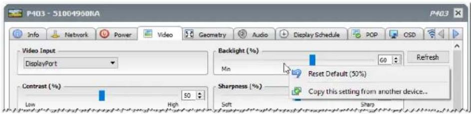
The context menu provides these actions:
Reset Default - Changes the setting back to the device's default value. This function is available only for slider-based controls.
Copy this setting from another device... - Allows for the selection of another device from which to copy the current setting. Once a device is selected it is immediately queried for the setting, which is then applied to the control. The devices selected will be added to the controls context menu to facilitate follow-up copy operations and will remain until the application is closed.
Display Schedule Property Tab
This tab is shown when controlling an NEC large-screen display that supports internal schedules (schedules that run autonomously within the display).
Multiple schedules can be configured for setting the display to power on and off at specific times and days, as well as changing to different video inputs and picture modes. The number of supported internal schedules that can be configured depends on the model of the display being used. Once configured in the display, it will perform the programmed schedule using the internal clock and a connection to NaViSet Administrator will not be needed.
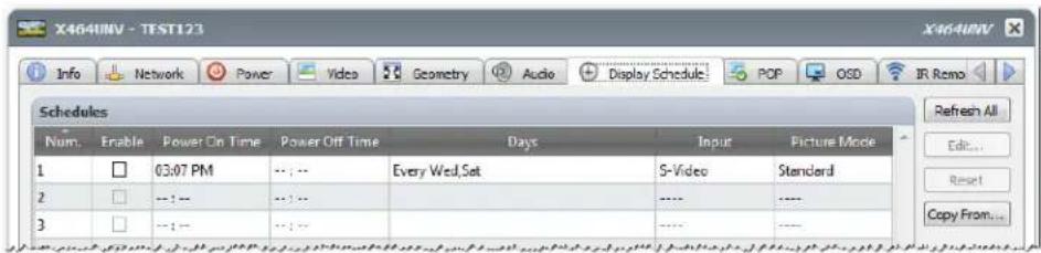
To create or edit a schedule, select one of the schedule lines and click the Edit... button to open the Edit Schedule dialog. Select the scheduling options and then click on Save.
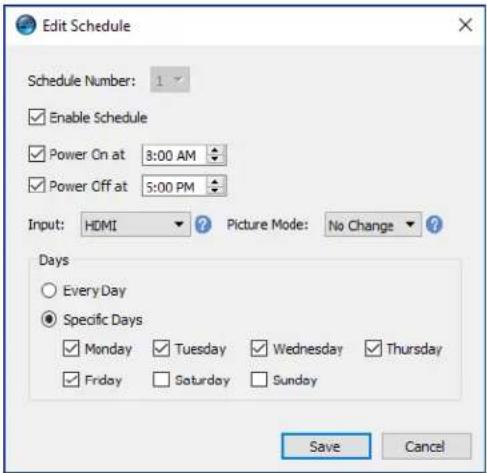

Note: Depending on the display model, the Edit Schedule dialog may have additional selection options for Dates, Weekdays, Weekends, and Holidays. The days for the weekends and holidays must be defined in their applicable dialogs before by selecting them in the Edit Schedule window. Please see "Holiday and Weekend Schedules" on page 75.
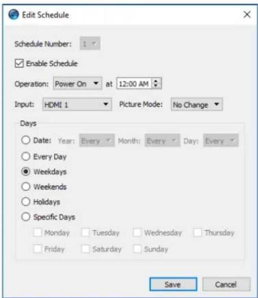
Select one of the schedules and click the Reset... button to clear the schedule from the display.
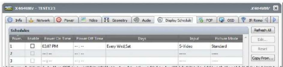
To copy existing schedules from a different display, click the Copy From... button to open the Device Selector dialog. Select the display to copy the settings from and then click on OK.
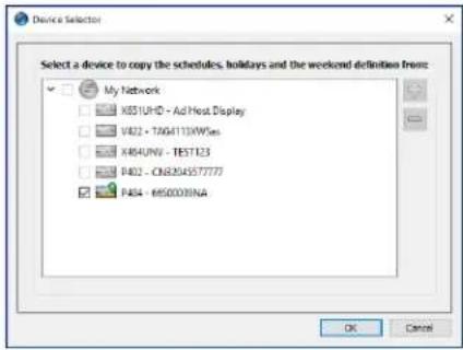
Note: Copying schedules between different display models may not be available as not all displays have the same scheduling options.
Next, a dialog opens showing the list of schedules that are in the selected display. Click on OK to copy the schedules.
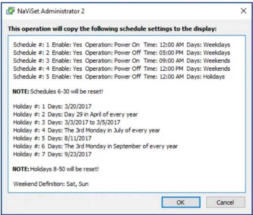
Important: This action cannot be undone. All scheduling information in the display will be replaced with the settings copied from the selected display. This includes holiday and weekend definitions for displays that support them. Please see "Holiday and Weekend Schedules" below.
Holiday and Weekend Schedules
Depending on the display model, additional options may be available in the Display Schedule tab for defining holidays and weekends. Click the Holidays... or Weekends... button to set the holiday dates and weekend days for where the displays are located.
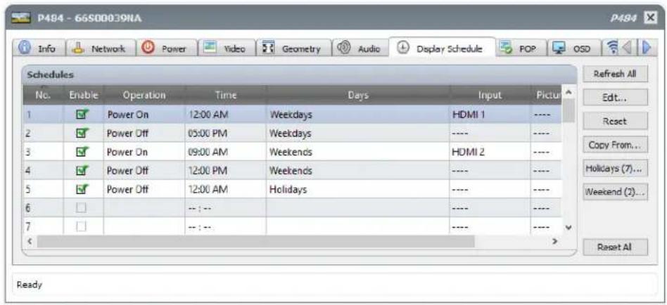
Holidays
To set the holiday dates, click on the Holidays... button to open the Holidays dialog.
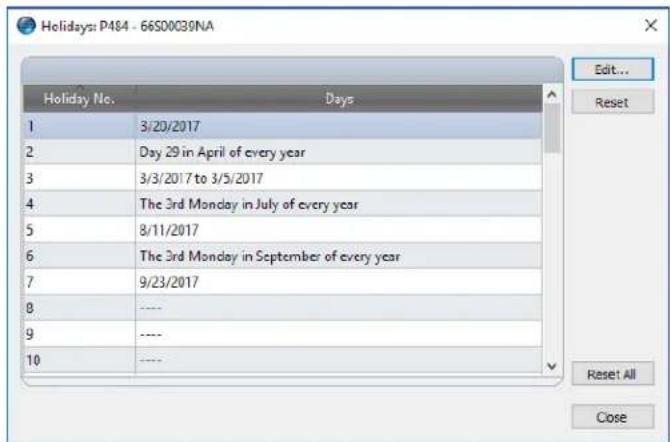
Click Edit... to open the Edit Holiday dialog to set which dates are to be considered holidays.
Select an existing holiday and click Edit... to change the dates for an existing holiday.
Select an existing holiday and click Reset to remove the holiday from the list.
Click Reset All to clear all holidays from the list.
In the Edit Holiday dialog, select the options to define what the holiday days are going to be and then click on Save. For example, to create January 1st as a holiday leave the "Year" field blank, select Jan from the "Month" menu, and select 1 in the "Day" menu. The description for the holiday will update to show what has been selected in the dialog, such as "The 1st day in January of every year".
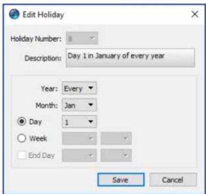
Weekends
To set which days of the week are to be considered weekend days, click on the Weekends... button to open the Weekend Definition dialog.


Custom Property Tab
The Custom device property tab lists all of the controls available on the device that can be adjusted. The list includes more infrequently used controls not shown on other tabs.
To adjust a control, select it from the Controls list and it will be added to the Settings list shown on the right side. The remote device will be queried in real-time to read the current setting for the selected control. If an adjustment or change is made to a control the new setting will be sent to the remote device and confirmed. This process can take a few seconds to complete.
Multiple controls can be added to the Settings list and the order of the list can be changed using the and buttons. Settings can be removed from the list by clicking the button.
The Settings list for a device can be saved by clicking the Save List button, and the controls shown in the list will be restored the next time the device's Properties Window is opened.
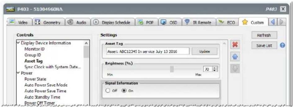

Note: The controls context menu described on page 72 is also available for the controls in the Custom tab.
Some of the more unique controls available on the Custom Controls list are shown below.
Asset Tag
For NEC devices, a custom text string can be entered and stored in the display. This text string could, for example, be a conventional asset tracking code, company name, department name, phone number, etc. This can then be read by NaViSet Administrator and used for asset tracking over a network. For desktop displays and large-screen displays, this text can normally only be altered or erased by using NaViSet Administrator. On projectors the Asset Tag is known as the Projector Name.
Only ASCII based characters can be entered and the length is limited by the capabilities of the device.

Sync Clock with System Date/Time
For large-screen displays that have an internal clock for performing schedule functions automatically, the clock can be synchronized with the time and date from the local computer. If the display is located in another time zone, the time applied to the display can include an offset value of from -23 to +23 hours relative to the local time. For example, to correctly set the clock for a display physically located in a time zone 2 hours ahead of the local time, select an offset of +2 hours, and click Update.
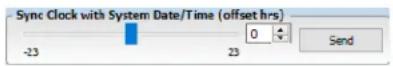
TV Channel
For large-screen displays that have an internal TV tuner, the TV channel can be set using the TV Channel Control. Enter the channel and sub-channel numbers and then click Update to change. The TV tuner must be selected as the current video input.

Chapter
6
Credential Library
About the Credential Library
NaViSet Administrator has a Credential Library feature for managing credentials and making it easier to store and apply credentials for accessing multiple computers or PJ Link devices. This saves having to enter the same credentials again each time a new device is added. The passwords entered are encrypted and stored in the current database file.
Using the Credential Library
The Credential Library can be accessed from:
The Devices menu.
The Credential Library button on the toolbar.
The Network tab of a Windows computer or PJLink device.
- When using Add Single Device with a Windows Computer on LAN (WMI) or PJLink Device.
- When using Add Multiple Devices with Windows Computers (WMI) or PJLink Devices.
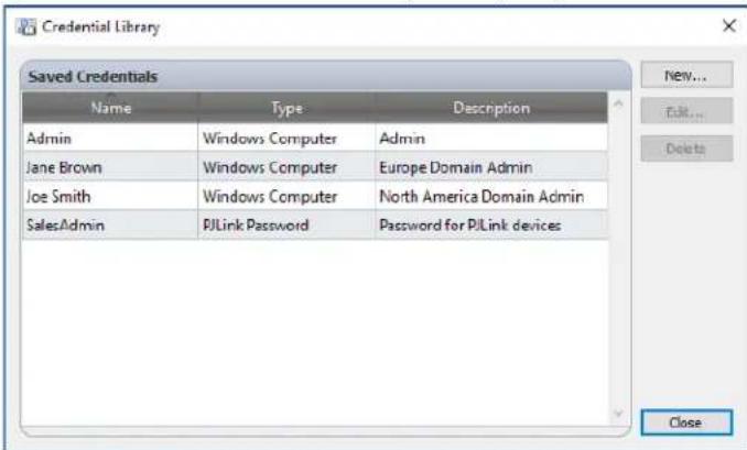
Credentials for Windows computer on LAN (Windows version only)
Access credentials must be specified when connecting to remote Windows computers via WMI. These credentials must be for a user with sufficient access permissions for administering the computer and accessing WMI. The credentials consist of a User name and Password.

Note: If the user is a member of a different domain than that of the computer, then the user name can be specified in the format domain\username.

Note: Credentials are not used for local connections (connections to the same computer that is running the NaViSet Administrator application). Credentials can be entered for a local connection, however, since they aren't used, the local connections should not be used to verify administrator credentials.
Adding a new credential
Click the New... button in the Credential Library to open the New Credential dialog. Select the Windows Computer credential type. Input the User name (with optional domain specifier), Password, and a Name alias, and optionally provide a description to be shown in the Credential Library list.
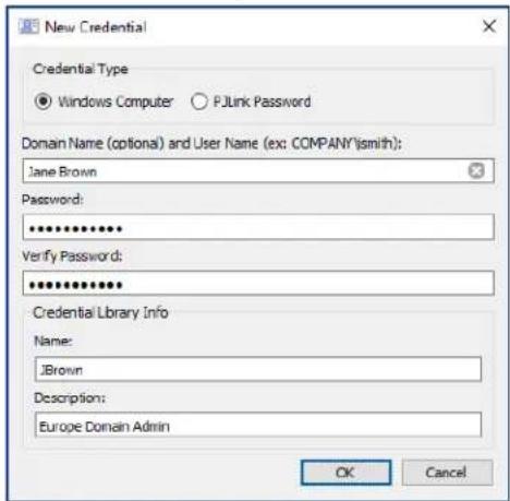
Editing an existing credential
Click the Edit... button in the Credential Library to open the Edit Credential dialog. Changes to credentials will automatically be applied to all device connections using the credential.
Deleting an existing credential
Click the Delete button in the Credential Library to delete a credential from the library.
Credentials for PJLink Devices
Adding a new credential
Click the New... button in the Credential Library to open the New Credential dialog. Select the PJLink Password credential type. Input the Password and a Name alias, and optionally provide a description to be shown in the Credential Library list.
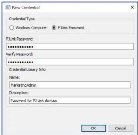
Editing an existing credential
Click the Edit... button in the Credential Library to open the Edit Credential dialog. Changes to credentials will automatically be applied to all device connections using the credential.
Deleting an existing credential
Click the Delete button in the Credential Library to delete a credential from the library.
Chapter

Tasks
About Tasks
Tasks are operations that query or perform commands on one or more devices. Tasks can be scheduled to start at particular times or on demand. Tasks can be configured to run once or continue running for a specific period of time and at specified intervals.
There are 4 basic types of task that can be performed in NaViSet Administrator:
Command Tasks: Change settings or perform operations on devices. For example, turning the display power on, selecting a particular video input, or selecting a particular channel on the TV tuner. Command Tasks can also be used to create a preset configuration of multiple settings that can be then sent to displays to perform easy configuration.
- Conditional Tasks: Read one or more settings or parameters from devices at periodic intervals, and issue alerts and/or send commands to the display if any of the values are outside of a specified range or value, or changes in value. For example, an alert can be issued if the internal temperature of a display exceeds a specific value, or if a diagnostic error condition is reported by a display.
- Informational Tasks: Read one or more settings or parameters from devices at periodic intervals, and displays the readings in real time. An example use would be to continuously monitor the internal temperature of a display.
- Built-in Tasks: Special tasks created by the system. These tasks will be visible only if devices that support them exist in the device tree. An example of a built-in task is Proof of Play, described at the end of this chapter.
When a Task is run it will attempt to perform the specified operation on each of the devices selected in the Task before completing. For Conditional and Informational type tasks, the task can be set to poll the devices at specific intervals, either indefinitely, or for a specific run time.
The status of running tasks can be monitored in real-time. Upon completion, the result history of every operation is saved in the database for use at a later time. Task history can also be exported to an Excel spreadsheet or delimited text file, or copied to the clipboard.

Task Library
All tasks are managed using the Task Library, available on the Tasks menu or by clicking the toolbar button. Tasks can be created, edited, duplicated, and deleted from within the Task Library. The execution history of a task can also be viewed and exported.
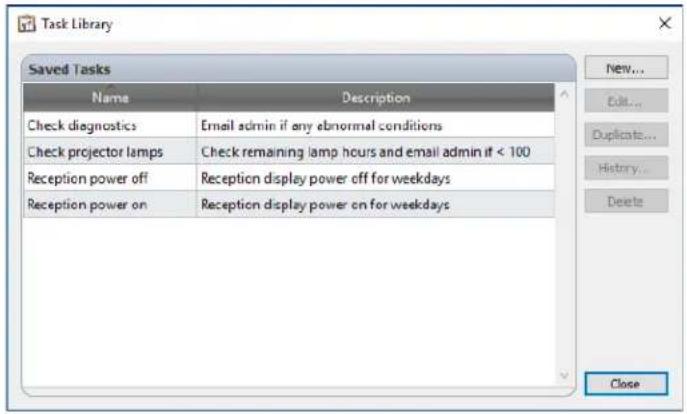

Task Manager
All Tasks in the current database are listed in the Task Manager window.
This window shows:
- Tasks that are currently inactive (not currently being processed/executed)
- Tasks that are currently active (being processed/executed)
Any alert conditions that have occurred while running any tasks
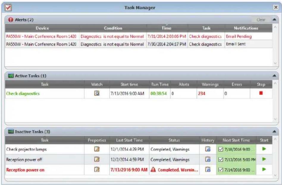
Inactive Tasks list
Inactive Tasks are tasks that are either scheduled to run and are waiting for their start time to occur, or tasks waiting to be started manually. For Tasks that are scheduled to run, the Next Start Time is shown with a green background. The checkbox in the Next Start Time column can be used to temporarily disable the automatic starting of a task with the schedule. Any task can be made to start immediately by clicking the Start button.
Note: A task will not start if its task properties dialog is opened at the same time that it is scheduled to start. Instead, it will be rescheduled for the next start time when the dialog is closed.
The properties of a Task can be edited by clicking on the Properties button. This is the same as editing a task from the Task Library.
The history of a task can be viewed by clicking the task History button in an inactive task. This is the same as viewing the history from the Task Library. The task history lists the results from each time the task was executed.
For tasks that have executed during the current session, the Status column will include an icon next to the description indicating the overall result status. The text color of the task row will also be changed and made bold. The icons and colors used are as follows:
The task completed or was canceled without alerts, warnings or errors. Text will change to green.
A lower level warning, such as a control that is not supported by the device. Text will change to brown.
The task completed with at least one alert. This icon overrides any additional warnings or errors. Text will change to red.
At least one error or one high level warning, such as a device connection failure. Text will change to red.
A context menu providing quick access to common task operations can be opened by right-clicking on the task. The context menu provides these actions:
Library - Opens the Task Library with the task selected.
Properties - Opens the Task Properties dialog for review or editing.
Schedule - Opens the Task Properties dialog with the Run Schedule tab selected.
History - Opens the Task History Viewer.
Start - Starts the task.
Clear History - Permanently deletes all task history information.
× Delete-Deletesthe task.
Active Task list
The Active Task list shows Tasks that are currently being processed. Tasks that are configured with a schedule to start automatically, will move from the Inactive Task list to the Active Task list while they are being processed. Once the task has been completed, or is manually stopped, it will return to the Inactive Task list again until the next scheduled start time is reached, or it manually started.
While a task is active, the progress of the task can be viewed in real-time by clicking the Watch button. An active task can also be manually stopped by clicking the Stop button.
The number of alerts, warnings or errors that occur while a task is running are shown.
Alerts list
Alerts occur when a condition in a conditional type task becomes true. Alerts issued by a task are listed in the Alert list. The Alerts list shows the task and condition that caused the Alert, the device it occurred on, the time it occurred, and any notifications that were sent.
The Alert list contents can be permanently cleared by clicking the Clear button.
- Individual alerts can be deleted by right-clicking on the alert and selecting × Delete.
- The Device Properties window can be opened directly from the Alerts table by right-clicking on the alert and clicking the Device Properties button.
- Alerts messages generated during the current application session are shown with red text, and alerts created in previous sessions are shown with normal text.
- More detailed information about a device or a notification can be seen by mousing over the device or notification columns respectively.
- Clicking on a row in the Alerts list will automatically select the corresponding device in the Device Tree.
- Double-clicking a row while the task is running will open the Task Viewer window and select the row containing the alert. Similarly, if the task is no longer running the Task History window will be opened.
When an alert is issued, the Alert notification button is shown at the bottom right side of the main application window. Mouse-over the button to view details about the last alert condition. Clicking this button will open the Task Viewer dialog and select the alert.
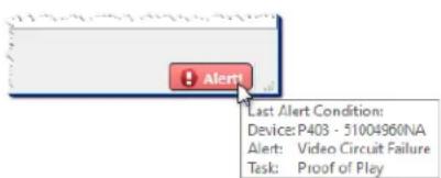
If enabled in the application Preferences (see page 116), an Alert will also be shown in a popup message in the Windows Task Tray (Windows version), or the Status Menu (macOS version):
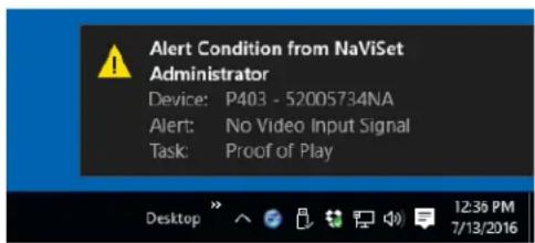
Creating Tasks
Tasks can be created using a step-by-step wizard interface in the Task Builder Wizard, available on the Tasks menu, or by clicking the Task Builder Wizard button. The wizard offers a guided explanation of each step of creating a task.
Tasks can also be created directly by selecting New Task... on the Tasks menu, or clicking the New Task button, or by selecting New... from the Task Library.

Note: The IR Remote and Display Schedule functions are not available when using the Task Builder Wizard. To use these functions, create a new task without using the Task Builder Wizard.
Creating a New Command Task
Command type tasks perform actions on devices such as changing control settings or performing operations.
Create a new task by selecting New Task... from the Tasks menu, or selecting New... from the Tasks Library, or click the New Task button on the application toolbar.
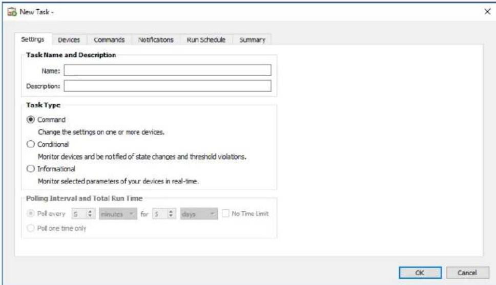
Settings Tab
First, give the task a name and description so it can be easily identified in the task list.
Next, select Command as the type of task to be created.

Note: Command type tasks are only performed one time each time the task run, so the Polling Interval and Total Run Time section is disabled.
Devices Tab
Next, select the Devices tab and select at least one device that the task will be performed on. Selecting a group will automatically select all of the devices within that group.
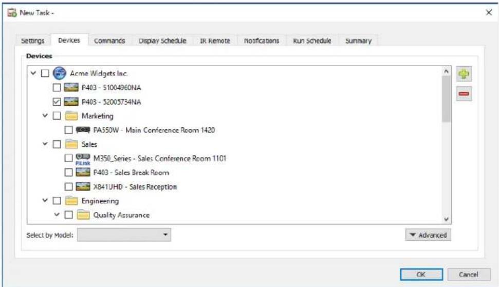
Devices can also be selected by model using the Select by Model listbox. Selecting a model in the list will select all matching devices in the device tree. The + button will select all devices, and the - button will clear all selected devices. Clicking the Advanced button shows additional settings for handling devices in the task.
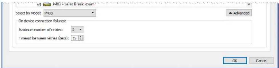
Maximum number of retries - Select the number of times running tasks and reports should attempt to connect to devices.
- Timeout between retries - Enter the number of seconds to wait between each retry.
Commands Tab
Next, select the Commands tab and select a control to be changed or adjusted from the control list. Once the control has been added to the list of commands, the parameters or settings for the control can be set.
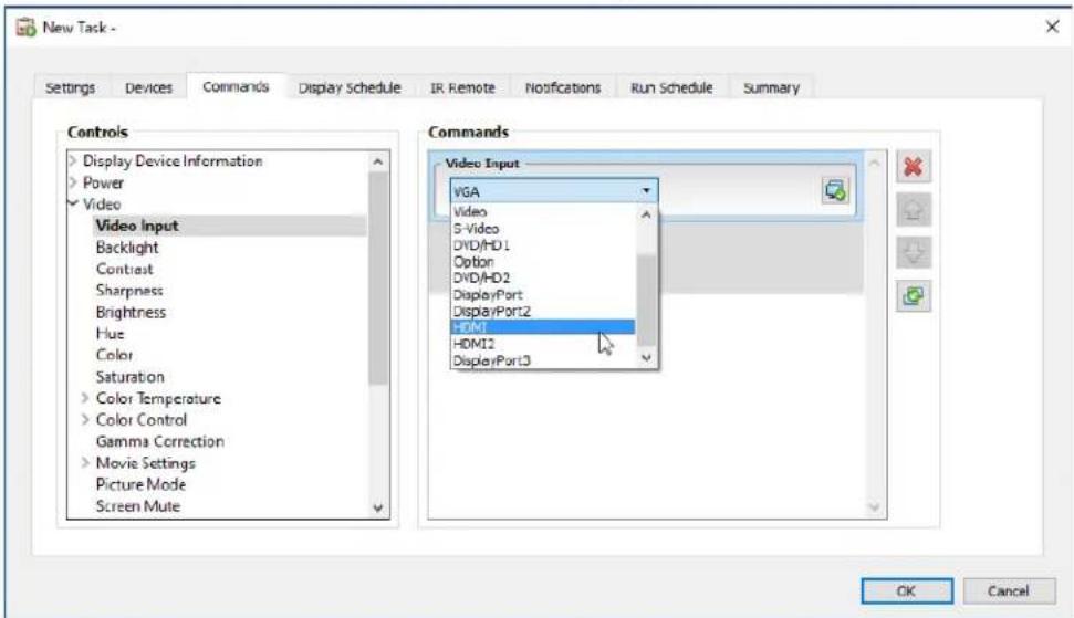
Continue adding other controls to the command list as necessary. By default, each command will be applied to all of the devices selected in the Devices tab. However, once a control is added a subset of the devices can be selected using the button.
Clicking the button for a command opens the Device Selector dialog, from which the devices to perform the command on can be specifically selected.
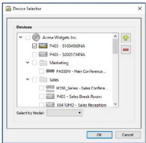
Multiple instances of the same control can be added, each with different devices and settings selected, thus allowing one task to perform different control operations on different devices. See "Example Task: Using Device Specific controls to configure a Tile Matrix" on page 132 for an example of how this functionality can be used.
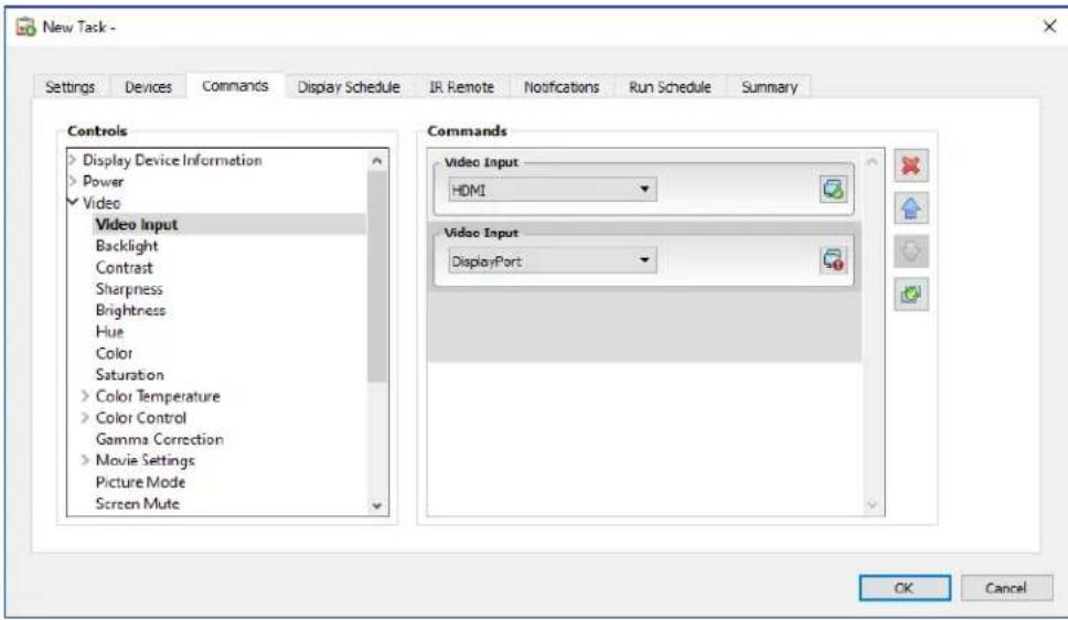
Note:
- The types of controls listed in the Commands tab depends on the types of devices selected.
Not all devices support all of the commands and setting values listed.
The task executes the commands one at a time, and in the order they appear in the list. For some commands the ordering may be important, and can be changed using the and buttons.
Specific vs. Generalized Controls
NaViSet Administrator allows different types of devices and display models to be controlled in a single task. If a group of devices is selected that are not all of the same model then a generalized version of the controls may be automatically selected. A generalized control set is indicated by an alert window shown over the control list.
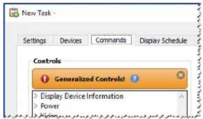
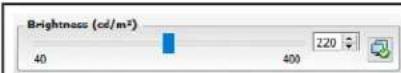
Specific controls show the actual values for a device and the units, which closely resemble the device's OSD and User's Manual.
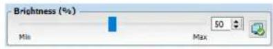
Generalized controls typically use a percentage range from 0 to 100, which are then translated to actual values for each device when the task is run.

Note: Except for basic commands such as Power On/Off and Audio Volume, the use of generalized controls should be avoided. This can be done by creating separate tasks that run on similar models and/or types of devices.
Copying settings from other Devices
The controls in a Command task can easily be adjusted to match the current settings of other devices.
To copy all of a task's control settings from one other device, select the button and choose the device to copy from.
To copy settings from different devices to specific controls, right-click on each control separately, select Copy this setting from another device... from the context menu, then choose the device to copy from.

Note: These operations read the current settings of the "source" device at the time the task is created or edited, and not at the time the task is run. If future adjustments are made, existing tasks can be updated with the new settings by opening the task properties window and repeating the above procedures.
Display Schedule Tab
If one or more of the devices selected is an NEC display that supports internal scheduling (schedules that run autonomously within the display), the Display Schedule tab will be shown.
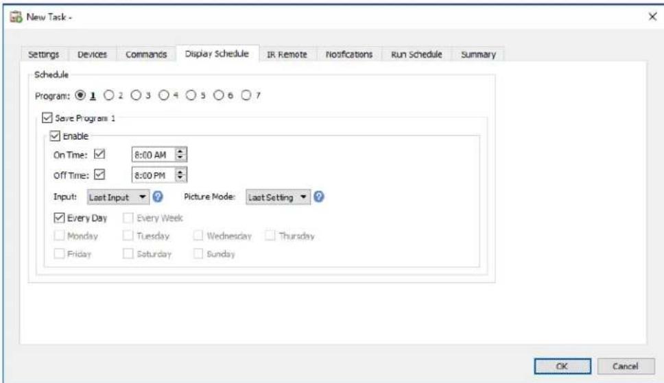
The schedule settings can be optionally set for each of the 7 supported internal schedules to power the display on and off, as well as setting different video inputs at specific times on specific days. When the task is run it will program the selected displays with these schedule parameters. Once the displays have been programmed via the task, it is not necessary to use NaViSet Administrator to perform the same schedule functions since the displays will perform them automatically using the internal clock and scheduling feature.

Note: The display's internal clock can be synchronized to the current date and time by using the command Sync Clock with System Date/Time control listed in the Display Device Information category. This control allows the display's internal clock to be set with an offset value of from -23 to +23 hours, relative to the local time. This is useful if the display being set is located in a different time zone. So, for example, to set the internal clock for a display that is located in a time zone two hours ahead of the current local time, set the Offset hrs value to 2. All displays in this task will be set using the same offset value, so displays across multiple time zones should be split into separate tasks.
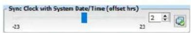
IR Remote Tab
If one or more devices selected supports sending IR remote control commands, the IR Remote tab will be shown.
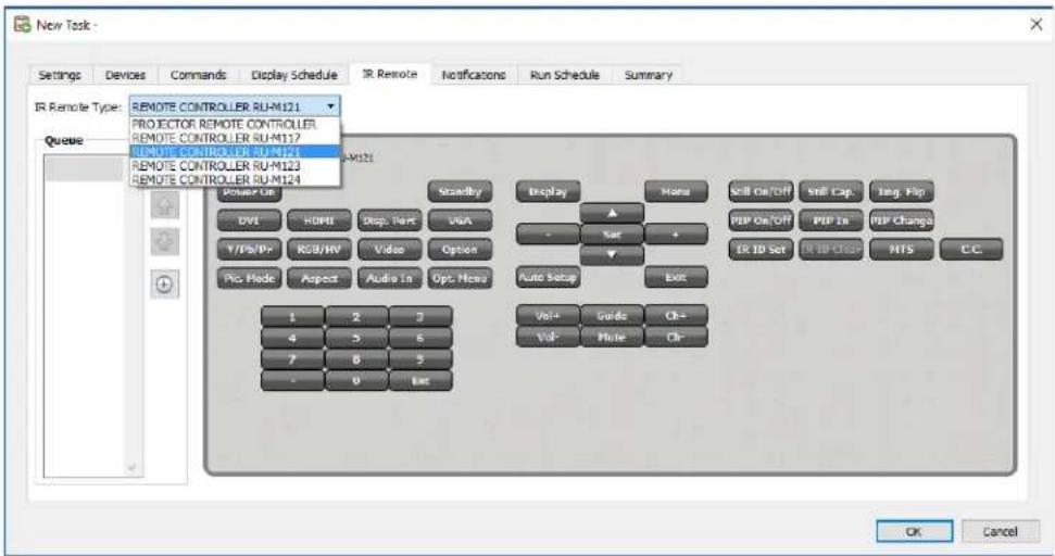
Sending IR Remote commands can be used to perform commands and access functions that may not be available via the commands in the Commands tab, but are available on the device's IR Remote control.
There are several remote controls in the IR Remote Type list; one for projectors and one for each model of the large-screen display remote. The IR remote type displayed is based on the selected models in the Devices tab. A different IR remote can be used for a task by selecting it from the IR Remote Type list.
Select the appropriate remote for the device being controlled before adding any commands.

Note: IR Remote commands for different remote types cannot be used together in the same task.
Click on the buttons in the simulated IR Remote to add them to the queue to be sent by the Task. Once buttons have been added to the queue, the sequence in which they will be sent can be rearranged or deleted using the queue arrangement , and buttons.

Note: Not all displays support IR Remote commands, and not all supported displays support all of the IR controls shown. No status or warning messages are displayed if a display does not support a particular IR Remote command.
Notifications Tab
Notifications allow the application to inform someone of the status of a task while they are away from the computer that NaViSet Administrator is running on. For example, an administrator may want to be notified when a very long task involving hundreds of devices has completed, or if an error occurred during the operation.
Select the Notifications tab to configure the settings to be notified via email about the status of a task.

Note: The Outbound Email Settings must be configured and enabled in the application Preferences in order for notification emails to be sent.
First, click Add a Notification and select Email Message in the Notification Type list.
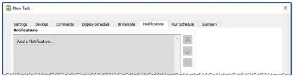
In the Notification Settings dialog, enter the recipient's email address. Insert a semicolon between addresses if multiple email addresses are required. A supplemental message to be added to the automatically generated message text can also be entered. Click OK when finished.
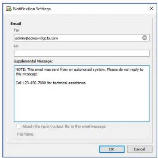
Next, select the types of notifications to be sent.
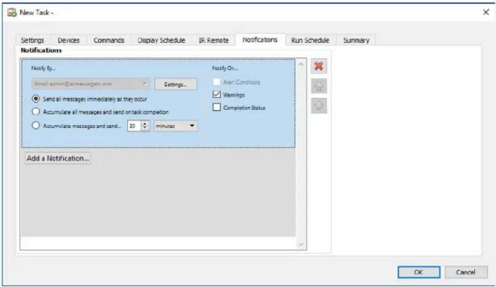
Options are:
- Alert Conditions - Are only available when using Conditional type tasks, and are sent when the conditions specified in the task become true.
-Warnings - Are sent for the following conditions:
Connection error
Device might not be powered up
- Control or setting cannot be set or read
- Task overrun
Completion Status - Is sent once the task has completed.
To avoid a possible overwhelming number of messages being sent, message delivery can be controlled as follows:
- Send all messages immediately as they occur
- Accumulate all messages and send on task completion
- Accumulate messages and send every [user definable period]

Note: Multiple notifications can be added to each task. This is useful if different recipients for different types of notification conditions are necessary. For example, one person may only want to be notified when a task completes, but another person may want to be notified if there is any kind of alert or warning when a task runs.
Run Schedule Tab
Next, click on the Run Schedule tab. This tab is used to set how and when the task is started. Tasks can be set to run On Demand (manually started), or using a Schedule, or as Temporary (one time task that will not be saved to the Task Library).
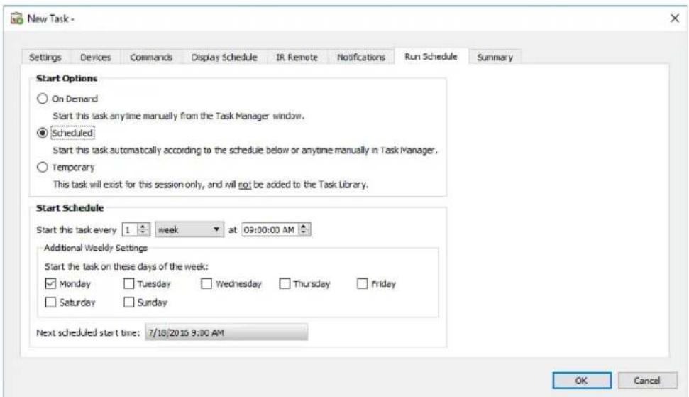
To schedule the task to run at specific times or intervals, click Scheduled and select the desired Start Schedule settings. The next time that the Task will be automatically started is shown.

Note: A task will not start if its task properties dialog is opened at the same time that it is scheduled to start. Instead, it will be rescheduled for the next start time when the dialog is closed.
Summary Tab
Next, optionally click on the Summary tab to review all of the settings for the new task. Click OK to add the newly created task to the list of tasks. The new task will be added to the task library and will also be listed in the Inactive Tasks table in the Task Manager.
Creating Conditional Tasks
Conditional Tasks are created in the same way as other types of tasks and are typically used to warn of abnormal conditions in a device, or if a particular setting has changed. See the previous example for how to create a new task.
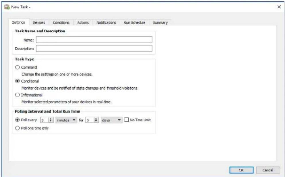
Select Conditional as the Task Type. Since this type of task is typically used to actively monitor a condition, the Polling Interval and Total Run Time options are enabled for specifying how often the condition(s) should be checked while the task is running.
The Polling Interval sets how often the devices are polled, and the Total Run Time specifies how long the task should keep polling once the task has been started. If the task is to run continuously until it is stopped by the user, select No Time Limit. Select Poll one time only if the task is to perform just one query and then stop.

Note: Each task takes some time to complete, so care should be taken not to set a polling interval that is shorter than the time it takes to poll all of the devices in the task. If a task is due to poll again before the previous poll has completed, a warning message "Last Query Still Running" will be generated and the polling of all remaining devices will be skipped for that polling interval.
Next, select the Devices tab and select the devices that the task will be performed on.
Next, select the Conditions tab and select the device controls that are to be checked. The list of available controls will depend on the type of device(s) selected. Click on a control to add it to the list of conditions.

Note: Not all devices will support all of the controls listed.
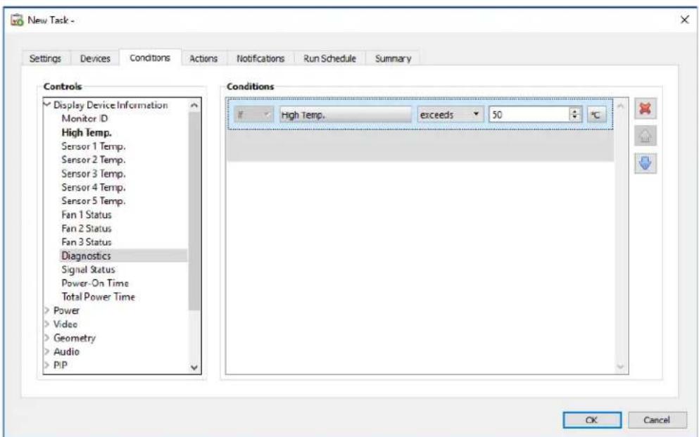
For each control that is added, an associated condition must be set. If this condition is met then a notification and/or alert will be issued. Depending on the type of control selected, different conditions will be available.
| Control Value Type Available Conditions Examples | ||
| Numerical value | Exceeds, Falls Below, Changes | Temperatures, Fan Speed, Human Sensor, Ambient Light Sensor |
| Binary or Named value | Is, Is Not, Changes | Diagnostics, Video Input, Power State |

Info: A "named" value is a control setting that has discrete selections; for example, the Video Input control has named values of Video, HDMI, DisplayPort, etc. A "binary" value has two states, such as On and Off.

Note: The same limitations on control values as described in the Note on page 88 applies to Conditions. The values used to evaluate conditions may be different from the On Screen Display values.
If more than one condition is added, the operand used to evaluate the alert condition can be selected. AND and OR operands are available. These operands apply to all conditions applied in the task.
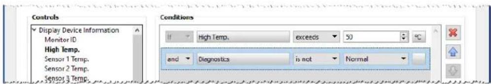
If a selected device doesn't support a control, a warning will be issued when the task runs on the device.
Actions Tab
Next, select the Actions tab and optionally specify what action should occur when a conditional task generates an alert. For example, if the conditional task is set to send an alert if a display's temperature exceeds 80^ C, an action can be created that will send a command to reduce the backlight brightness level if that alert occurs.
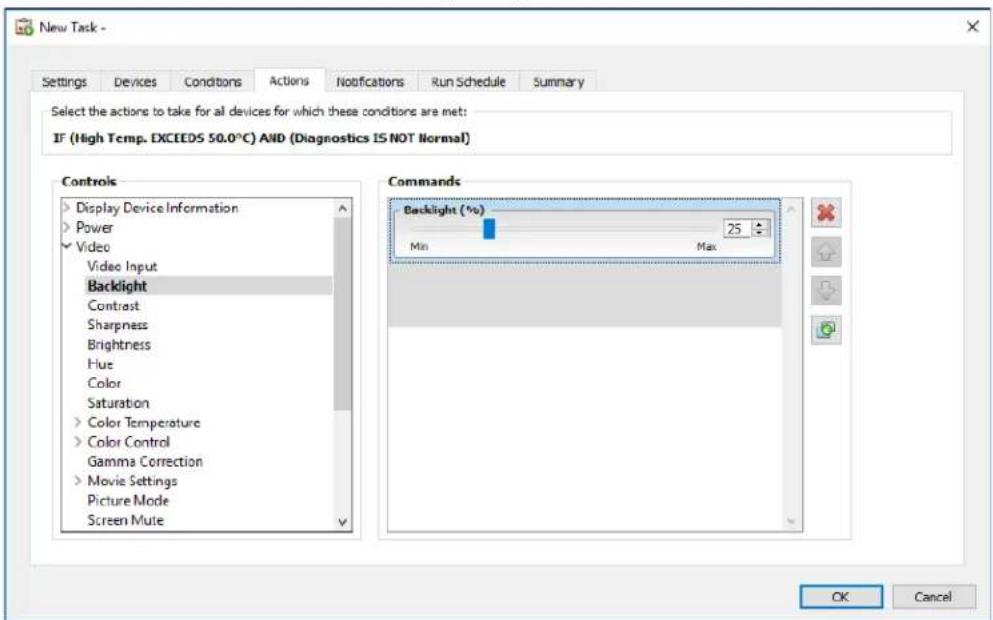
Next, optionally select and complete the Notifications and Run Schedule tab in the same way as the previous example. Click OK to add the newly created task to the list of Inactive Tasks.
Creating Informational Tasks
Informational Tasks are created in the same way as other types of Tasks and are used to actively monitor one or more device parameters.
Select Informational as the Task Type.
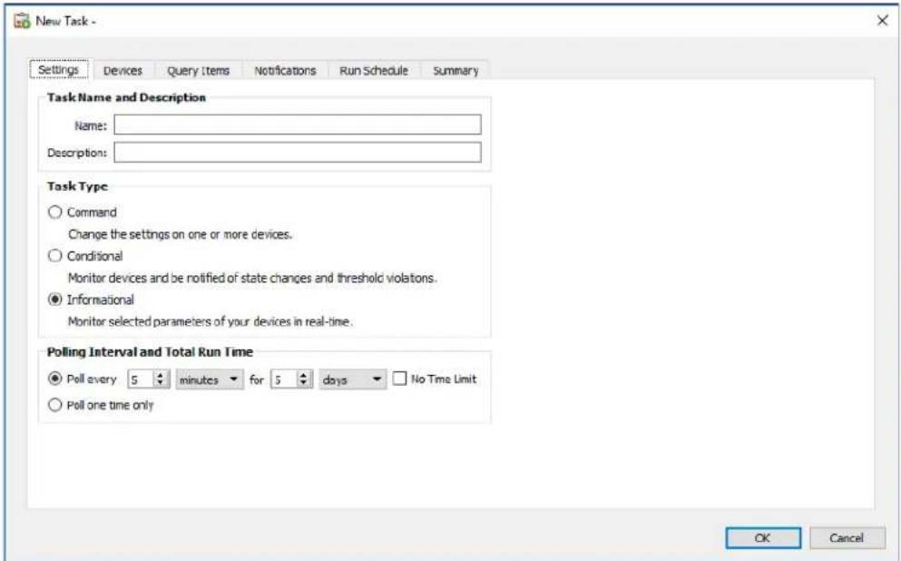
Since this type of task is typically used to actively monitor a parameter, the Polling Interval and Total Run Time are enabled and specify how often the condition(s) should be checked while the task is running.
The Polling Interval sets how often the devices are polled, and the Total Run Time specifies how long the task should keep polling once the task has been started.

Note: Each task takes some time to complete, so care should be taken not to set a polling interval that is shorter than the time it takes to poll all of the devices in the task. If a task is due to poll again before the previous poll has completed, a warning message "Last Query Still Running" will be generated and the polling of all remaining devices will be skipped for that polling interval.
Next, select the Devices tab and select the devices that the task will be performed on.
Next, select the Query Items tab and select device controls that are to be monitored.
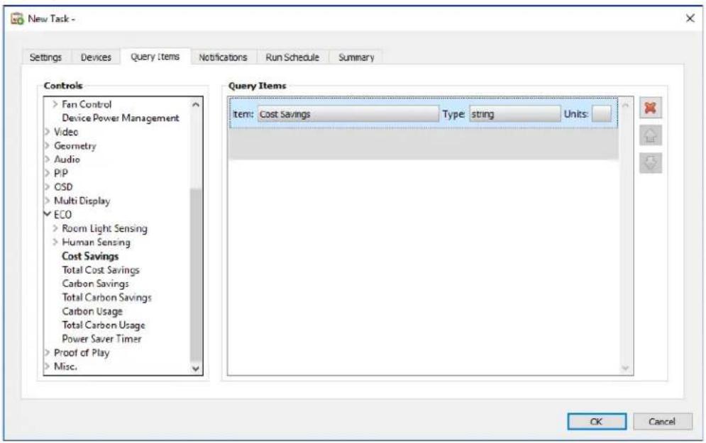

Note: The list of available controls will depend on the type of device(s) selected. Not all devices will support all of the controls listed. The same limitations on control values as described in the Note on page 88 applies to the control values read from devices. The values shown may be different from the On Screen Display values.
Next, select and complete the Notifications and Run Schedule tabs.
Click OK to add the newly created task to the list of tasks.
While any task is running, the results can be viewed in real time by clicking the Watch button in the Active Task list. A Task Viewer window will be opened that shows each device and query. The queries for individual devices can be filtered by selecting the device from the Query Results list.
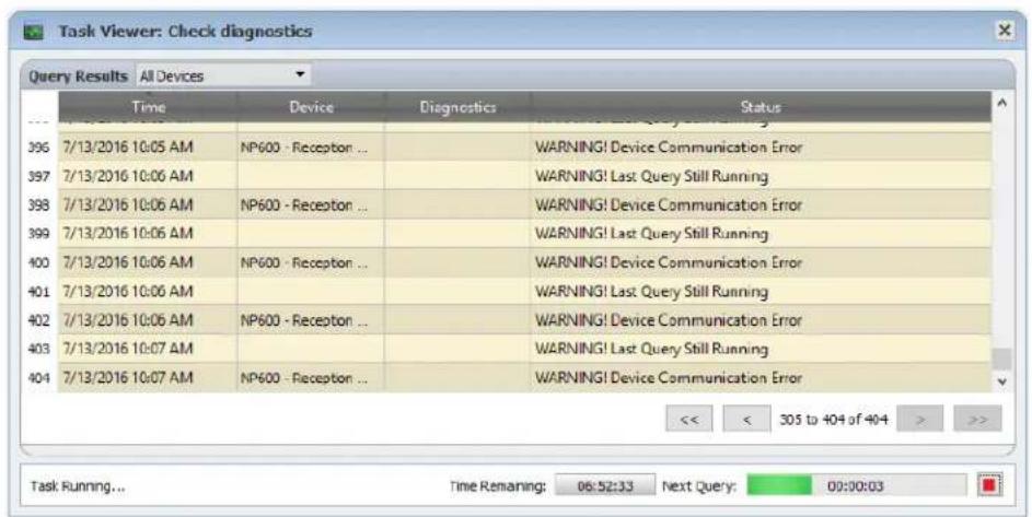

Task History
The Task History window shows the operation history for a particular Task. To view the Task History, click the button for a task in the Inactive Tasks list, or select the desired tasks and click History... from the Task Library dialog.
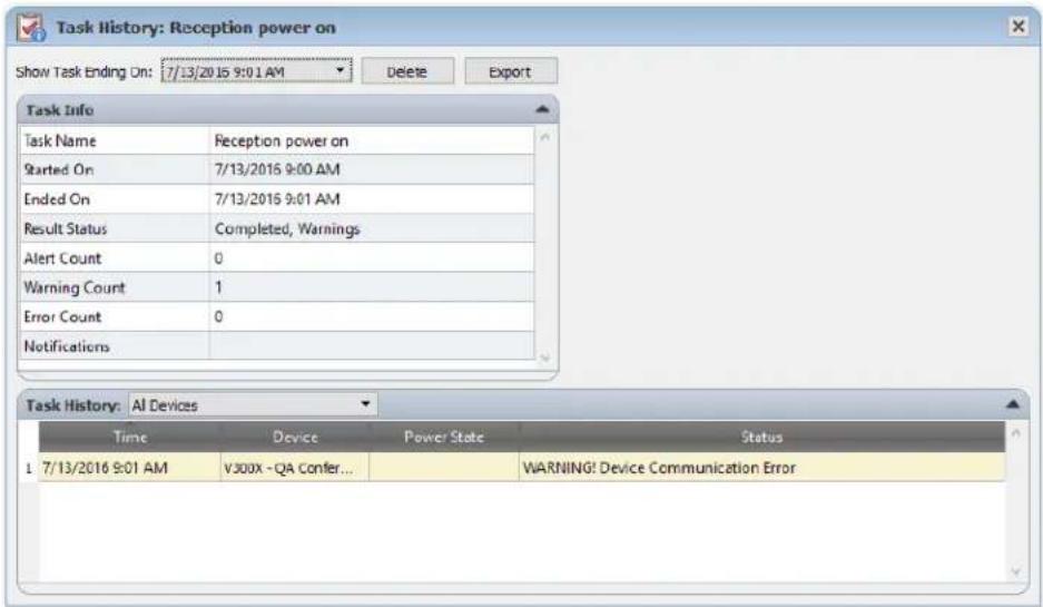
The history for each time the task has been run can be selected in the Show Task Ending On: list. The Task Info list shows a summary of the task results, including the number of alerts, errors and warnings that were encountered. The Task History list shows the results for each device in the task. The list can be filtered by device name by selecting a device from the listbox.
Note:
- More detailed information about a device in the list can be seen by mousing the cursor over the device column.
- Clicking on a row will automatically select the corresponding device in the Device Tree.
Double-clicking a row will select the device and open the Device Properties window for the device.
The history for the currently selected task run can be exported via the clipboard, Excel or delimited text file by clicking the Export button.
The history for the currently selected task run can also be deleted by clicking the Delete button.

Proof of Play
Some NEC large-screen display models have the ability to detect and record to an internal event log, any changes which have an affect on the audio or visual content being presented such as a change in video or audio input, or loss of video or audio signal, or a detectable internal failure. This event log provides verification and reassurance that the display was powered on and correctly showing a particular video input at a particular time. This feature is called Proof of Play.

Note: Not all large-screen displays support Proof of Play. See the README files for details. For the operations described in this section to be enabled at least one device that supports Proof of Play must exist in the device tree.
Whenever one of these changes occurs, it is saved within the device along with the date and time and a number of other status parameters. Collectively, this is referred to as a Proof of Play Event.
Note: Each event is time stamped using the display's internal Real Time Clock (RTC), allowing direct comparisons to be made with media playlists, and other events. So it is important to make sure that the RTC is set correctly. This can be done via a task as described in "Sync Clock with System Date/Time" on page 77.
Because the display itself creates a log for each internal event that occurs, it is not necessary to continuously poll each display in order to try and detect an event as it occurs. The log in each display can be read at much larger intervals – thus reducing the network burden.
A Proof of Play Event consists of the following data:
| Status Parameter/Setting Examples | |
| Date/Time 3/30/2015 9:17:05 AM | |
| Video Input DVI, HDMI1 | |
| Video Resolution 1920x1080, | 1280x720 |
| Video Signal OK, No Signal | |
| Video Status OK, Circuit Failure | |
| Audio Input HDMI1, HDMI2 | |
| Audio Signal OK, No Signal | |
| Audio Status OK, Circuit Failure | |
Depending on the display model and any installed hardware options, the following conditions may also appear in the Proof of Play Event.
| Media player started Media player data copy error | |
| Media player stopped Media player data not found | |
| Media player paused Local storage device is full | |
| Media player error Media player data read/write error | |
| Copying Media player data from USB | Human presence detected |
| Copying Media player data from network folder | No human presence detected |
| Media player data copy completed successfully | Power loss detected |
NaViSet Administrator provides a special built-in task for managing Proof of Play operations and tools for viewing and exporting Proof of Play Events.
Configuring Proof of Play
Proof of Play is configured using the Proof of Play Task Properties dialog, opened by selecting Proof of Play... in the Tasks menu.
When the dialog is opened for the first time, the Devices tab will be selected. Select one or more devices or groups of devices to include. Only those devices that support Proof of Play will be enabled.
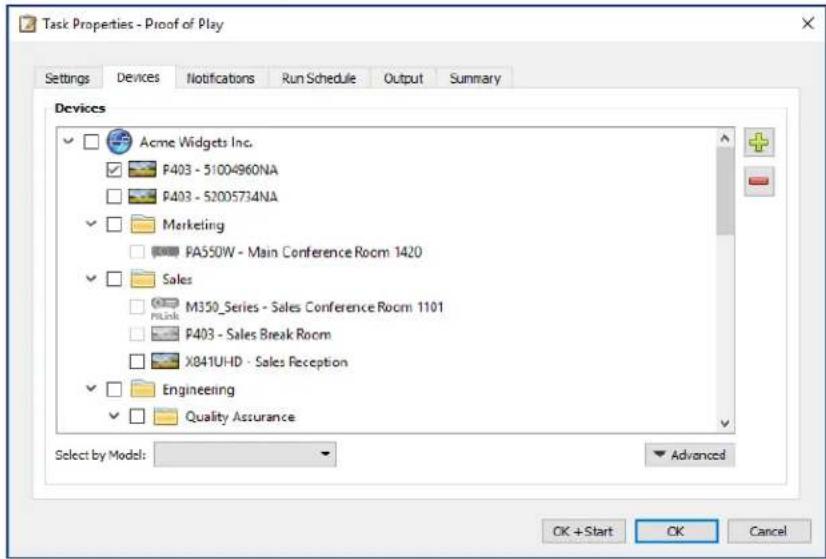

Note: The selection of one or more devices is all that is required to start using Proof of Play. The remaining settings described in this section are optional.
In the Settings tab, select the conditions in which to trigger alert messages should they occur. See "Alerts list" on page 84 for more information about alerts.
No Video Signal - No video input signal detected
Video Circuit Failure - The device hardware failed to produce a picture
No Audio Signal - No digital audio input signal detected
Audio Circuit Failure - The device hardware failed to produce sound
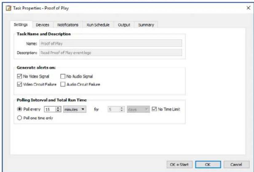
The Polling Interval sets how often the devices are polled, and the Total Run Time specifies how long the task should keep polling once the task has been started. If the task is to run continuously until it is stopped by the user, select No Time Limit. Select Poll one time only if the task is to perform just one query and then stop.
Determining Polling Time Interval
There is a limit to the number of Proof of Play events a device can store internally. Whenever this limit is reached the device simply replaces the oldest event with the newest one. When configuring Proof of Play it is important to consider the polling time interval to ensure no events are overwritten within the display before they are polled by NaViSet Administrator.
Important points to consider:
- NaViSet Administrator has no limit to the number of events that can be stored in the database.
A single poll will read all of the events currently stored in the display.
All of the events stored in the display will be erased after each poll.
The Proof Of Play events in the display will be lost if AC power is removed, or if the display is turned off. Therefore, displays should be polled before sending a Power Off command.
The default polling interval of 15 minutes should be reduced in the following cases:
The expected number of event changes of any device may exceed approximately 100 events every 15 minutes.
- Users need to be notified of alert conditions sooner than (up to) 15 minutes after the alert condition occurs.
The default polling interval of 15 minutes can be extended in the following cases:
The above issues are not a concern.
The time to query all of the devices can exceed 15 minutes. This can occur with high numbers of devices or when other tasks are running concurrently.
Proof of Play records can be output to a text file or Excel spreadsheet as they are read (in real-time). In the Output tab, check Output to File, click Select... and select a file name and type. The following file formats are supported:
Excel spreadsheet in .xls or .xlsx format
Tab delimited text file
Comma delimited text file
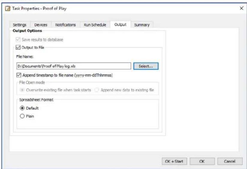
Choose Overwrite existing file when task starts to create a new output file every time the task is started. If the file already exists it will be deleted. To append new records to an existing file, select Append new data to existing file.
To prevent output files from being overwritten, select Append timestamp to file name to have the date and time the file is created included in the file name.
If a spreadsheet file type is selected, the formatting of the spreadsheet can be set to either Default or Plain. The Default formatting applies cell coloring to make data easier to read.
Select the Notifications tab to configure the settings to be notified via email about the status of the task. See"Notifications Tab" on page 92 for more information.
Select the Run Schedule tab to set how and when the task is to be started. See page "Run Schedule Tab" on page 94 for more information.
Click the Summary tab at any time to review all of the current settings.
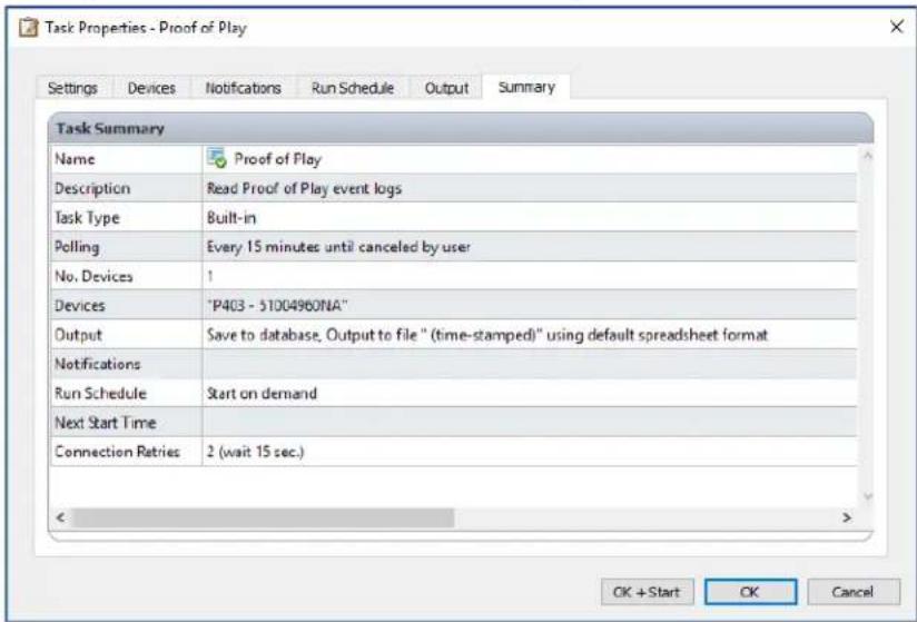
Click OK to save the settings and close the dialog box. Click OK + Start to start the Proof of Play task immediately after the dialog box is closed.
Once configured, the Proof of Play task will be visible in the Task Manager and operates like any other task in NaViSet Administrator.
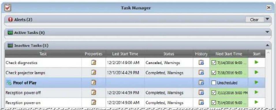
Event Log Window
The Proof of Play Event Log window shows all events currently stored in the database. The task can also be started and stopped from this window. To open the Proof of Play Event Log window, select Proof of Play Event Log in the View menu.
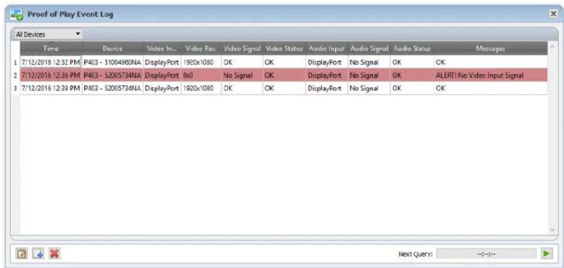
- Rows containing alert messages will have a red background.
To show the events for only one device, select the device from the drop-down list located near the upper-left corner of the window. - Click to open the Proof of Play Task Properties dialog.
- Click to open the Export dialog.
- Click to clear the table and permanently delete all Proof of Play events from the database.
- Click and to start and stop the Proof of Play task.
- Double-clicking on a row will open that device's properties window to the POP tab page, where the matching row will be automatically selected.
POP Tab
For devices supporting Proof of Play, a POP tab will be included in the tab bar of the Device Properties Window. The POP tab page is similar to the event log window, but shows the events only for that device.
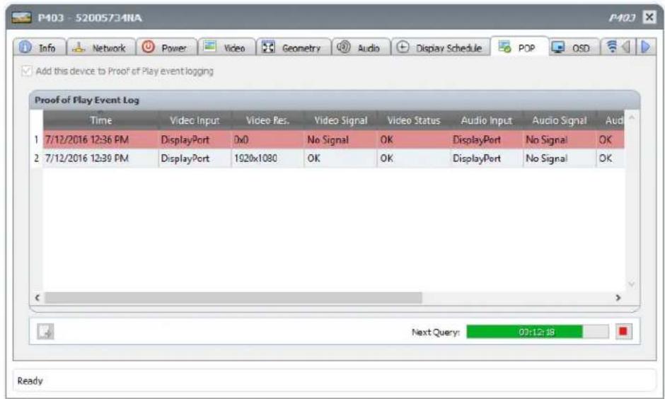
- Check the Add this device to Proof of Play event logging box to add this device to the Proof of Play task, or uncheck to remove the device.
- Click to open the export dialog.
- Click and to start and stop the POP task.

Reports
About Reports
Reports are operations that gather selected setting values and information from one or more devices, and create a report of the results.
These operations can be performed either in real-time (meaning devices are queried when the operation is run), or using information stored in the database for each device. A hybrid query that will only query devices if the data in the database is older than a given time period can also be specified. This option is useful to reduce unnecessary real-time queries on devices, since they are much slower than querying the database.
The results of a report can be saved to the database, and also to an output file such as an Excel spreadsheet, or delimited text file. When saved to the database, the report results can be viewed at any time using the Report History viewer. Report results are stored for each time a report is generated and each can be selected, thus providing a history of the report over time.
Example uses of reports are:
- Keeping track of computers and displays within an organization, by logging the device name, model, serial number, and asset tags.
- Keeping track of the number of operating hours that displays have been in use, the carbon savings, or any other parameter or supported setting that can be read from a device.

Report Library
All Reports can be managed using the Report Library, available on the Reports menu, or by clicking on the toolbar button. Reports can be created, edited, duplicated, and deleted from within the Report Library. The execution history of a report can be viewed and exported.
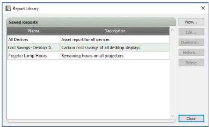

Report Manager
All Reports that have been created for the current database are listed in the Report Manager tab.
This tab shows:
Inactive Reports that are not currently running
Active Reports that are currently running
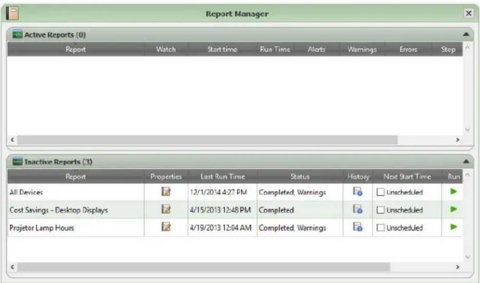

Inactive Reports list
Inactive Reports are reports that are either scheduled to run and are waiting for their start time to occur, or reports waiting to be started manually. For reports that are scheduled to run, the Next Start Time is shown with a green background. The checkbox in the Next Start Time column can be used to temporarily disable the automatic starting of a report with the schedule. Any report can be made to start immediately by clicking the Run button.

Note: A report will not start if its properties dialog is opened at the same time that it is scheduled to start. Instead, it will be rescheduled for the next start time when the dialog is closed.
The properties of a Report can be edited by clicking on the Properties button. This is the same as editing a report from the Report Library.
The history of a report can be viewed by clicking the Report History in an inactive report. This is the same as viewing the history from the Report Library. The report history shows the results of each time the report has been executed.
For reports that have executed during the current session, the Status column will include an icon next to the description indicating the overall result status. The text color of the report row will also be changed and made bold. The icons and colors used are as follows:
The report completed or was canceled without warnings or errors. Text will change to green.
A lower level warning, such as a control that is not supported by the device. Text will change to brown.
At least one error or one high level warning, such as a device connection failure. Text will change to red.
A context menu providing quick access to common report operations can be opened by right-clicking on the report. The context menu provides these actions:
Library - Opens the Report Library with the report selected.
Properties - Opens the Report Properties dialog for review or editing.
Schedule - Opens the Report Properties dialog with the Run Schedule tab selected.
History - Opens the Report History Viewer.
Run - Starts and runs the report.
Clear History - Permanently deletes all report history information.
× Delete-Depeltes the report.
Active Reports list
Active Reports are reports that are currently being run. For Database Report types, where all of the information is being queried from the current database, a report may be active for only a fraction of a second while it is processed. Real-time Reports may take up to several hours to process depending on the number and type of networked devices that are being queried. Once an Active Report has completed being processed, it will be moved to the Inactive Report list.
While a report is active, the progress of the report can be viewed in real-time by clicking the Watch button. An Active Report can also be manually stopped by clicking the Stop button.
The number of alerts, warnings or errors that occur while a report is running are shown.
Creating Reports
Reports can be created by selecting New Report... on the Reports menu, or by clicking the New Report toolbar button, or by selecting New... from the Report Library.
Settings Tab
First, give the report a Name and Description so it can be identified easily in the Reports list.
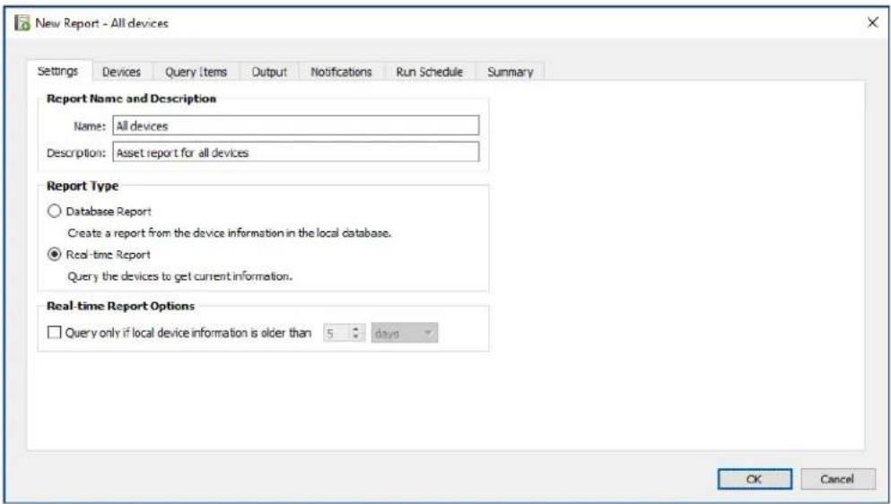
Next, select the type of report to be created.
Database Reports: Use the current information for each device stored in the database to create a report. This operation is very fast as no devices are queried, however, the information may not reflect the current condition of each device. The Time Stamp column, added to reports by default, lists the date and time when the information for each device was last updated.
Real-time Reports: Queries devices to gather the latest setting values and information. This can be selected to always query the devices, or only query a device if the information in the database has not been updated within a selectable time period. This is useful in order to minimize the number of device queries that are made, while at the same time keeping the device information in the database up to date.

Note: If a device cannot be accessed during a Real-time Report (for example, if it is powered off, disconnected, network configuration settings have changed, or is otherwise inaccessible), the icon shown in the device tree will change to show a warning symbol. In this case, the most recent information from the database for the device will be substituted in the report.
Whenever database data for a device is substituted in a report because the device could not be accessed, a message "WARNING! Data May Be Out of Date" will be shown in the report's Status column for the device. The Time Stamp column of the report indicates the date and time of each query or database record for the device.

Info: When a real-time report is performed on a device, the database information for the device is automatically updated with the equivalent of performing a Standard Refresh. As a result any new displays connected to a Windows computer will also be automatically detected and updated.
Devices Tab
Next, select the Devices tab and then select the devices to be included in the Report. Selecting a group will automatically select all of the devices within that group.
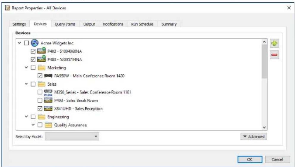

Note: Windows computers and daisy chained large-screen displays are shown in the device tree in the Devices tab without any child devices (attached displays for Windows computers, and individual daisy chained large-screen displays for daisy chain hosts). These child devices will be determined when the Report operation is actually run, and automatically added to the report.
Query Items Tab
Next, select the Query Items tab. The list of controls contains all of the information and settings that can be gathered from the types of devices that have been selected.
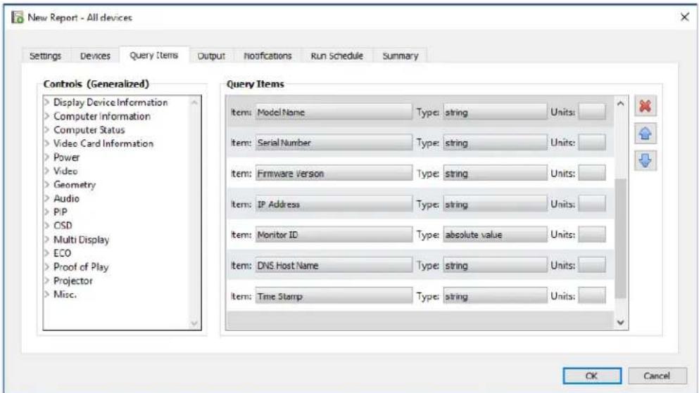
The Query Items list contains all of the items to be queried for the selected devices. The order of the items in a report can be changed and items can be removed using the , , and × buttons. Some query items are automatically included by default as they are necessary to uniquely identify each device in the report. The automatic query items cannot be removed but can be reordered; they are highlighted in red for easy identification.
Click on a control in the list to add it to the Query Items list.

Note: Not all devices will support all of the controls listed.
Output Tab
Next, select the Output tab. The results of a query can be saved to the database by selecting Save results to database. This allows the results of a particular query to be viewed later in the Report History. If this option is not selected then the results of the query will only be available in the output format selected.
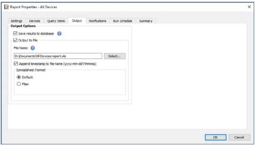
The results of a query can also be saved to a file in any of the following formats by selecting Output To File and clicking Select... and selecting an output file name and type:
- Excel spreadsheet in .xls or .xlsx format
Tab delimited text file
Comma delimited text file
To prevent output files from being overwritten, select Append timestamp to file name to have the date and time the file is created included in the file name.
If an Excel spreadsheet is selected, the formatting of the spreadsheet can be set to either Default or Plain. The Default formatting applies cell coloring to make data easier to read.

Note: If the Preferences setting Open report files on completion is selected, then the default application associated with the selected file type will be used to open the file once the report has completed.
Notifications Tab
Select the Notifications tab to configure the settings to be notified via email about the report.

Note: The Outbound Email Settings must be configured and enabled in the application Preferences in order for notification emails to be sent.
First, click Add a Notification and select Email Message in the Notification Type list.
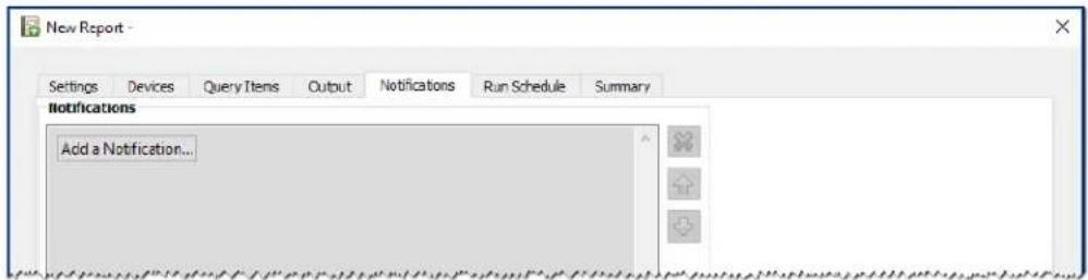
In the Notification Settings dialog, enter the recipient's email address. Insert a semicolon between addresses if multiple email addresses are required. A supplemental message to be added to the automatically generated message text can also be entered.
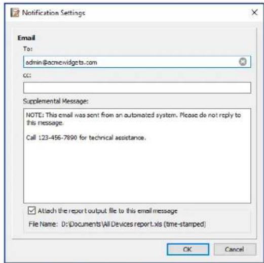
Select Attach the report output file to this email message to have the report's output file sent with the notification email message.
Click OK when finished filling in the email notification settings.
Next, select the types of notifications to be sent.
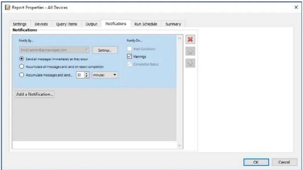
-Warnings - Are sent for the following conditions:
Connection error
Device might not be powered up
Control or setting cannot be set or read
Completion Status - Is sent once the report has completed.
To avoid a possible overwhelming number of messages being sent, message delivery can be controlled as follows:
- Send all messages immediately as they occur
Accumulate all messages and send on report completion - Accumulate messages and send every [user definable period]

Note: Multiple notifications can be added to each report. This is useful if different recipients for different types of notification conditions are necessary. For example, one person may only want to be notified when a report completes, but another person may want to be notified if there is any kind of alert or warning when a report runs.
Run Schedule Tab
Next, click on the Run Schedule tab. This tab is used to set how and when the report is started. Reports can be set to run On Demand (manually started), or using a Schedule, or as Temporary (one time report that will not be saved to the Report Library).
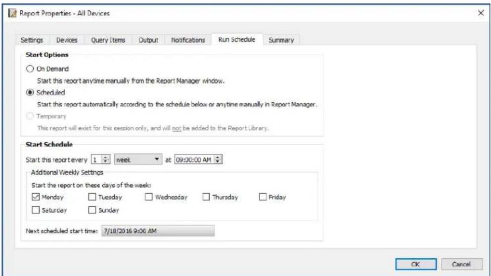
To schedule the report to run at specific times or intervals, click Scheduled and select the desired Start Schedule settings. The next time that the report will be automatically started is shown.

Note: A report will not start if its properties dialog is opened at the same time that it is scheduled to start. Instead, it will be rescheduled for the next start time when the dialog is closed.
Summary Tab
Next, click the Summary tab to review the settings for the new Report. Click OK to add the newly created report to the list of reports. It will appear in the list of Inactive Reports.

Report History
The Report History window shows the operation history for a particular report. To view the Report History, click the History button for a report in the Inactive Reports list, or select the desired report and click History... from the Report Library dialog.
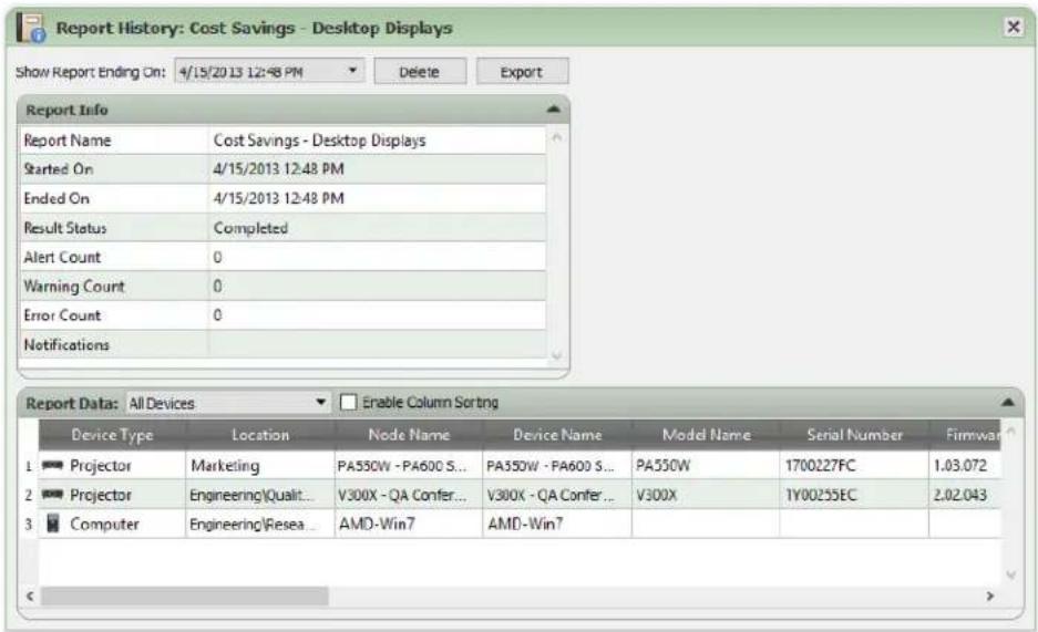
The history for each time the report has been run can be selected in the Show Report Ending On: list.
The Report Info list shows a summary of the report results, including the number of alerts, errors, and warnings that were encountered.
The Report Data table shows the results for each device in the report. The table data can be filtered by device type by selecting a type from the Device Type listbox.
Note:
- Clicking on a row will automatically select the corresponding device in the Device Tree.
Double-clicking a row will open and select the device tab.
Report History can be sorted by column, by selecting Enable Column Sorting and then clicking on the header of the column to sort by. The sorting order can be reversed by clicking on the column header again.
History for the currently selected report run can be exported via the clipboard, Excel or delimited text file by clicking the Export button. To prevent output files from being overwritten, select Append timestamp to file name to have the date and time the file is created included in the file name.
History for the currently selected report run can also be deleted by clicking the Delete button. History for a Report is retained until it is deleted.
Chapter
9
Preferences
About
The Preferences dialog is used to configure many of the application settings and is accessed from the Tools menu. Preference settings are grouped into pages which are selected using the icons on the left of the window. Click Reset to restore the default values for all of the settings on the currently selected page.
General Settings
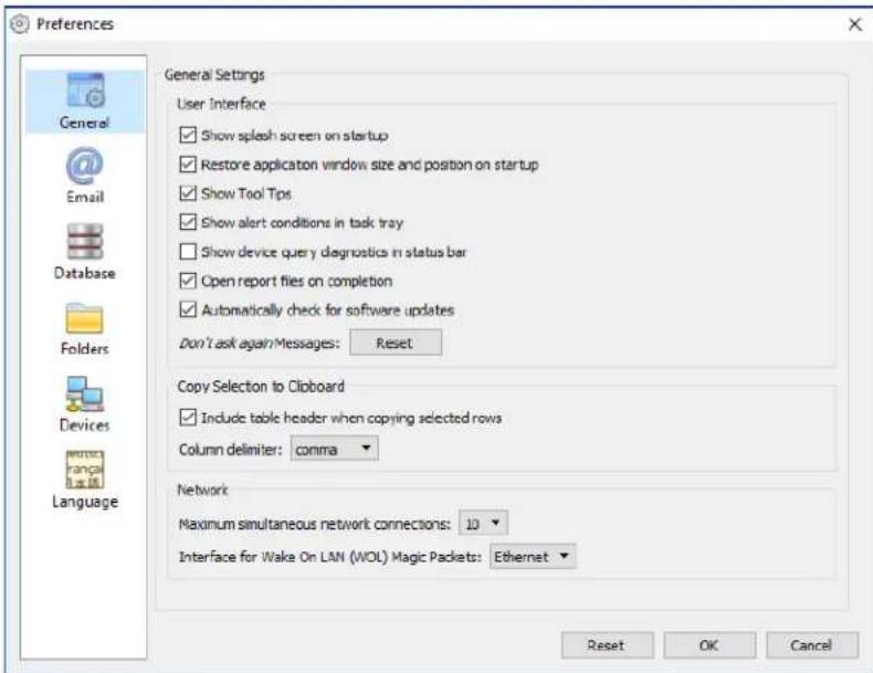
- Show splash screen on startup - When selected, a splash screen will be shown briefly when NaViSet Administrator is started.
- Restore application window size and position on startup - Saves and restores the application's window size and position.
-
Show Tool Tips - When selected, Tool Tips for various controls within the application are shown when the cursor is moused over the control.
-
Show alert conditions in task tray - If an alert condition occurs, a popup message will be shown in the Windows Task Tray (Windows version), or the Status Menu (macOS version).
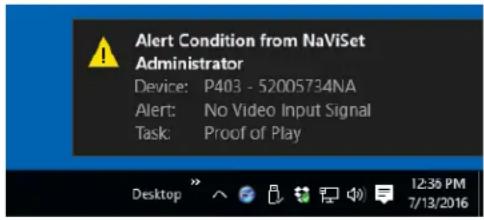
- Show device query diagnostics in status bar - When selected, the status bar in the main window will show a summary of the number of connections to different devices that are currently being processed, and the number of pending connections that are waiting either for an available connection, or for another connection to the same device to be completed. The Maximum simultaneous network connections setting sets the limit for the number of connections that can be used at one time.

Note: Only one connection per device is allowed at a time. Therefore, if there are two or more separate operations to be performed on a device, only one will be current and the others will be pending until the running job has completed, at which point a pending connection will become current.

- Open report files on completion - When selected, the output file (Excel or delimited text file), or Report History window (if no output file is specified) will be automatically opened when a Report operation has completed.
- Automatically check for software updates - When selected, the application will periodically automatically check to see if a newer version is available by querying the NEC update servers. An Internet connection is required.
- Don't ask again messages: Reset - Restores the displaying of any messages that may not be being shown because Don't ask again was selected when they previously appeared.
- Maximum simultaneous network connections - Sets the maximum number of network connections that can be made to different devices on the network. NaViSet Administrator can communicate to multiple devices in parallel, which speeds up operation by allowing simultaneous connections, and allows more operations to be performed while waiting for other devices to respond to commands. 5, 10, 20, or 30 connections can be selected, and the default value is 10 connections.

Note: In general increasing the number of network connections increases the overall speed at which operations on a large numbers of devices can be performed. However, there is a point where more connections does not give an increase in speed due to the speed of the computer and other factors.
- Interface for Wake On LAN (WoL) Magic Packets1 - When using NaViSet Administrator to remotely wake up a computer using the WoL protocol, UDP packets are broadcast from the network adapter. If the computer running NaViSet Administrator has multiple network interfaces, such as wired and wireless, the interface to broadcast the WoL packets from can be selected.

Note: In order for Wol to work correctly, UDP port 9 must not be blocked by any firewalls or routers. See Appendix B on page 145 for details on configuring Wol.
Email Settings
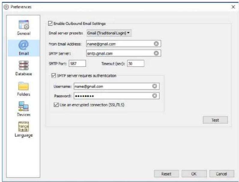
-
Enable Outbound Email Settings - When selected, NaViSet Administrator will enable the sending of notifications via email. Notifications are used in Tasks to broadcast conditions such as Alerts, Errors,Warnings, and Completion of a particular Task. When not selected, all email notifications are disabled.
-
Email server presets - This list allows for easy configuration of the email server settings for several popular email services. Selecting one of these options will pre-fill the SMTP server name for that service provider. If the email service provider is not in the list, or if the SMTP server being used is an private server, select the server preset "Other" and input the SMTP server name. The port, authentication requirement, and use of SSL/TLS are also pre-configured. The From Email Address must be entered. Depending on the selected email server preset, either NaViSet Administrator must be granted permission to use the account or the username and password must be entered for SMTP server authentication. After configuring the options, be sure to Test for correct operation since email service providers may change these parameters without notice.
Secure Login options - The service provider's authorization settings are used to grant permission to use the application with the specified account. Selecting one of these options and clicking on OK or Test will open a secondary window for logging into the account. After successful login, select the option to allow NaViSet Administrator to use the account. The service provider may require an additional verification step, follow the instructions on-screen to complete the authorization process. The account email address and password are not stored in NaViSet Administrator.
Traditional Login options - The account email address and password for accessing the SMTP server are stored in NaViSet Administrator.
From Email Address - This is the email address from which messages sent by NaViSet Administrator will be sent.
- SMTP Server - This is the SMTP (Simple Mail Transfer Protocol) server to be used to send the email.
- Port: - This is the port to be used to contact the SMTP server. Note that some Internet Service Providers may block certain ports such as 25 used for sending email. Check with your SMTP server to find out which ports are supported. Typically used ports are 25 and 587.
- Timeout (sec): - Specifies the timeout period when trying to send an email via the SMTP server.
- SMTP server requires authentication - Select this if the SMTP server requires that authentication credentials be provided in order to send an email. This option is not in the interface when one of the Secure Login options is selected in the Email server presets.
-Username: - The username to be used for authentication with an SMTP server. This may be in the form of an email address depending on the server. This option is not in the interface when one of the Secure Login options is selected in the Email server presets.
- Password: - The password to be used for authentication with an SMTP server. This option is not in the interface when one of the Secure Login options is selected in the Email server presets.
- Use an encrypted connection (SSL/TLS) - Select this if the SMTP server requires that the authentication credentials be encrypted by using SSL/TLS (Secure Sockets Layer / Transport Layer Security) before sending. This option is not in the interface when one of the Secure Login options is selected in the Email server presets.
Test - Confirms connectivity and credentials with the email server.
Database Settings
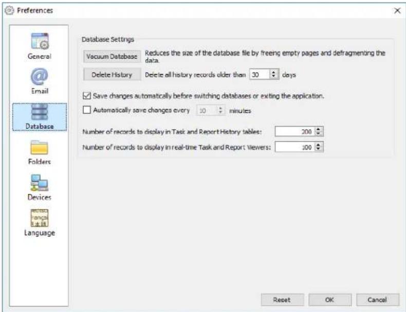
Vacuum Database - Click this button to compact the size of the database file by removing unused entries and defragmenting the data.
- Delete History - Click this button to clear the database of records older than the number of days specified. This frees up hard drive space and improves application performance. The default value is 30 days.
- Save changes automatically before switching databases or exiting the application
- Automatically save changes - Select this to have changes in the database saved at the interval specified in the "minutes" field. This reduces the chance for data loss if the application or computer shuts down unexpectedly. The default value is 10 minutes.
- Number of records to display in Task and Report History tables - Sets the maximum number of records, or rows, read from the database and shown at a time. When the number of rows in a Task or Report History exceeds this value, the table switches to paging mode, indicated by the presence of a navigation bar below the table. The default number of records to display is 200.
In the example shown below, a Task History table currently has rows 601 through 800 loaded of 8,504 total rows.

Note: Higher numbers of records can result in longer load and unload times for Task Histories, and take additional system resources such as memory and CPU time.
- Number of records to display in real time Task and Report viewers - Sets the maximum number of rows to display at a time of a running task or report. The functionality is the same as Number of records to display in Task and Report History tables. The default value is 100.
Folders
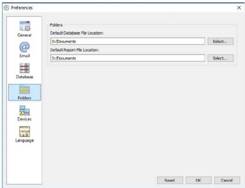
- Default Database File Location - Used to select the location where database files are stored by default.
Default Report File Location - Used to select the location where exported Report output files are saved by default.
Devices
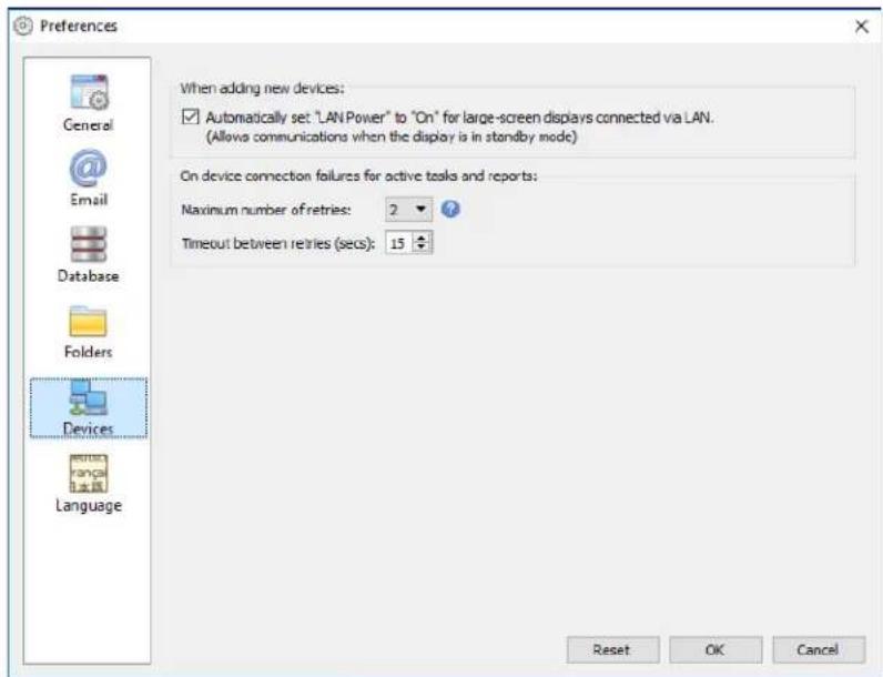
- Set LAN Power to "On" for LAN connected devices - Check this option to automatically set the LAN Power setting of NEC Large-screen displays to On as they are added to the database. This will allow communications with the display while in standby mode.
Maximum number of retries - Select the number of times running tasks and reports should attempt to connect to devices. - Timeout between retries - Enter the number of seconds to wait between each retry.

Note: The Maximum Number of Retries and the Timeout Between Retries can be overridden for each task and report. See "Devices Tab" on page 86 for more information.
Language
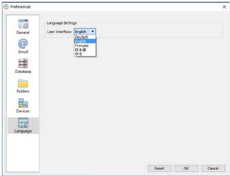
- Language Settings: User Interface - Selects the language NaViSet Administrator uses for the User Interface.

Note: After a new language is selected, NaViSet Administrator must be restarted so that the new language can be loaded. The option to restart will be given when the Preferences dialog is dismissed.

Usage examples
This chapter gives some step-by-step examples for configuring and running typical Tasks and Reports.
Example Task: Turn displays on and off at set times every weekday
In this example, displays will be configured to turn on and off at set times using two tasks; One to turn display power on, and another to turn display power off. First, a task to turn the display power on at certain times and days will be created, then duplicated, and then modified to turn off instead of on, and with the power off times.
- Create a new Task by clicking the New Task toolbar button, or selecting New Task... from the Tasks menu.
- Enter a Name and Description for the task to indicate the purpose of the task - in this case powering on displays.
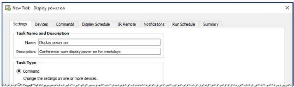
- Select the Task Type: Command
- On the Devices tab, select the devices to be controlled.
- On the Commands tab, open the Power section on the Controls list, and select Power State to add it to the list of commands.
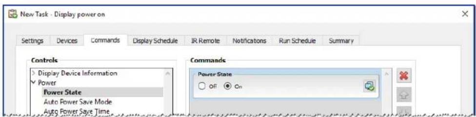
- In the list of commands, select the Power State: On.
-
On the Run Schedule tab, select Start Options: Scheduled.
-
In the Start Schedule section, select the desired time and days on which to turn the displays on.
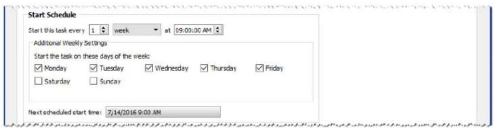
-
On the Summary tab, review the Task settings and then click OK.
-
Next, to easily configure the power off times, open the Task Library, select the task that was just created and click Duplicate...
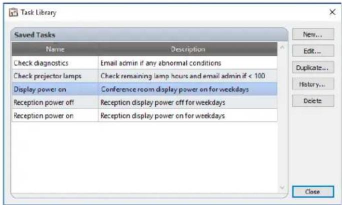
- On the Settings tab, edit the Task Name to indicate that this duplicated task is for power off.
- On the Commands tab, change the Power State command selection from On to Off.
- On the Run Schedule tab, select the desired Off time for the displays.
- On the Summary tab, review the Task settings and then click OK.
- There will now be two new tasks listed in the Inactive Tasks list that will automatically run on the selected days and times. The green background in the Next Start Time column indicates the tasks will run automatically at the time indicated.
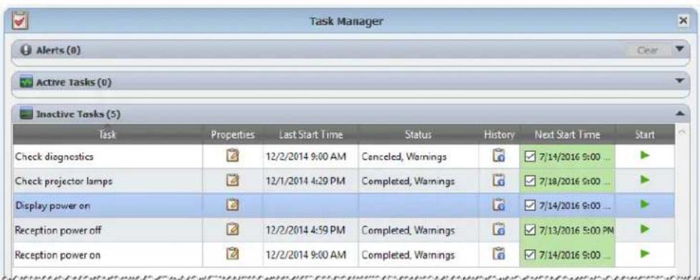
Example Task: Check for projector lamps close to needing replacement
In this example, a task to check to see if the estimated lamp life remaining for projectors is below a specified number of hours limit is created. This is recommended in order to perform proactive ordering of replacement lamps and maintenance. The task will be set to run once every week, and an email will be sent to the administrator if any projector's estimated lamp life remaining is less than 100 hours.
- Create a new Task by clicking the New Task toolbar button, or selecting New Task... from the Tasks menu.
- Enter a Name and Description for the task to indicate the purpose of the task.
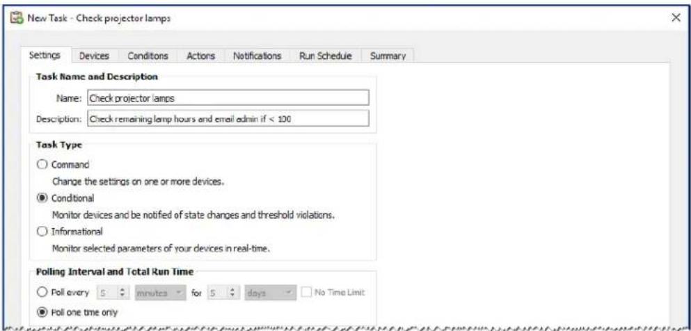
- Since the task will check the condition of a value, select the Task Type: Conditional.
- Since it is only necessary to check each projector once each time the task is run, select Polling Interval and Total Run Time: Poll one time only.
- On the Devices tab, select the projectors to be checked.
- On the Conditions tab, open the Display Device Information section on the Controls list, and select Est. Lamp Life Remaining to add it to the list of conditions.
- Change the condition to falls below and enter 100 as the hrs value.
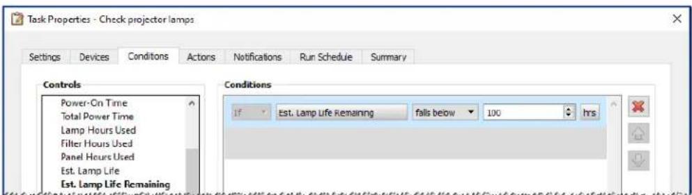
-
On the Notifications tab, click Add a Notification..., enter the recipients email address and then click OK.
-
Since the administrator doesn't need to know immediately for each individual projector if the condition is true, select Accumulate all messages and send on task completion. This way only one email will be sent listing any projectors for which the lamp lifetime condition is true.
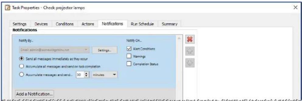
- On the Run Schedule tab, select Start Options: Scheduled and then select the frequency at which the task will be performed. In this example the task will run once a week on a Monday at 9 AM.
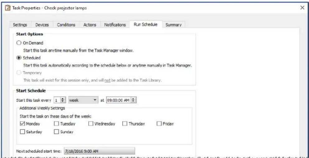
- On the Summary tab, review the Task settings and then click OK.
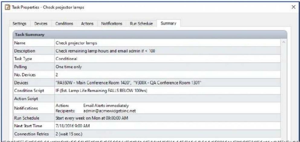
- There will now be a new task listed in the Inactive Tasks list that will automatically run on the selected day and times. The green background in the Next Start Time column indicates the task will run automatically at the time indicated.
Example Task: Check for displays reporting a diagnostic error condition
In this example, a task to check to see if a display device is reporting a diagnostic error condition is created. If a diagnostic error is returned from a device, an alert email will be sent to the administrator. The task will be set to check each device every 30 minutes during weekdays between 8 AM and 8 PM. Most NEC display devices can report diagnostic error conditions such as overheating, fan failures, lamp failures, etc. (if applicable).
- Create a new Task by clicking the New Task toolbar button, or selecting New Task... from the Tasks menu.
- Enter a Name and Description for the task to indicate the purpose of the task.
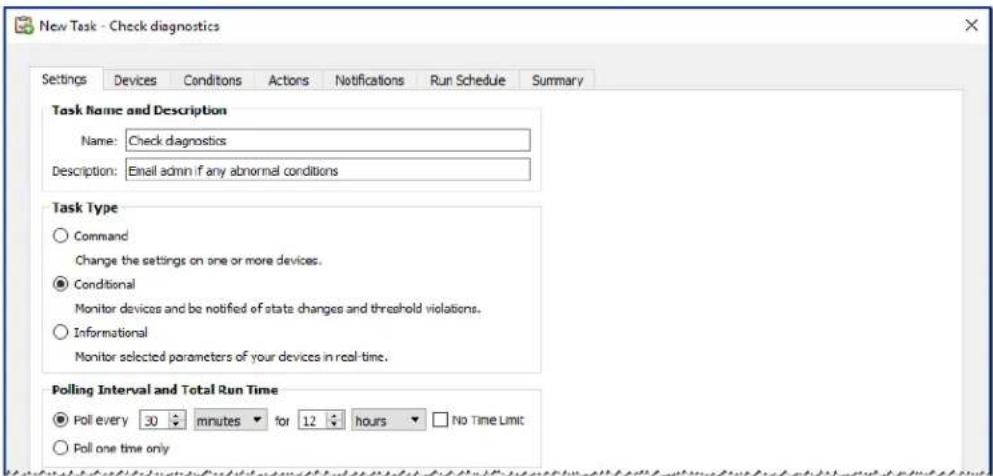
- Since the task will check the condition of a value, select the Task Type: Conditional.
- The task will check each device every 30 minutes, so set the Poll Every interval to 30 minutes. It will run from 8 AM to 8 PM, so set the run time to 12 hours.
- On the Devices tab, select the devices to be checked.
- On the Conditions tab, open the Display Device Information section on the Controls list and select Diagnostics to add it to the list of conditions.
- Change the condition to is not and Normal as the value.
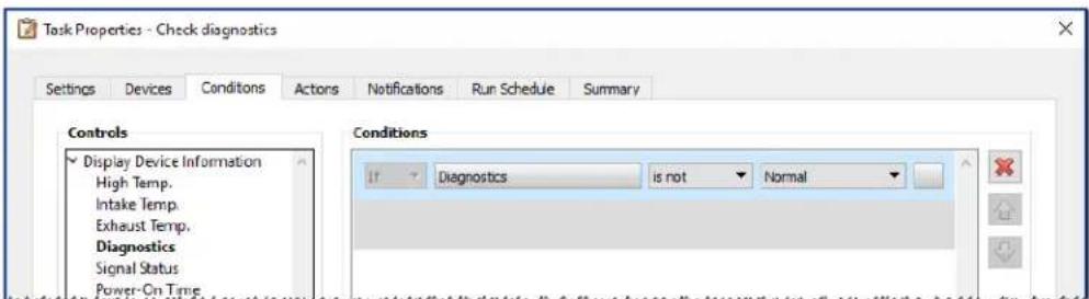
-
On the Notifications tab, click Add a Notification..., enter the recipients email address and then click OK.
-
Since the administrator will want to know immediately for each device if the condition is true, select Send all messages immediately as they occur. Since the administrator will want to be notified if a device is unable to be reached over the LAN, selectWarnings in the Notify On... section, as well as Alert Conditions. A warning will be generated if a device can't be reached for some reason.
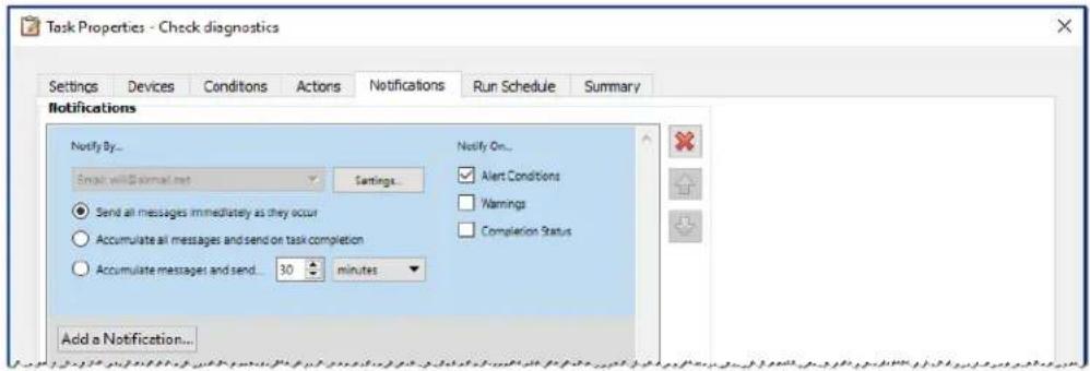
- On the Run Schedule tab, select Start Options: Scheduled and then select the frequency at which the task will be performed. In this example, the task will run on weekdays starting at 8 AM and weekends will be skipped.
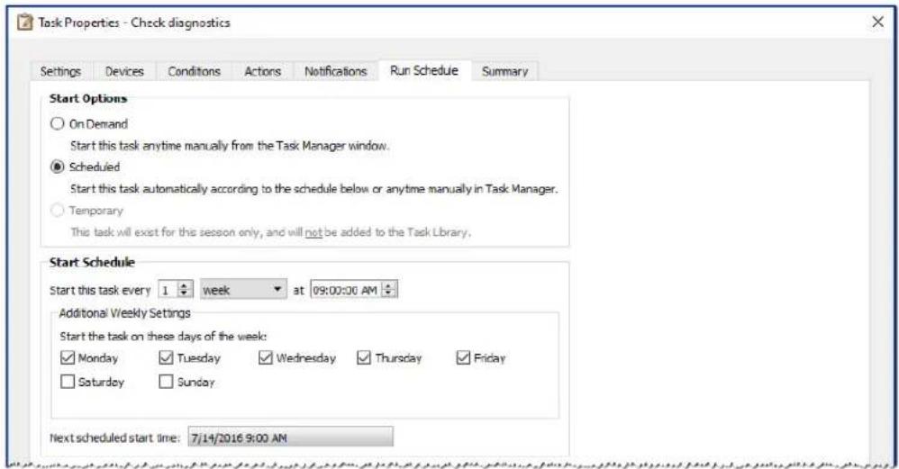
- On the Summary tab, review the Task settings and then click OK.
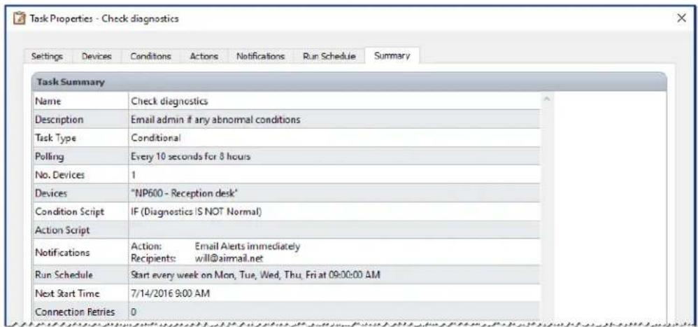
- There will now be a new task listed in the Inactive Tasks list that will automatically run on the selected days and times. The green background in the Next Start Time column indicates the task will run automatically at the time indicated.
Example Task: Configure new displays with multiple preset settings
In this example a task is created with a list of settings to be applied to displays. This could be a standard configuration that is needed for all new displays in a particular application or environment. Having these changes performed by a task means that the process can be automated, thus reducing the time taken and risk of error due to mis-adjustment.
Once a task has been created with the desired settings, it can be run on demand and applied to new displays by modifying the devices selected in the task.
- Create a new Task by clicking the New Task toolbar button, or selecting New Task... from the Tasks menu.
- Enter a Name and Description for the task to indicate the purpose of the task.
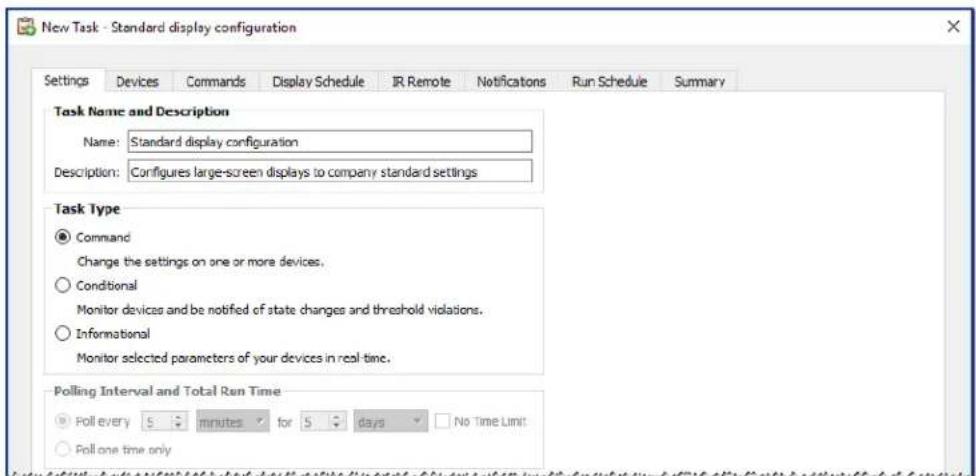
- Since the task will change the settings on displays, select Task Type: Command.
- On the Devices tab, select at least one already existing device of the same type. This way the Commands list will be populated with the correct controls for the device type.
- On the Commands tab, select and configure the values for each of the settings to be applied for the display configuration.
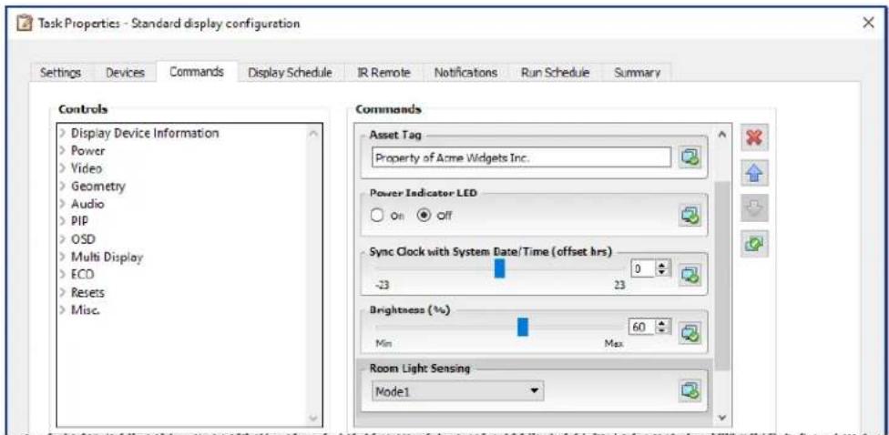
-
On the Run Schedule tab, select On Demand since the task will be run manually on new displays.
-
On the Summary tab, review the Task settings and then click OK.
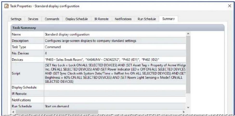
- There will now be a new task listed in the Inactive Tasks list that must be run manually.
- To run the task on new displays, first add them to the device tree, then modify the task by clicking the Properties icon. On the Devices tab, modify the selection to include the new displays to configure. Click OK and then run the task by clicking the Run button.
Example Task: Using Device Specific controls to configure a Tile Matrix
In this example a task is created to configure the Tile Matrix settings on 4 displays arranged in a 2 × 2 video wall. This task will allow all the displays in the video wall to be reconfigured using a single task. This is useful if, for example, a video wall is used in multiple configurations of Tile Matrix, and needs to be quickly reconfigured.
Some of the commands, such as enabling the Tile Matrix, are applied to all of the displays with the same settings. However, for setting the position of each display within the Tile Matrix, individual settings per display are required. This can be accomplished using the Device Selector controls.
- Create a new Task by clicking the New Task toolbar button, or selecting New Task... from the Tasks menu.
- Enter a Name and Description for the task to indicate the purpose of the task.
- Since the task will change the settings on displays, select Task Type: Command.
- On the Devices tab, select the 4 displays in the video wall.
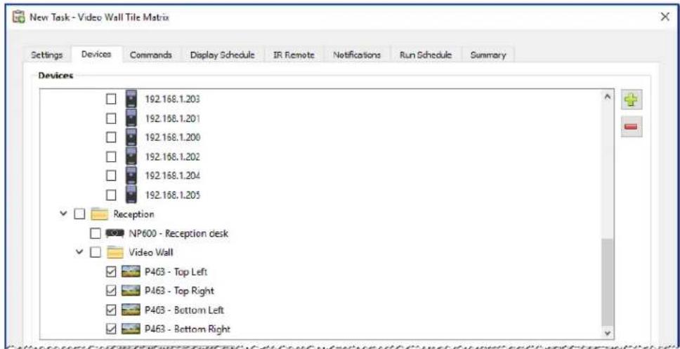
- On the Commands tab, select and add the controls to configure the H and V size of the Tile Matrix, as well as enabling the Tile Matrix. These controls will be applied with the same setting values for all of the displays. In this example the Tile Matrix # H Monitors and Tile Matrix # V Monitors are set to 2 since the video wall is arranged as a 2x2.
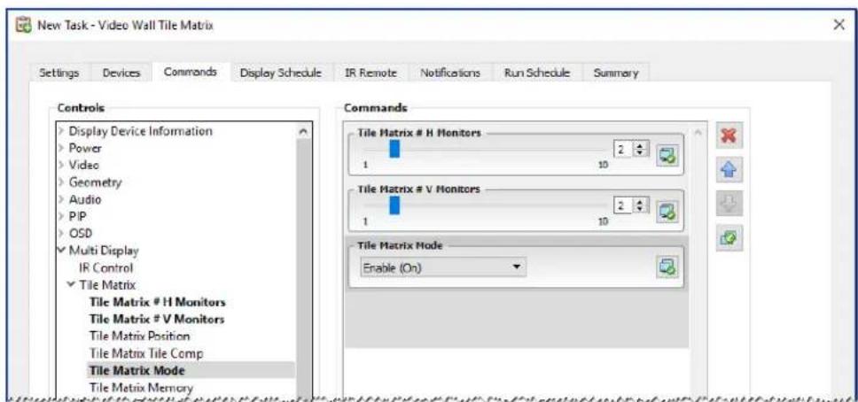
- Next, the position of each display within the Tile Matrix needs to be set using the Tile Matrix Position control. The value of this control setting needs to be different for each display in the Task. Select and add the setting and the following dialog will appear. Selecting Yes will automatically add one instance of the Tile Matrix Position control for each display, and sequentially assign the position setting value.
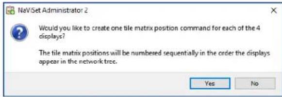

Note: Tile Matrix Positions are ordered left to right, top to bottom. So in this example, the top left display has position 1, the top right - position 2, bottom left - position 3, and bottom right - position 4. Ordering the displays in the device tree in this way allows the Tile Matrix Positions to be assigned automatically without the need to manually set them for each display.
- The Tile Matrix Position controls will show up in the command list as shown below.
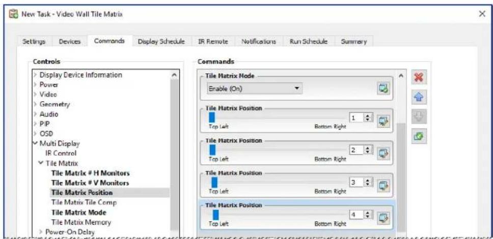
- The devices that a particular control will be applied to can be seen by mousing over the button as shown below.
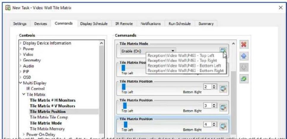
- If necessary, the devices that a control applies to can be modified by clicking on the button, which will open the Device Selector dialog. Select the devices that the control is to be applied to.
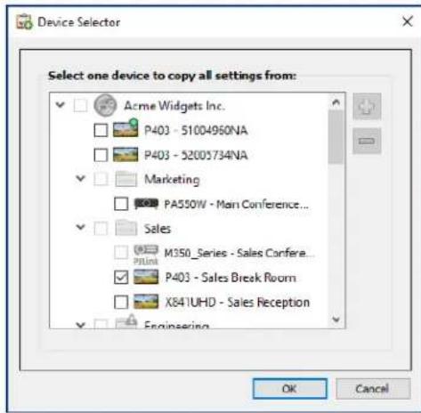
- Complete the task configuration and review the Task settings on the Summary tab.
- Click OK to add the new task listed in the Inactive Tasks list.
- Duplicate and modify the task as necessary to create other Tile Matrix configurations, such as Tile Matrix Off, etc.

Note: Depending on the changes being made to the Tile Matrix configuration of the displays, it may not be necessary for some of the commands to be performed with each task. For example, if the displays are being switched between a 2x2 tile matrix and individual displays (no tile matrix), then it is not necessary to send the Tile Matrix # H Monitors, Tile Matrix # V Monitors, and Tile Matrix Position settings for each task. In this particular case, once the displays have been initially configured, only the Tile Matrix Mode - Enable / Disable setting needs to be set to reconfigure the displays. This can make the Task operation faster by reducing unnecessary commands.
Example Task: Check computer conditions and reboot if necessary
In this example, a Task that uses Conditions and Actions is created to check to see if any computer devices are in a state that may require a restart, such as having very low available memory, or excessive CPU or GPU temperatures. The administrator will also be alerted via email whenever a computer is restarted as a result of this task.
- Create a new Task by clicking the New Task toolbar button, or selecting New Task... from the Tasks menu.
- Enter a Name and Description for the task to indicate the purpose of the task.
- Since the task will check the condition of a value, select the Task Type: Conditional.
- The task will check each device every 30 minutes, so set the Poll Every interval to 30 minutes. Since the task is meant to check the status of the computers and reboot if necessary, select No Time Limit so that the task will continuously run and check the devices.
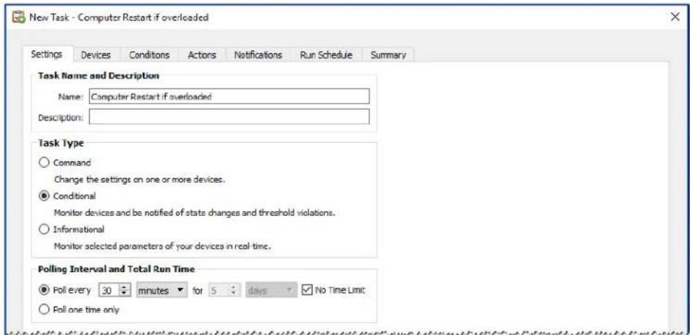
- On the Devices tab, select the devices to be checked.
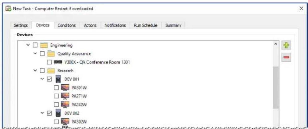
- On the Conditions tab, open the Computer Status section in the Controls list. Select controls to add them to the Conditions list, such as: Available Physical Memory, CPU Temp., and GPU Temp.. And then set the parameters for each of the conditions selected.
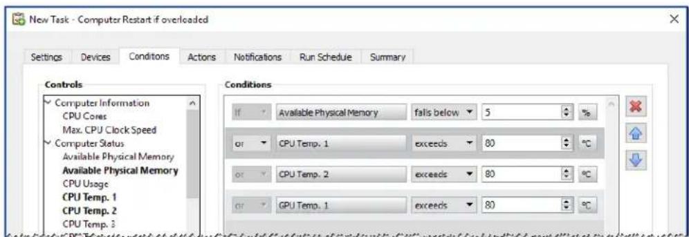
- On the Actions tab, select Computer Restart.
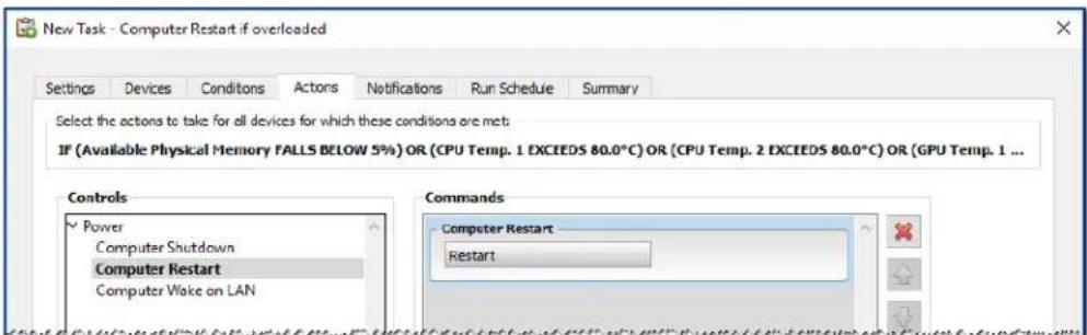
- On the Notifications tab, click Add a Notification..., enter the recipients email address and then click OK.
- Since the administrator will want to know immediately for each device if the condition is true, select Send all messages immediately as they occur. Since the administrator will want to be notified if a computer device is rebooted, select Alert Conditions in the Notify On... section.
- On the Run Schedule tab, select Start Options: Scheduled and then select the frequency at which the task will be performed. In this example, the task will run every day at 9 AM.
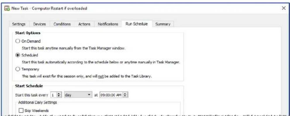
- On the Summary tab, review the Task settings and then click OK.
- There will now be a new task listed in the Inactive Tasks list that will automatically run on the selected days and times. The green background in the Next Start Time column indicates the task will run automatically at the time indicated.
Example Report: Query basic device information and export to Excel
In this example a report is created that will query basic information about all of the devices in the Device Tree. In order to avoid unnecessarily re-querying devices too often, a report that only queries devices if the information about them is older than two days. This will keep the information in the database up to date.
Once the report has completed, the results are exported to Excel so the data can be used and manipulated externally.
- Create a new Report by clicking the New Report toolbar button, or selecting New Report... from the Reports menu.
- Enter a Name and Description for the report to indicate the purpose of the report.
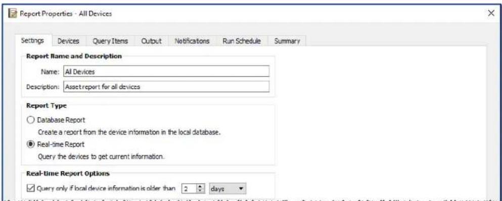
- Since the report will actually query devices, select Real-time Report as the Report Type. Select Query only if local device information is older than and select 2 days in order to avoid unnecessarily requerying devices and also keep the database up to date.
- On the Devices tab, select the devices to be included in the report.
Note: Windows computers and daisy chained large-screen displays are shown in the device tree in the Devices tab without any child devices (attached displays for Windows computers, and individual daisy chained large-screen displays for daisy chain hosts). These child devices will be determined when the Report operation is actually run, and automatically added to the report and the device tree.
- On the Query Items tab, select the desired items to query and include in the report.
- On the Output tab select the Output to file option, click Select... and choose a file type and name.
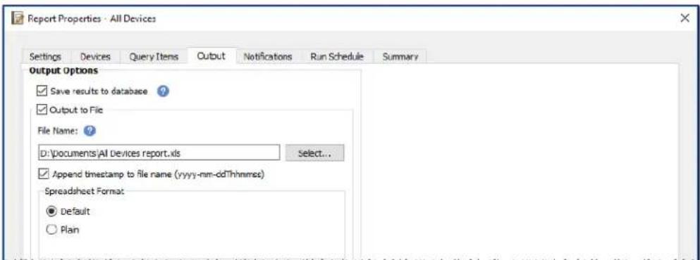
- On the Summary tab, review the Report settings and then click OK.
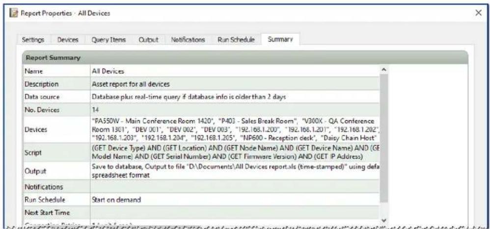
- There will now be a new report listed in the Inactive Reports list.
- Click the Run button to start the report. Once the report has completed querying all of the selected devices for which the database information is more than two days old, the spreadsheet will be automatically opened.
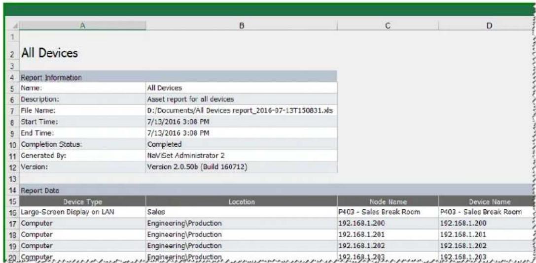

Frequently Asked Questions
Question: Can Task schedules be created with different start times for different days of the week? For example, to power on displays at different times on different days.
Answer: Yes. Simply create a Task with the desired Start Schedule times and days of the week to run. Then duplicate that task and edit it to change the start times and other days of the week. Repeat as necessary. So the end result is that there are multiple Tasks performing the same operation, but on different days and start times.
Question: Can two instances of the application share the same NaViSet Administrator database file simultaneously?
Answer: No. The database can only be opened by one instance at any one time.
Question: Can the database used by NaViSet Administrator be accessed by other software?
Answer: No. The database format is proprietary. Device information can be exported via delimited text files and Excel files.
Question: Can RS232 Splitters or Y adapters be used to connect multiple displays?
Answer: No. This will result in communication collisions and is an illegal topology for RS232 communications.
Question: What happens when there is a time change such as DST (Daylight saving time)?
Answer: Tasks that are currently inactive will automatically be rescheduled to take into account the new time from the host computer whenever it is changed. If tasks are running when the time change occurs, a message will be included in the task results indicating the time change.
Question: If the same brightness and color settings are applied to multiple displays will they look exactly the same?
Answer: For most display models, no. Since each display is different due to the age, usage, and normal tolerances, the same color setting values applied to different displays will result in some brightness and/or color differences.
Question: The results of a Task show numerous Last Query Still Running warning messages. What does this mean?
Answer: The task has not completed before the next time it is scheduled to poll has been reached. Increase the polling interval time to allow the task to complete on all of the devices specified.
Question: What happens to any scheduled tasks if NaViSet Administrator is closed? Do they need to be rescheduled?
Answer: NaViSet Administrator needs to be running in order for a scheduled task to start and run. If it is not running when a task is scheduled to start, then the task will be rescheduled for the next time period as soon as the application is run again. All tasks are automatically rescheduled whenever NaViSet Administrator is started and do not need to be manually rescheduled, however, tasks missed will not be caught up.
Question: How much network bandwidth does NaViSet Administrator use?
Answer: Communications to each device uses a minimal amount of network bandwidth - typically several kilobytes for most operations.
Question: How long would it take to perform an operation on a large number of devices?
Answer: NaViSet Administrator can communicate to multiple different devices in parallel, which speeds up operation by allowing simultaneous connections, and allows more operations to be performed while waiting for other devices to respond to commands. Up to 30 connections can be used by selecting Maximum simultaneous network connections in the application Preferences (see page 116).
Assuming that all 30 connections are used with the maximum possible efficiency, then operations on all devices will complete at 30 times the speed of performing the operation on all devices in serial using one connection. Depending on the device, connection type, and operation being performed, operation times are typically between 5 seconds to 1 minute.
Example: Approximately how long would it take to power off 1000 displays?
Assuming a power off operation takes 15 seconds to perform on a device, if performed serially using one connection the total time would be about 15 seconds × 1000 = 15000 seconds (over 4 hours). If 30 connections are used, then the time is 15 × 1000 ÷ 30 = 500 seconds (just over 8 minutes). It is assumed that no other operations are being performed at the same time.
Question: Is it possible to connect to a display that is connected via RS232 to the local computer?
Answer: Yes. Install and configure the LAN to RS232 Bridge application on the local computer. Add the display to the device tree in the same way as any other device, but use either the computer's actual IP address, network name, or the IP address 127.0.0.1.
Question: Which port needs to be opened on the network to allow access to the device?
Answer:
- NEC large-screen displays - port 7142
- NEC projectors - port 7142
- PJLink devices - port 7352
- Via WMI to Desktop displays, NEC large-screen displays, Windows computers - WMI normally uses random ports after initial connection on port 135. Refer to Microsoft documentation for further information.

Troubleshooting
Problem: Unable to connect to a Windows Computer via WMI
Windows Computers Only
If an error occurred when performing any Test operation, follow these troubleshooting steps:
- Confirm that the remote computer is powered on and fully booted.
- Confirm that the computer name or IP address is correct.
- Confirm that the user credentials entered are correct for an administrative user on the computer or domain administrator.
- Confirm that the Windows Firewall is not blocking access to WMI. See page 46 for more details.
If the Windows computers on the network are part of a Windows Workgroup and not a Domain, the default UAC (User Account Control) security settings will not allow access to WMI, even if the Firewall is disabled.
Problem: Unable to communicate with an NEC large-screen display
If an error occurred when performing any Test operation, follow these troubleshooting steps:
- Confirm that the display is a supported model and is powered on.
- Confirm the IP address of the display is correct. If using the LAN to RS232 Bridge make sure the IP address or host name of the Windows computer is correct.
- Confirm that the Monitor ID being used to connect to a display matches the Monitor ID set on the OSD.
- If using the LAN to RS232 Bridge utility, confirm that it is configured correctly and has been started. Confirm that the Windows Firewall has been opened correctly for the Network Location Type being used. See "Troubleshooting the LAN to RS232 Bridge" on page 149.
- Confirm that the first display is correctly configured to use RS232 or LAN, depending on the connection type. See the configuration information starting on page 51 for details.
- For displays daisy chained via RS232, confirm that displays connected to the first display are configured to use RS232 and have unique Monitor IDs.
- For displays daisy chained via RS232, confirm that displays are connected using crossover / NULL modem type RS232 cables, and are connected to the correct IN and OUT sockets on the displays.
- For displays daisy chained via LAN, confirm that the network connection to the first display is connected to the LAN 1 input. The LAN 2 output should connect to the LAN 1 input on the next display in the daisy chain.
If the display is connected directly to LAN (not using the LAN to RS232 Bridge), try connecting to the display's internal web host using a web browser and enter the IP address of the display to verify connectivity via HTTP.
Try resetting the LAN settings on the display and reconfiguring. Power Off and On the display.
Problem: Unable to communicate with an NEC projector
If an error occurred when performing any Test operation, follow these troubleshooting steps:
- Confirm the IP address of the projector, or IP address or Windows computer name of the Windows computer (if using the LAN to RS232 Bridge) is correct.
If using the LAN to RS232 Bridge utility, confirm that it is configured correctly and has been started. See "Troubleshooting the LAN to RS232 Bridge" on page 149.
If the projector is connected directly to LAN (not using the LAN to RS232 Bridge), try connecting to the projector's internal web host using a web browser and enter the IP address of the projector to verify connectivity via HTTP. - Some projector models require the communications setting to be manually configured between RS232 and LAN via the On Screen Display. Select the appropriate setting for the connection being used.
Appendix

Comparison of connection methods for NEC large-screen displays
| Connection Method | ||||
| Direct LAN LAN | to RS232 Bridge | RS232 WMI Provider' | DDC/CI WMI Provider' | |
| Host Windows Computer Required | No Yes Yes Yes | |||
| Operation Speed Fastest | Fastest Slowest Average | |||
| RS232 Daisy Chain Supported | Yes Yes Yes | No (multi-monitor on computer is supported) | ||
| Control when remote host computer is powered down or not functional | N/A No No No | |||
| Control without user logged in to remote host computer | N/A No Yes Yes | |||
| Use and select any video input | Yes Yes Yes | No (Current input only. Must be VGA or DVI.) | ||
| Configuration of Monitor IDs and number of displays on host computer | N/A | No configuration necessary | Must be specifically configured on the host computer | No configuration necessary |
| Maximum cable length | 100m 10m 10m | 3m | ||
| Additional limitations | One COM port supported | Multiple COM ports supported | No splitters, KVMs, or Video over CAT5/6. Two-way communications using DisplayPort or HDMI inputs is not supported. | |
| Supported on SBC (Single Board Computer) | N/A Yes Yes | No | ||
| IP Address | IP address required for display | Shares IP address of host computer | Shares IP address of host computer | Shares IP address of host computer |
| Network Security | None | None | Yes. Requires administrator credentials. | Yes. Requires administrator credentials. |
| Typical Standard Refresh Time | 20 seconds per display | 20 seconds per display | 20 seconds per display + 10 seconds x the total number of displays | 30 seconds |
| Typical Full Refresh Time | 120 seconds per display | 120 seconds per display | 60 seconds per display + 10 seconds x the total number of displays | 75 seconds |
| See connection diagram on | page 51 page 53 | page 57 | page 45 | |
1 Accessible from Windows version only
Daisy Chain RS232 vs. Individual LAN Connections
The following table compares connecting large-screen displays individually via LAN vs. using an RS232 daisy chain between displays:
| Connection Method | ||
| Daisy Chain RS232 Individual | LAN Connection | |
| Operation Speed | Slower. Limited to one operation on one display on the daisy chain at a time. | Faster. Simultaneous (parallel) operations to each display (up to maximum limit set in the application Preferences). |
| IP Addresses One IP address required for all displays. One IP address for each display. | ||
| Connectivity | Single RS232 cables daisy chained between displays. | Individual LAN cable runs from each display to a hub/switch/outer. |
| Robustness | Failure or removal of one display or cable will disrupt communications to all others further along the daisy chain. | Failure of a display or cable will not impact communications to other displays. |

Wake-on-LAN (WoL) Configuration
In order to wake up a remote Windows computer using the Wol protocol, the computer must be configured to enable the Wol functionality.
On most computers WoL needs to be enabled in both the BIOS (Basic Input/Output System) settings and in Windows. Consult the computer's documentation for information on how to access and enable the BIOS WoL settings if applicable.
In Windows, the Wol functionality is integrated into the Device Manager, and is available in the Power Management tab of each network device.
When performing a Wake On LAN operation in NaViSet Administrator, a magic packet will be broadcast on the network interface selected in the Preferences to the MAC address of the computer. The magic packet is sent as a UDP datagram on port 9. Be sure that firewalls and routers do not filter or block this.

Note: In most cases Wol will not work outside the local network or current network subnet due to the broadcast nature of the protocol and configuration of most routers.
Examples of network adapter Wake on LAN / Wake On Magic Packet settings:
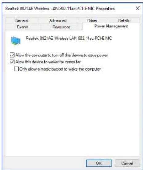
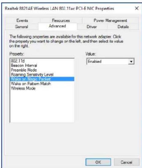
Using Open Hardware Monitor
NaViSet Administrator can interface with the free open-source hardware monitoring Open Hardware Monitor application in order to provide extended monitoring of a remote Windows computer's hardware status, such as temperatures and fan speeds. These extra parameters on the status of a remote computer can be useful in checking for abnormal conditions such as overheating, or cooling fan failures which could lead to a failure or mis-operation of the computer.

Note: Since NaViSet Administrator operates by polling devices, and not by remote devices automatically signaling of an abnormal condition, a Task must be used to periodically query the remote devices being monitored and check for an abnormal condition.
Installing and Configuring Open Hardware Monitor
To use Open Hardware Monitor with NaViSet Administrator.
- On the remote Windows computer that is to be monitored, install the Open Hardware Monitor application available from http://openhardwaremonitor.org.
- Start the Open Hardware Monitor application.
- In the Options menu, configure the application to Run On Windows Startup and, if desired, to Start Minimized.
- Confirm that the desired parameters are being monitored and reported within the application.
- Leave the application running.
- In NaViSet Administrator, select the remote Windows computer in the Device Tree and open the device's tab by double clicking the device.
- On the device's Info tab click either Standard Refresh or Full Refresh to refresh the status information from the remote computer.
- The supported parameters from Open Hardware Monitor will appear in the Computer Status Information table.

Note: NEC is unable to provide support or assistance with Open Hardware Monitor, and is not responsible for its operation, development, functionality, or availability.
Supported Sensors
NaViSet Administrator supports reading CPU, GPU, and Main Board temperatures and fan speeds from Open Hardware Monitor. Since Open Hardware Monitor supports monitoring of a broad range of sensor types within the computer, devices are grouped into the following categories:
CPU Temperatures 1 thru 8 in ^ C
CPU Fan Speeds 1 thru 8 in RPM
Main Board Temperatures 1 thru 8 in ^ C
Main Board Fan Speeds 1 thru 8 in RPM
GPU Temperatures 1 thru 8 in ^ C
GPU Fan Speeds 1 thru 8 in RPM
Using in Tasks and Reports
The sensor values from Open Hardware Monitor can be used in Tasks and Reports in NaViSet Administrator. For example, a Task can be created to issue an alert if a fan speed drops below a certain RPM, or if a temperature exceeds a certain value.
When a computer is selected as a device in a Conditional type Task, the list of Controls in the conditions will contain a section called Computer Status, which contains all of the sensor categories that can be used from Open Hardware Monitor.
In the following example the CPU Temperature 1 sensor is used to create an alert if the value exceeds 50^ , or if the CPU 1 fan speed falls below 500 rpm.
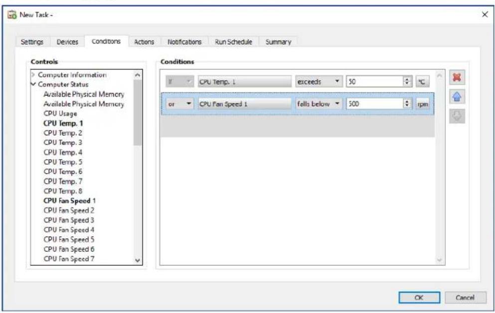

LAN to RS232 Bridge Configuration
About
The LAN to RS232 Bridge is a utility that allows remote access via LAN to NEC large-screen displays or projectors that are connected to a remote Windows computer via an RS232 connection. This essentially makes the Windows computer appear to be the LAN connection of a large-screen display or projector. It is bridging communications between LAN and the RS232 port to the display. Applications like NaViSet Administrator can then access displays by connecting to the IP address of the Windows computer, and sending requests just as if the display was connected via a built-in LAN connection.
This allows a host computer to effectively share its LAN connection with the display, allowing remote access to the display via LAN, but while only using one LAN connection.
This is useful for:
Large-screen display and projector models that have an RS232 connection, but no built-in LAN connection.
- Situations where it is not possible or desirable to use two LAN connections and IP addresses (one for the host computer and one for the display).
- Allows access to devices through Windows computers from both Windows and Mac versions of NaViSet Administrator.
See pages 53, 55, and 64 of the Configuring Devices chapter for complete information on connecting and configuring devices for use with the LAN to RS232 Bridge.
Operation
The utility runs in the Windows System Tray and waits for incoming requests via LAN. When a request is received, it is then forwarded on to the selected RS232 COM port to the display. Replies from the display(s) are then sent back over LAN.
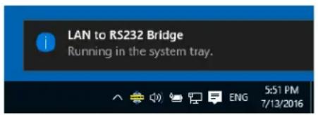

Note: Windows may hide the system tray icon by default. Click the Show Hidden Icons button in the system tray to configure which icons are shown on the system tray.
Limitations
There are several important limitations to using this utility:
-
The application runs in the Windows System Tray, and only loads when a user has logged into the computer. Therefore, connectivity to the display will not be available until a user has logged in.
-
Since the application settings are stored on a per-user basis, be sure to configure the settings while logged in as the user that will be normally logged into the computer.
Communications will not be possible while the host computer is in power off, sleep, or hibernate modes.
Only one COM port can be used. If multiple large-screen displays are to be connected, they must be daisy chained from the RS232 OUT on the first display connected to the computer. - Only one simultaneous remote connection is allowed. If a connection request is received while another connection is already in use, it will be refused.
- The host computer must allow TCP LAN traffic on port 7142. Firewalls must be configured to allow unfiltered traffic on this port. The installer will automatically open this port on the Windows firewall.
Configuring the LAN to RS232 Bridge
- Install the LAN to RS232 Bridge from the NaViSet Administrator 2 installer packages.
- Run the LAN to RS232 Bridge application which can be found in the Start Programs NEC Display Solutions LAN to RS232 Bridge menu.
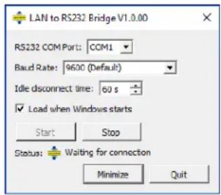
- Select the RS232 COM Port that the display is connected to from the list.
- Select the correct Baud Rate for the connected display. All NEC large-screen displays use 9600 baud. Projectors can use 9600, 19200, or 38400 baud. Be sure the baud rate selected matches the baud rate configured in the projector's On Screen Display.
- To automatically load the LAN to RS232 Bridge application when Windows starts, select Load when Windows starts. If this is not selected, it must be manually started each time Windows starts.
- Click Start to start the bridge operation. It will listen for incoming connections on LAN. When a connection is received, the Status: indicator will change from Waiting for connection.
- When finished configuring the settings, click the Minimize button to close the window and keep the application running in the system tray.
- Clicking Quit will close the application and it will no longer accept incoming connections.
Troubleshooting the LAN to RS232 Bridge
Follow these troubleshooting steps if problems are encountered with connecting to the LAN to RS232 Bridge utility:
- Test the connection and configuration by connecting from another computer using the IP address of the computer running the LAN to RS232 Bridge utility.
- Check that the utility has been started.
- Watch the Status: in the configuration window. It will show if a remote connection has been attempted. If no remote connection is made, check the firewall settings. The application is listed in the Windows Firewall as
LAN to RS232 Bridge Application. Make sure it has permissions on the Network Location Type being used for the remote network connection. Network Location Types are typically Home/Work (Private) and Public.
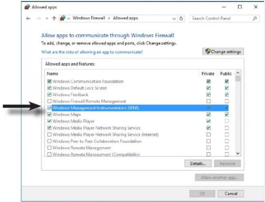
Large-screen displays only: Check that the display has been configured to use the RS232 connection and not LAN.
Large-screen displays only: Check that the Monitor ID is set correctly on the display.
Large-screen displays only: Check that the RS232 cable is connected to the RS-232C INPUT on the display.
Make sure the selected Baud Rate is selected is correct for the display type and model being used.
- Check that the RS232 cable to the display is a crossover cable type and is connected to the RS232 input on the display.
- Check that another application isn't using the COM port.

RS232 WMI Provider Configuration
About
The RS232 WMI Provider is installed on remote Windows computers that have compatible NEC large-screen displays with an RS232 communications (COM) port. It will receive queries and commands from the NaViSet Administrator application via WMI, and communicate these commands to the display via RS232^ . The WMI Provider is a supplier, or provider, of the monitor metadata information to the NaViSet Administrator application. It is a completely background process that gets loaded temporarily whenever a request or command is received and, therefore, has no interaction with the users on the remote computers.

Note: There are several different methods of accessing NEC large-screen displays remotely. Please see Appendix A on page 143 which provides a comparison of the different types, their benefits and drawbacks. Using the RS232 WMI Provider with a large number of displays connected can result in slow operation, since connectivity with each display must be confirmed before a command can be performed, and is therefore not recommended.
Configuring
Unlike the LAN to RS232 Bridge utility, the RS232 WMI Provider must be locally configured with the number of displays connected, the Monitor IDs for each display, and the RS232 COM port(s) on the host computer to use.
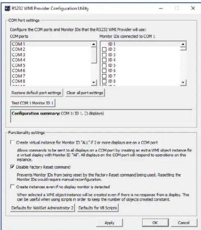
A utility application called RS232 WMI Provider Configuration Utility is installed with the RS232 WMI Provider to allow these configurations to easily be made. This is accessed from the Start Programs NEC Display Solutions RS232 WMI Provider menu.
The configuration utility is used to make the following configuration settings used by the WMI Provider:
- Configuring the RS232 COM ports used to communicate with the NEC display(s).
- Configuring the Monitor IDs to use with each display (which must match the settings on each display)
- Testing the communications with each display.
- Configuring various advanced settings that impact the behavior of the WMI Provider.
Follow these steps to plan and configure the settings for use with NaViSet Administrator.
- Identify the COM port numbers on the host computer that will be used to communicate with the display(s).
- Connect the display(s) to the host computer using RS232 crossover cables. Be sure to correctly identify the RS232 IN and OUT connections on the display. The computer will connect to the RS232 IN on the display.
- Configure the Monitor IDs for each display using the On Screen Display on each. If multiple displays are being used with an RS232 daisy chain connection, then each display on the chain must have a unique Monitor ID.
- In the configuration utility application, click the Clear All Port Settings button to reset any previous configurations.
- Select the COM port being used on the host computer in the list.
- Next, select the Monitor ID for the first display and make sure it is checked.
- Click the Test COM n Monitor ID x button to test the communications with the display (where n and x are the COM port number and Monitor ID). If the communications is successful, the model name and serial number of the display will be shown. See "Troubleshooting" on page 141 if the display is not detected.
- Repeat steps 5 thru 7 for all remaining displays.
- Verify the configuration settings in the Configuration Summary section.
- If the WMI Provider is being used with the NaViSet Administrator 2 application, make sure the Defaults for NaViSet Administrator 2 is selected.
- Click Apply or OK to close.
- The RS232 WMI Provider is now ready for access by remote. Try connecting by adding the computer as a Windows computer on LAN (WMI) in the NaViSet Administrator application.
Advanced Settings
The RS232 WMI Provider has several advanced settings for use in certain configurations and scenarios.
Create virtual instance for Monitor ID "All" if two or more displays are on a COM port
This setting allows commands to be simultaneously sent to all displays on a particular COM port, by creating an extra WMI object instance for a virtual display with Monitor ID "All". All the displays on the COM port will respond to operations on this instance.

Note: This setting is intended for use with WMI scripts, and not the NaViSet Administrator 2 application. It should not be selected when using the NaViSet Administrator 2 application.
Disable Factory Reset Command
This setting prevents the Monitor IDs assigned to each display from being reset by the Factory Reset command being used. Resetting the Monitor IDs would require that each display be manually re-configured via the On Screen Display.
Create instances even if no display monitor is detected
When this setting is selected, a WMI object instance will be created for each display configured in the WMI provider, even if there is no response from a display. This can be useful when using WMI scripts, because it keeps the total number and sequence of the WMI objects created constant.

Note: This setting is intended for use with WMI scripts, and not the NaViSet Administrator 2 application. It should not be selected when using the NaViSet Administrator 2 application.
Appendix

Windows Management Instrumentation
About WMI
Windows Management Instrumentation (WMI) provides fully integrated operating system support for system and applications management on a Windows computer. WMI provides a model of the configuration, status, and operational aspects of Windows operating systems, assisting management applications in creating solutions that reduce the maintenance and life cycle costs of managing Windows and hardware devices.
NaViSet Administrator is able to access a remote computer and read this information using WMI.
Without installing any additional software on a remote computer, NaViSet Administrator is able to report about many different items such as:
Make, model, serial number, and resolution of any connected display monitor(s)
Make, model, and serial number of the computer (if available)
CPU type, speed, and current usage
- Operating system version and service pack
- System memory size and current usage
NaViSet Administrator is able to enhance the amount of information available on the connected display monitors on a remote computer by installing a custom WMI Provider.
NaViSet Administrator WMI Providers
Two different WMI Providers are included with NaViSet Administrator, the RS232 WMI Provider (used for large-screen displays connected to the computer via RS232), and the DDC/CI WMI Provider (used for desktop displays and communicates using the video cable to the display).
Note: The RS232 and DDC/CI WMI Providers cannot both be installed at the same time on a computer.
The NaViSet Administrator WMI Providers should be installed on all remote computers that have compatible NEC display monitors. The WMI Provider receives queries and commands from the NaViSet Administrator application, via WMI, and communicates these commands to the display via DDC/CI or RS232. The WMI Provider is a supplier or provider of the monitor metadata to the NaViSet Administrator application. It is a completely background process that gets loaded temporarily whenever a request or command is received and has no direct interaction with the users on the remote computers.
In order to perform adjustments and advanced query functions, it is necessary to install one of the NaViSet Administrator WMI Provider on each remote Windows computer. If the WMI Provider is not installed, then NaViSet Administrator can still gather basic information about the main display connected to the computer by using standard built-in WMI classes. This information is limited to static metadata and so no adjustment of the display is possible. This basic information is available regardless of the model or make of display connected.
The NEC WMI Providers create a standard WMI Object that can be accessed not only from the NaViSet Administrator application, but also 3rd party asset management applications and also several other WMI interfaces such as VB Scripts.
Appendix

WMI VB Scripts
The DDC/CI and RS232 WMI Providers included with NaViSet Administrator allow connected NEC desktop and large-screen displays to be accessed and controlled using 3rd party asset management applications, and also via simple VB Scripts. This makes it very easy to perform custom operations if necessary, without the need to use the NaViSet Administrator application.
VB Scripts can be written to access the WMI Properties and Methods of the NaViSet Administrator WMI Providers. The WMI provider is a class called Win32_AdvancedDesktopMonitor, and exists in the Root\CIMV2 namespace.
The various Properties and Methods available can be easily explored using either the Windows built-in WMI Tester application (WbemTest.exe), or the WMI CIM Studio and WMI Object Browser available in the Microsoft WMI SDK, or various 3rd party WMI tools.
Once the names and parameters of the desired Properties and Methods of the WMI Provider are known, they can then be accessed via a VB Script file.
VB Scripts are text files with a .vbs extension and can be run either from the command line using cscript.exe, or via the Windows GUI which runs wscript.exe.
Details of generating VB Scripts are beyond the scope of this manual. However, several sample VB Script files are provided for reference on the NaViSet Administrator install media.
Sample VB Script files included:
MonitorPowerOn.vbs
Demonstrates how to control the monitor power by turning the monitor on.
MonitorPowerOff.vbs
Demonstrates how to control the monitor power by turning the monitor off.
MonitorInfo.vbs
Demonstrates how to read the WMI Properties to query and display some of the basic monitor metadata such as model number, serial number, date of manufacture, etc. Most of this functionality is only available for displays when using the DDC/CI WMI Provider.
ResetColor.vbs
Demonstrates how to perform an action by calling a WMI Method. This will reset the monitor color settings.
ReadBrightContrast.vbs
Demonstrates how to perform an action by calling a WMI Method. This will read the values of the Brightness and Contrast controls and display them as a percentage value.
SetMonitorBrightness.vbs
Demonstrates how to perform an action by calling a WMI Method. This will set the display Brightness control to a percentage value. It will also display the Brightness control percentage value before and after the adjustment.
IRRemote.vbs
Demonstrates how to perform an action by calling a WMI Method. This will send a series of IR Remote commands to the display mimicking the IR Remote control (if available). The file should be edited to set the desired IR Remote commands. This functionality is only available on NEC large-screen displays connected via RS232.
ReadInternalTempSensors.vbs
Demonstrates how to read the internal temperature sensors in supported displays.
Glossary
DDC/CI (Display Data Channel / Command Interface) - A two-way communications link between the video graphics adapter and display monitor using the standard video signal cable.
EDID (Extended Display Identification Data) - A data structure provided by a display to describe its capabilities to a video source.
OPS (Open Pluggable Specification) - A standardized slot design for digital signage devices and pluggable media players.
OSD (On Screen Display) - Display controls and status information superimposed on the screen image.
RS232 - A series of standards for serial binary single-ended data and control signals connecting between DTE (data terminal equipment) and DCE (data circuit-terminating equipment).
SBC (Single Board Computer) - A complete computer built on a single circuit board, with microprocessor, memory, and other features.
SMTP (Simple Mail Transfer Protocol) - An Internet standard for electronic mail (email) transmission across Internet.
SSL/TLS (Secure Sockets Layer / Transport Layer Security) - A protocol for encrypting information over the Internet.
USB (Universal Serial Bus) - A communication bus used to connect up to 127 devices such as keyboards, mice, scanners, color sensors, etc.
VESA (Video Electronics Standards Association) - An international non-profit corporation that supports and sets industry-wide interface standards for the PC, workstation, and consumer electronics industries.
WMI (Windows Management Instrumentation) - A set of extensions to the Windows Driver Model that provides an operating system interface through which instrumented components provide information and notification.
NEC
Copyright © 2023 Sharp NEC Display Solutions, Ltd. All rights reserved.
USA and Canada: www.sharpnecdisplays.us
Europe: www.sharpnecdisplays.eu
Asia Pacific: www. sharp-nec-displays.com/ap

NaViSet Administrator 2
PJLink trademark and logo are trademarks applied for registration or are already registered in Japan, the United States of America and other countries and areas.
Copyright © 2023 Sharp NEC Display Solutions, Ltd.
NaViSet Administrator understands the following types of network operators:
Create instances even if no display monitor is detected
NaViSet Administrator-WMI Provider
SetMonitorBrightness.vbs
NaViSet Administrator 2
PJLink trademark and logo are trademarks applied for registration or are already registered in Japan, the United States of America and other countries and areas.
Copyright © 2023 Sharp NEC Display Solutions, Ltd.
Application NaViSet Administrator

If an error occurred when performing any Test operation, follow these troubleshooting steps:
Configuration Wake-on-LAN (WoL)
Configuration de LAN to RS232 Bridge
A propos
Configuration de LAN to RS232 Bridge
SetMonitorBrightness.vbs
Europe: www.sharpnecdisplays.eu

NaViSet Administrator 2
Copyright © 2023 Sharp NEC Display Solutions, Ltd.
Ventana principal 15
SetMonitorBrightness.vbs
NaViSet Administrator 2
Copyright © 2023 Sharp NEC Display Solutions, Ltd.
All rights reserved. 有
八P3K12K12K12K12K12K12K12K12K12K12K12K12K12K12K12K12K12K12K12K12K12K12K12K12K12K12K12K12K12K12K12K12K12K12 K12 K12 K12 K12 K12 K12 K12 K12 K12 K12 K12 K12 K12 K12 K12 K12 K12 K12 K12 K12 K12 K12 K12 K12 K12 K12 K12 K12 K12 K12 K12 K12 K12 K
NaViSet Administrator
刀一

Duckwinds to the任意的場所移動成的、柔軟性高、Dusts of the space is the largest with the use of the most effective and efficient use of the most effective.
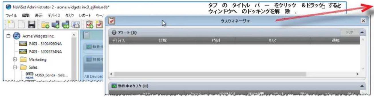
DssKngsEeTOWndUH=、夕PUS上n的xPouanf、DcWINDUo的TtUlB-上nXpOtanuokL 0
Doppiengataedwindw和口一tenndw是也,表示M二一加表示·非表示选折成
デバイスのプロバチウインドウ
Configuration Features
Proof of Play is Proof of Play's Tusk's Pro10kaiyaiao 4oogd afo 60.
NaViSet Administrator WMI Provider
SetMonitorBrightness.vbs
Copyright © 2023 Sharp NEC Display Solutions, Ltd. All rights reserved.
日本:www.sharp-nec-displays.com/jp

NaViSet Administrator 2
用户指南
简体中文
软件更新
PJLink trademark and logo are trademarks applied for registration or are already registered in Japan, the United States of America and other countries and areas.
Copyright © 2023 Sharp NEC Display Solutions, Ltd.
NaViSet Administrator 简介
简介
"Active Directory 查询”对话框
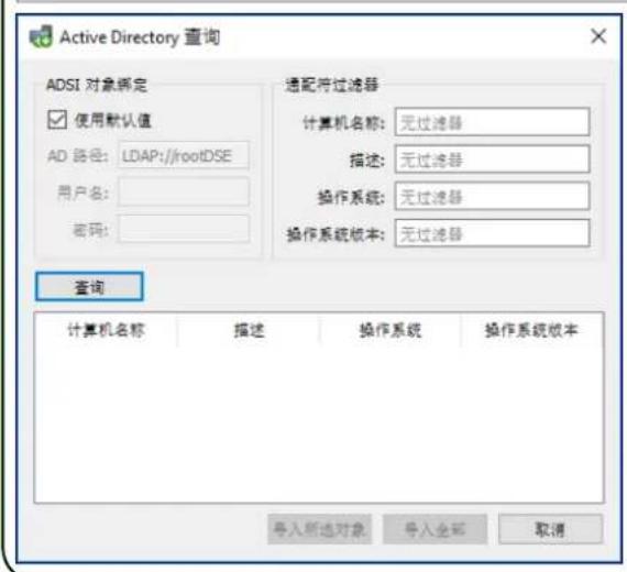
LAN to RS232 Bridge 配置
关于
配置 LAN to RS232 Bridge
LAN to RS232 Bridge 故障排除
NaViSet Administrator WMI Providers
SetMonitorBrightness.vbs
Copyright © 2023 Sharp NEC Display Solutions, Ltd. All rights reserved.
中国:cn.nec.com

NaViSet Administrator 2
사용자 가이드 한국어
SófrénteWeyerJenldeaiTe
KanhtyroNn.
将吉用贝
Apple, Macintosh, Numbers, Mac, macOS & Mac Roog is meKf f tA Ks a e T r i Apple Inc.
I
Copyright © 2023 Sharp NEC Display Solutions, Ltd.
i
本国的国利保有,自的承用在国内。
MUKJ ENB 17P, MUKJ TAKKENBEH HONGHONG HONGHONG HONGHONG HONGHONG HONGHONG HONGHONG HONGHONG HONGHONG HONGHONG HONGHONG HONGHONG HONGHONG HONGHONG HONGHONG HONGHONG HONGHONG HONGHONG HONGHONG HONGHONG HONGHONG HONGHONG HONGHONG HONGHONG HONGHONG HONGHONG HONGHON
的内用是,
MUKGJHJ111111111111111111111111111111111111111
http://www. sharpnecdisplays.us/navisetadministrator
中国:www. sharp-nec- displays.com/ap
目录
| SWIFT | |
| 수의 사형 | .6 |
| 지원 기재 | .7 |
| 지스본 majority사형 | .8 |
| SWIFT Administrative Stange 9 | |
| SWIFT Administrative Stange 1 NaViSet Administrator Stange 9 | |
| SWIFT Administrative Stange 2 | .9 |
| SWIFT Administrative Stange 3 | .10 |
| SWIFT Administrative Stange 4 | .12 |
| SWIFT Administrative Stange 5 | .13 |
| SWIFT Administrative Stange 6 | .14 |
| SWIFT Administrative Stange 7 | .15 |
| SWIFT Administrative Stange 8 | .15 |
| SWIFT Administrative Stange 9 | .16 |
| SWIFT Administrative Stange 10 | .21 |
| SWIFT Administrative Stange 11 | .21 |
| SWIFT Administrative Stange 12 | .21 |
| SWIFT Administrative Stange 13 | .21 |
| SWIFT Administrative Stange 14 | .22 |
| SWIFT Administrative Stange 15 | |
| SWIFT Administrative Stange 16 | |
| SWIFT Administrative Stange 17 | |
| SWIFT Administrative Stange 18 | |
| SWIFT Administrative Stange 19 | |
| SWIFT Administrative Stange 20 | |
| SWIFT Administrative Stange 21 | |
| SWIFT Administrative Stange 22 | |
| SWIFT Administrative Stange 23 | |
| SWIFT Administrative Stange 24 | |
| SWIFT Administrative Stange 25 | |
| SWIFT Administrative Stange 26 | |
| SWIFT Administrative Stange 27 | |
| SWIFT Administrative Stange 28 | |
| SWIFT Administrative Stange 29 | |
| SWIFT Administrative Stange 30 | |
| SWIFT Administrative Stange 31 | |
| SWIFT Administrative Stange 32 | |
| SWIFT Administrative Stange 33 | |
| SWIFT Administrative Stange 34 | |
| SWIFT Administrative Stange 35 | |
| SWIFT Administrative Stange 36 | |
| SWIFT Administrative Stange 37 | |
| SWIFT Administrative Stange 38 | |
| SWIFT Administrative Stange 39 | |
| SWIFT Administrative Stange 40 | |
| SWIFT Administrative Stange 41 | |
| SWIFT Administrative Stange 42 | |
| SWIFT Administrative Stange 43 | |
| SWIFT Administrative Stange 44 | |
| SWIFT Administrative Stange 45 | |
| SWIFT Administrative Stange 46 | |
| SWIFT Administrative Stange 47 | |
| SWIFT Administrative Stange 48 | |
| SWIFT Administrative Stange 49 | |
| SWIFT Administrative Stange 50 | |
| SWIFT Administrative Stange 51 | |
| SWIFT Administrative Stange 52 | |
| SWIFT Administrative Stange 53 | |
| SWIFT Administrative Stange 54 | |
| SWIFT Administrative Stange 55 | |
| SWIFT Administrative Stange 56 | |
| SWIFT Administrative Stange 57 | |
| SWIFT Administrative Stange 58 | |
| SWIFT Administrative Stange 59 | |
| SWIFT Administrative Stange 60 | |
| SWIFT Administrative Stange 61 | |
| SWIFT Administrative Stange 62 | |
| SWIFT Administrative Stange 63 | |
Windows 装載器を通過 LAN に実装いたします NEC 执業機器................................................................................................
65
| Cameroon 5 壁挂 302 | |
| Cameroon 6 | 肖绩 7 壁挂 100 |
| Cameroon 7 | 肖绩 8 壁挂 100 |
| Cameroon 8 | 肖绩 9 壁挂 100 |
| Cameroon 9 | 肖绩 10 壁挂 100 |
| Cameroon 10 | 肖绩 11 壁挂 100 |
| Cameroon 11 | 肖绩 12 壁挂 100 |
| Cameroon 12 | 肖绩 13 壁挂 100 |
| Cameroon 14 | 肖绩 15 壁挂 100 |
| Cameroon 15 | 肖绩 16 壁挂 100 |
| Cameroon 16 | 肖绩 17 壁挂 100 |
| Cameroon 17 | 肖绩 18 壁挂 100 |
| Cameroon 18 | 肖绩 19 壁挂 100 |
| Cameroon 19 | 肖绩 20 壁挂 100 |
| Cameroon 20 | 肖绩 21 壁挂 100 |
| Cameroon 21 | 肖绩 22 壁挂 100 |
| Cameroon 22 | 肖绩 23 壁挂 100 |
| Cameroon 23 | 肖绩 24 壁挂 100 |
| Cameroon 24 | 肖绩 25 壁挂 100 |
| Cameroon 25 | 肖绩 26 壁挂 100 |
| Cameroon 26 | 肖绩 27 壁挂 100 |
| Cameroon 27 | 肖绩 28 壁挂 100 |
| Cameroon 28 | 肖绩 29 壁挂 100 |
| Cameroon 29 | 肖绩 30 壁挂 100 |
| Cameroon 30 | 肖绩 31 壁挂 100 |
| Cameroon 31 | 肖绩 32 壁挂 100 |
| Cameroon 32 | 肖绩 33 壁挂 100 |
| Cameroon 33 | 肖绩 34 壁挂 100 |
| Cameroon 34 | 肖绩 35 壁挂 100 |
| Cameroon 35 | 肖绩 36 壁挂 100 |
| Cameroon 36 | 肖绩 37 壁挂 100 |
| Cameroon 37 | 肖绩 38 壁挂 100 |
| Cameroon 38 | 肖绩 39 壁挂 100 |
| Cameroon 39 | 肖绩 40 壁挂 100 |
| Cameroon 40 | 肖绩 41 壁挂 100 |
| Cameroon 41 | 肖绩 42 壁挂 100 |
| Cameroon 42 | 肖绩 43 壁挂 100 |
| Cameroon 43 | 肖绩 44 壁挂 100 |
| Cameroon 44 | 肖绩 45 壁挂 100 |
| Cameroon 45 | 肖绩 46 壁挂 100 |
| Cameroon 46 | 肖绩 47 壁挂 100 |
| Cameroon 47 | 肖绩 48 壁挂 100 |
| Cameroon 48 | 肖绩 49 壁挂 100 |
| Cameroon 49 | 肖绩 50 壁挂 100 |
| Cameroon 50 | 肖绩 51 壁挂 100 |
| Cameroon 51 | 肖绩 52 壁挂 100 |
| Cameroon 52 | 肖绩 53 壁挂 100 |
| Cameroon 53 | 肖绩 54 壁挂 100 |
| Cameroon 54 | 肖绩 55 壁挂 100 |
| Cameroon 55 | 肖绩 56 壁挂 100 |
| Cameroon 56 | 肖绩 57 壁挂 100 |
| Cameroon 57 | 肖绩 58 壁挂 100 |
| Cameroon 58 | 肖绩 59 壁挂 100 |
| Cameroon 59 | 肖绩 60 壁挂 100 |
| Cameroon 60 | 肖绩 61 壁挂 100 |
| Cameroon 61 | 肖绩 62 壁挂 100 |
| Cameroon 62 | 肖绩 63 壁挂 100 |
| Cameroon 63 | 肖绩 64 壁挂 100 |
| Cameroon 64 | 肖绩 65 壁挂 100 |
| Cameroon 65 | 肖绩 66 壁挂 100 |
| Cameroon 66 | 肖绩 67 壁挂 100 |
| Cameroon 67 | 肖绩 68 壁挂 100 |
| Cameroon 68 | 肖绩 69 壁挂 100 |
| Cameroon 69 | 肖绩 70 壁挂 100 |
| Cameroon 70 | 肖绩 71 壁挂 100 |
| Cameroon 71 | 肖绩 72 壁挂 100 |
| Cameroon 72 | 肖绩 73 壁挂 100 |
| Cameroon 73 | 肖绩 74 壁挂 100 |
| Cameroon 74 | 肖绩 75 壁挂 100 |
| Cameroon 75 | 肖绩 76 壁挂 100 |
| Cameroon 76 | 肖绩 77 壁挂 100 |
| Cameroon 77 | 肖绩 78 壁挂 100 |
| Cameroon 78 | 肖绩 79 壁挂 100 |
| Cameroon 79 | 肖绩 80 壁挂 100 |
| Cameroon 80 | 肖绩 81 壁挂 100 |
| Cameroon 81 | 肖绩 82 壁挂 100 |
| Cameroon 82 | 肖绩 83 壁挂 100 |
| Cameroon 83 | 肖绩 84 壁挂 100 |
| Cameroon 84 | 肖绩 85 壁挂 100 |
| Cameroon 85 | 肖绩 86 壁挂 100 |
| Cameroon 86 | 肖绩 87 壁挂 100 |
| Cameroon 87 | 肖绩 88 壁挂 100 |
| Cameroon 88 | 肖绩 89 壁挂 100 |
| Cameroon 89 | 肖绩 90 壁挂 100 |
| Cameroon 90 | 肖绩 91 壁挂 100 |
| Cameroon 91 | 肖绩 92 壁挂 100 |
| Cameroon 92 | 肖绩 93 壁挂 100 |
| Cameroon 93 | 肖绩 94 壁挂 100 |
| Cameroon 94 | 肖绩 95 壁挂 100 |
| Cameroon 95 | 肖绩 96 壁挂 100 |
| Cameroon 96 | 肖绩 97 壁挂 100 |
| Cameroon 97 | 肖绩 98 壁挂 100 |
| Cameroon 98 | 肖绩 99 壁挂 100 |
| Cameroon 99 | 肖绩 100 壁挂 100 |
137
| Cameroon 12 原标题处理 | 139 |
| .139 | |
| .139 | |
| .140 | |
| BEFORE A NEC典型案例 DAIJAN ENGLISH ENGLISH ENGLISH ENGLISH ENGLISH ENGLISH ENGLISH ENGLISH ENGLISH ENGLISH ENGLISH ENGLISH ENGLISH ENGLISH ENGLISH ENGLISH ENGLISH ENGLISH ENGLISH ENGLISH ENGLISH ENGLISH ENGLISH ENGLISH ENGLISH ENLANGUAGE ENGLISH ENGLISH ENGLISH ENGLISH ENGLISH ENGLISH ENGLISH ENGLISH ENGLISH ENGLISH ENGLISH ENGLISH ENGLISH ENGLISH ENGLISH ENGLISH ENGLISH ENGLISH ENGLISH ENGLISH ENGLISH ENGLISH ENGLISH ENGLISH ENLANGU ENGLISH ENGLISH ENGLISH ENGLISH ENGLISH ENGLISH ENGLISH ENGLISH ENGLISH ENGLISH ENGLISH ENGLISH ENGLISH ENGLISH ENGLISH ENGLISH ENGLISH ENGLISH ENGLISH ENGLISH ENGLISH ENGLISH ENGLISH ENGLISH EN LANGUAGE EN LANGUAGE EN LANGUAGE EN LANGUAGE EN LANGUAGE EN LANGUAGE EN LANGUAGE EN LANGUAGE EN LANGUAGE EN LANGUAGE EN LANGUAGE EN LANGUAGE EN LANGUAGE EN LANGUAGE EN LANGUAGE EN LANGUAGE EN LANGUAGE EN LANGUAGE EN LANGUAGE EN LANGUAGE EN LANGUAGE EN LANGUAGE EN LANGUAGE EN LANGUAGE EN LANGUAGE ENLANGUAGE ENLANGUAGE ENLANGUAGE ENLANGUAGE ENLANGUAGE ENLANGUAGE ENLANGUAGE ENLANGUAGE ENLANGUAGE ENLANGUAGE ENLANGUAGE ENLANGUAGE ENLANGUAGE ENLANGUAGE ENLANGUAGE ENLANGUAGE ENLANGUAGE ENLANGUAGE ENLANGUAGE ENLANGUAGE ENLANGUAGE ENLANGUAGE ENLANGUAGE ENLANGUAGE ENLANGUAGE EN LANGUAGE EN LANGUAGE EN LANGUAGE EN LANGUAGE EN LANGUAGE EN LANGUAGE EN LANGUAGE EN LANGUAGE EN LANGUAGE EN LANGUAGE EN LANGUAGE EN LANGUAGE EN LANGUAGE EN LANGUAGE EN LANGUAGE EN LANGUAGE EN LANGUAGE EN LANGUAGE EN LANGUAGE EN LANGUAGE EN LANGUAGE EN LANGUAGE EN LANGUAGE EN LANGUAGE EN Language EN Language EN Language EN Language EN Language EN Language EN Language EN Language EN Language EN Language EN Language EN Language EN Language EN Language EN Language EN Language EN Language EN Language EN Language EN Language EN Language EN Language EN Language EN Language EN Language ENLanguage ENLanguage ENLanguage ENLanguage ENLanguage ENLanguage ENLanguage ENLanguage ENLanguage ENLanguage ENLanguage ENLanguage ENLanguage ENLanguage ENLanguage ENLanguage ENLanguage ENLanguage ENLanguage ENLanguage ENLanguage ENLanguage ENLanguage ENLanguage ENLanguage EN Language ENLanguage ENLanguage ENLanguage ENLanguage ENLanguage ENLanguage ENLanguage ENLanguage ENLanguage ENLanguage ENLanguage ENLanguage ENLanguage ENLanguage ENLanguage ENLanguage ENLanguage ENLanguage ENLanguage ENLanguage ENLanguage ENLanguage ENLanguage EN Language EN Language ENLanguage ENLanguage ENLanguage ENLanguage ENLanguage ENLanguage ENLanguage ENLanguage ENLanguage ENLanguage ENLanguage ENLanguage ENLanguage ENLanguage ENLanguage ENLanguage ENLanguage ENLanguage ENLanguage ENLanguage ENLanguage ENLanguage EN Language ENLanguage EN Language ENLanguage ENLanguage ENLanguage ENLanguage ENLanguage ENLanguage ENLanguage ENLanguage ENLanguage ENLanguage ENLanguage ENLanguage ENLanguage ENLanguage ENLanguage ENLanguage ENLanguage ENLanguage ENLanguage ENLanguage ENLanguage ENLanguage EN Language EN Language EN Language EN Language EN Language EN Language EN Language EN Language EN Language EN Language EN Language EN Language EN Language EN Language EN Language EN Language EN Language EN Language EN Language EN Language EN Language EN Language EN Language EN Language EN language EN Language EN Language EN Language EN Language EN Language EN Language EN Language EN Language EN Language EN Language EN Language EN Language EN Language EN Language EN Language EN Language EN Language EN Language EN Language EN Language EN Language EN Language EN Language EN Language ENlanguage ENLanguage ENLanguage ENLanguage ENLanguage ENLanguage ENLanguage ENLanguage ENLanguage ENLanguage ENLanguage ENLanguage ENLanguage ENLanguage ENLanguage ENLanguage ENLanguage ENLanguage ENLanguage ENLanguage ENLanguage ENLanguage ENLanguage ENLanguage ENLanguage ENlanguage ENLanguage ENLanguage ENLanguage ENLanguage ENLanguage ENLanguage ENLanguage ENLanguage ENLanguage ENLanguage ENLanguage ENLanguage ENLanguage ENLanguage ENLanguage ENLanguage ENLanguage ENLanguage ENLanguage ENLanguage ENLanguage ENLanguage ENLanguage EN Language EN language ENLanguage ENLanguage ENLanguage ENLanguage ENLanguage ENLanguage ENLanguage ENLanguage ENLanguage ENLanguage ENLanguage ENLanguage ENLanguage ENLanguage ENLanguage ENLanguage ENLanguage ENLanguage ENLanguage ENLanguage ENLanguage ENLanguage ENLanguage ENLanguage EN language ENLanguage ENLanguage ENLanguage ENLanguage ENLanguage ENLanguage ENLanguage ENLanguage ENLanguage ENLanguage ENLanguage ENLanguage ENLanguage ENLanguage ENLanguage ENLanguage ENLanguage ENLanguage ENLanguage ENLanguage ENLanguage ENLanguage ENLanguage EN Language ENlanguage ENLanguage ENLanguage ENLanguage ENLanguage ENLanguage ENLanguage ENLanguage ENLanguage ENLanguage ENLanguage ENLanguage ENLanguage ENLanguage ENLanguage ENLanguage ENLanguage ENLanguage ENLanguage ENLanguage ENLanguage ENLanguage ENLanguage EN Language ENLanguage EN language ENLanguage ENLanguage ENLanguage ENLanguage ENLanguage ENLanguage ENLanguage ENLanguage ENLanguage ENLanguage ENLanguage ENLanguage ENLanguage ENLanguage ENLanguage ENLanguage ENLanguage ENLanguage ENLanguage ENLanguage ENLanguage ENLanguage EN Language ENLanguage ENlanguage ENLanguage ENLanguage ENLanguage ENLanguage ENLanguage ENLanguage ENLanguage ENLanguage ENLanguage ENLanguage ENLanguage ENLanguage ENLanguage ENLanguage ENLanguage ENLanguage ENLanguage ENLanguage ENLanguage ENLanguage ENLanguage ENLanguage EN Language EN Language EN language ENLanguage ENLanguage ENLanguage ENLanguage ENLanguage ENLanguage ENLanguage ENLanguage ENLanguage ENLanguage ENLanguage ENLanguage ENLanguage ENLanguage ENLanguage ENLanguage ENLanguage ENLanguage ENLanguage ENLanguage ENLanguage ENLanguage EN Language EN Language ENlanguage ENLanguage ENLanguage ENLanguage ENLanguage ENLanguage ENLanguage ENLanguage ENLanguage ENLanguage ENLanguage ENLanguage ENLanguage ENLanguage ENLanguage ENLanguage ENLanguage ENLanguage ENLanguage ENLanguage ENLanguage ENLanguage EN Language ENLanguage ENLanguage EN Language ENLanguage ENLanguage ENLanguage ENLanguage ENLanguage ENLanguage ENLanguage ENLanguage ENLanguage ENLanguage ENLanguage ENLanguage ENLanguage ENLanguage ENLanguage ENLanguage ENLanguage ENLanguage ENLanguage ENLanguage ENLanguage EN Language ENLanguage ENLanguage EN language ENLanguage ENLanguage ENLanguage ENLanguage ENLanguage ENLanguage ENLanguage ENLanguage ENLanguage ENLanguage ENLanguage ENLanguage ENLanguage ENLanguage ENLanguage ENLanguage ENLanguage ENLanguage ENLanguage ENLanguage ENLanguage EN Language ENLanguage ENLanguage ENlanguage ENLanguage ENLanguage ENLanguage ENLanguage ENLanguage ENLanguage ENLanguage ENLanguage ENLanguage ENLanguage ENLanguage ENLanguage ENLanguage ENLanguage ENLanguage ENLanguage ENLanguage ENLanguage ENLanguage ENLanguage ENLanguage EN Language ENLanguage EN Language EN Language ENLanguage ENLanguage ENLanguage ENLanguage ENLanguage ENLanguage ENLanguage ENLanguage ENLanguage ENLanguage ENLanguage ENLanguage ENLanguage ENLanguage ENLanguage ENLanguage ENLanguage ENLanguage ENLanguage ENLanguage ENLanguage EN Language ENLanguage EN Language EN language ENLanguage ENLanguage ENLanguage ENLanguage ENLanguage ENLanguage ENLanguage ENLanguage ENLanguage ENLanguage ENLanguage ENLanguage ENLanguage ENLanguage ENLanguage ENLanguage ENLanguage ENLanguage ENLanguage ENLanguage ENLanguage EN Language ENLanguage EN Language ENlanguage ENLanguage ENLanguage ENLanguage ENLanguage ENLanguage ENLanguage ENLanguage ENLanguage ENLanguage ENLanguage ENLanguage ENLanguage ENLanguage ENLanguage ENLanguage ENLanguage ENLanguage ENLanguage ENLanguage ENLanguage ENLanguage EN Language EN Language ENLanguage EN Language ENLanguage ENLanguage ENLanguage ENLanguage ENLanguage ENLanguage ENLanguage ENLanguage ENLanguage ENLanguage ENLanguage ENLanguage ENLanguage ENLanguage ENLanguage ENLanguage ENLanguage ENLanguage ENLanguage ENLanguage ENLanguage EN Language EN Language EN Language ENLanguage ENLanguage ENLanguage ENLanguage ENLanguage ENLanguage ENLanguage ENLanguage ENLanguage ENLanguage ENLanguage ENLanguage ENLanguage ENLanguage ENLanguage ENLanguage ENLanguage ENLanguage ENLanguage ENLanguage ENLanguage EN Language EN Language ENLanguage EN language ENLanguage ENLanguage ENLanguage ENLanguage ENLanguage ENLanguage ENLanguage ENLanguage ENLanguage ENLanguage ENLanguage ENLanguage ENLanguage ENLanguage ENLanguage ENLanguage ENLanguage ENLanguage ENLanguage ENLanguage ENLanguage EN Language EN Language EN Language EN language EN Language EN Language EN Language EN Language EN Language EN Language EN Language EN Language EN Language EN Language EN Language EN Language EN Language EN Language EN Language EN Language EN Language EN Language EN Language EN Language ENLanguage EN Language EN Language EN Language EN Language EN Language EN Language EN Language EN Language EN Language EN Language EN Language EN Language EN Language EN Language EN Language EN Language EN Language EN Language EN Language EN Language EN Language EN Language EN Language ENLanguage EN Language EN Language EN Language ENLanguage EN Language EN Language EN Language EN Language EN Language EN Language EN Language EN Language EN Language EN Language EN Language EN Language EN Language EN Language EN Language EN Language EN Language EN Language EN Language EN Language ENLanguage EN Language EN Language EN Language EN language EN Language EN Language EN Language EN Language EN Language EN Language EN Language EN Language EN Language EN Language EN Language EN Language EN Language EN Language EN Language EN Language EN Language EN Language EN Language ENLanguage EN Language EN Language EN Language EN Language ENLanguage EN Language EN Language EN Language EN Language EN Language EN Language EN Language EN Language EN Language EN Language EN Language EN Language EN Language EN Language EN Language EN Language EN Language EN Language EN Language ENLanguage 139 |
卍の)s
D1sPaeIiMfKxTgAeHnNaViSetAdminstratoringFroGtRcHroIeOeBtToaNbrLoTrcSthJ 1.
今丘
NaViSet Administrator的首撮
NaViSet Administrator 耳声咔
戎(
NaViSet 關拉者音用式上

Windows
LAN to RS232 Bridge
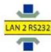
DDC/CI WMI 公司

RS232 WMI 全国

。DusLReIgUeHdAaHJtHnAGuHnEeHnEeHnEeHnEeHnEeHnEeHnEeHnEeHnEeHnEeHnEeHnEeHnEeHnEeHnEeHnEeHnEeHnEeHnEeHnEeHnEeHnEeHnEeHnEeHnEeHnEaeHnEaeHnEaeHnEaeHnEaeHnEaeHnEaeHnEaeHnEaeHnEaeHnEaeHnEaeHnEaeHnEaeHnEaeHnEaeHnEaeHnEaeHnEaeHnEaeHnEaeHnEaeHnEaeHnEaeHnEaeHnEAE
- SBC(단일본 키우터)서 LAN 썼을通過 SBC와 썼 defe고, RS232을 three the main character of the first time. The first time, the first time, the first time, the first time, the first time, the first time, the first time, the first time, the first time, the first time, the first time, the first time, the first time, the first time, the first time, the first time, the first time, the first time, the first time, the first time, the first time, the first time, the first time, the first time, the first time, the first time, and the first time.
。DusLREIgEADHJAEHJNAGUeHJ59EETTtOHaSHiSiO.

中
制在的成的当,
NEC トロiekト
NeTREKJFJLJFJFJFJFJFJFJFJFJFJFJFJFJFJFJFJFJFJFJFJFJFJFJFJFJFJFJFJFJFJFJFJFJFJFJFJFJFJFJFJFJFJFJFJ
- NaViSet Administrator 2
- User's Guide
- User's Guide English
- Software Updates
- Technical Support and Feedback
- Trademarks and Copyright
- Copyright © 2023 Sharp NEC Display Solutions, Ltd.
- Contents
- Chapter 1 Introduction to NaViSet Administrator 9
- Chapter 2 User Interface Overview 15
- Chapter 3 Devices
- 24
- Chapter 4 Configuring Devices 44
- Chapter 5 Controlling Devices 68
- Chapter 6 Credential Library 78
- Chapter 7 Tasks 81
- Chapter 8 Reports
- Chapter 9 Preferences
- Chapter 10 Usage examples
- Chapter 11 Frequently Asked Questions
- Precautions
- Supported Devices
- PN-ME652
- Note:
- System Requirements
- Introduction to NaViSet Administrator
- Introduction
- Features
- Communications
- Adding Devices
- Database
- Advanced Computer Monitoring and Control (Windows version only)
- Speed
- Benefits of using NaViSet Administrator
- Installing NaViSet Administrator
- NaViSet Administrator System
- Components for Remote Windows Based Computers
- Configuration Overview
- Chapter
- 2
- User Interface Overview
- Main Window
- Device Tree
- Groups
- Devices
- = Monitor ID number of the connected display
- Device Connection Status
- Device Communications Status
- Dock Window Area
- Device Properties Window
- Task Manager Window
- Report Manager Window
- Menu
- File menu
- Edit menu
- View menu
- Devices menu
- Tasks menu
- Reports menu
- Tools menu
- Help menu
- Windows computers (Windows version only)
- NEC large-screen displays
- NEC projectors
- PJLink compatible devices
- Adding Single devices
- Adding a single Windows computer on LAN (WMI) (Windows version only)
- Troubleshooting
- Adding NEC large-screen display(s) connected to LAN
- Select NEC large-screen display connected to LAN.
- Browse for NEC Large-Screen Display Dialog
- About Daisy Chain Hosts
- Adding a single NEC projector connected to LAN
- Browse for NEC Projector Dialog
- Adding a single PJLink device connected to LAN
- Select PJLink device connected to LAN.
- Adding Multiple Devices
- Importing Devices - Device Validation mode
- Step 1: Importing Devices
- Step 2: Verifying the Devices
- Step 3: Adding the Devices to the Device Tree
- Refreshing Device Information
- Importing multiple Windows computers (WMI) (Windows version only)
- >Method1:Addcomputersusing"ActiveDirectory
- Active Directory Query Dialog
- >Method 2:Add computers using "Network Enumeration"
- Network Enumeration Dialog
- >Method 3:Add computers using "Import from File"
- Method 4: Add computers using "IP Address Range"
- Importing multiple NEC large-screen displays
- Import Devices Dialog - NEC large-screen displays
- Method 3: Add NEC large-screen displays using "IP Address Range"
- Importing multiple NEC projectors
- >Method 1:Add NEC projectors using "Network Enumeration"
- >Method 2:Add NEC projectors using "Import from File"
- Method 3: Add NEC projectors using "IP Address Range"
- Importing multiple PJLink devices
- >Method 1:Add PJLink devices using "Import from File"
- Import Devices Dialog - PJLink Devices
- >Method 2:Add PJLink devices using "IP Address Range"
- Configuring devices
- Desktop Displays (Windows version only)
- PJLink Devices
- Desktop display(s) connected to a Windows Computer
- Configuration Features
- Adding device(s) to NaViSet Administrator
- Connection Diagram
- Restrictions
- Notes
- Windows Computer on LAN connections via WMI
- Configuring and connecting NEC large-screen displays
- About Monitor IDs
- Connecting Directly to LAN
- Connecting via an RS232 Daisy chain
- Connecting via a LAN Daisy chain
- >Option 1-Direct (recommended):
- >Option 2-Via Translation:
- Using the Auto ID function with a LAN daisy chain
- NEC large-screen display(s) using direct LAN connection
- NEC large-screen display(s) with LAN hub using direct LAN connection
- NEC large-screen display(s) using LAN to RS232 Bridge
- NEC large-screen display(s) with LAN hub using LAN to RS232 Bridge
- NEC large-screen display(s) using RS232 WMI Provider
- NEC large-screen display(s) with SBC and dual LAN connections
- Supported Display Connection Configurations
- NEC large-screen display with SBC and single LAN connection
- NEC projector using direct LAN connection
- NEC projector connected via Windows Computer to LAN
- PJLink compatible device using direct LAN connection
- Available Functions
- 5
- Controlling Devices
- Read-only displays (Windows version only)
- Interactive Control
- Info Property Tab
- Windows Computer Info
- Projector or Large-screen Display Info
- Desktop Display Info
- PJLink Device Info
- Standard Refresh vs. Full Refresh
- Grouped Controls Tabs
- Controls Context Menu
- Display Schedule Property Tab
- Holiday and Weekend Schedules
- Holidays
- Weekends
- Custom Property Tab
- Asset Tag
- Sync Clock with System Date/Time
- TV Channel
- 6
- Credential Library
- About the Credential Library
- Using the Credential Library
- Credentials for Windows computer on LAN (Windows version only)
- Adding a new credential
- Editing an existing credential
- Deleting an existing credential
- Credentials for PJLink Devices
- Tasks
- About Tasks
- Task Library
- Task Manager
- Inactive Tasks list
- Active Task list
- Alerts list
- Creating Tasks
- Creating a New Command Task
- Settings Tab
- Devices Tab
- Commands Tab
- Specific vs. Generalized Controls
- Copying settings from other Devices
- Display Schedule Tab
- IR Remote Tab
- Notifications Tab
- Options are:
- Run Schedule Tab
- Summary Tab
- Creating Conditional Tasks
- Actions Tab
- Creating Informational Tasks
- Task History
- Proof of Play
- Configuring Proof of Play
- Determining Polling Time Interval
- Event Log Window
- POP Tab
- Reports
- About Reports
- Report Library
- Report Manager
- Inactive Reports list
- Active Reports list
- Creating Reports
- Query Items Tab
- Output Tab
- Report History
- 9
- Preferences
- About
- General Settings
- Email Settings
- Database Settings
- Folders
- Language
- Usage examples
- Example Task: Turn displays on and off at set times every weekday
- Example Task: Check for projector lamps close to needing replacement
- Example Task: Check for displays reporting a diagnostic error condition
- Example Task: Configure new displays with multiple preset settings
- Example Task: Using Device Specific controls to configure a Tile Matrix
- Example Task: Check computer conditions and reboot if necessary
- Example Report: Query basic device information and export to Excel
- Frequently Asked Questions
- Answer:
- Problem: Unable to connect to a Windows Computer via WMI
- Windows Computers Only
- Problem: Unable to communicate with an NEC large-screen display
- Problem: Unable to communicate with an NEC projector
- Comparison of connection methods for NEC large-screen displays
- Daisy Chain RS232 vs. Individual LAN Connections
- Wake-on-LAN (WoL) Configuration
- Using Open Hardware Monitor
- Installing and Configuring Open Hardware Monitor
- Supported Sensors
- Using in Tasks and Reports
- LAN to RS232 Bridge Configuration
- Operation
- Limitations
- Configuring the LAN to RS232 Bridge
- Troubleshooting the LAN to RS232 Bridge
- RS232 WMI Provider Configuration
- Configuring
- Advanced Settings
- Create virtual instance for Monitor ID "All" if two or more displays are on a COM port
- Disable Factory Reset Command
- Create instances even if no display monitor is detected
- Windows Management Instrumentation
- About WMI
- NaViSet Administrator WMI Providers
- WMI VB Scripts
- Sample VB Script files included:
- Glossary
- NEC
- NaViSet Administrator-WMI Provider
- Configuration Wake-on-LAN (WoL)
- Configuration de LAN to RS232 Bridge
- A propos
- デバイスのプロバチウインドウ
- NaViSet Administrator WMI Provider
- 用户指南
- 简体中文
- 软件更新
- NaViSet Administrator 简介
- 简介
- "Active Directory 查询”对话框
- LAN to RS232 Bridge 配置
- 关于
- 配置 LAN to RS232 Bridge
- LAN to RS232 Bridge 故障排除
- 사용자 가이드 한국어
- SófrénteWeyerJenldeaiTe
- 将吉用贝
- 目录
- 卍の)s
- 今丘
- NaViSet Administrator的首撮
- NaViSet Administrator 耳声咔
- 中
- NEC トロiekト
Brand : NEC
Model : NaViSet Administrator 2
Category : Software license & extension