RN6045 - Industrial sensor IFM - Free user manual and instructions
Find the device manual for free RN6045 IFM in PDF.
| Technical Features | Not specified |
|---|---|
| Usage | Not specified |
| Maintenance and Repair | Not specified |
| Safety | Not specified |
| General Information | Not specified |
Frequently Asked Questions - RN6045 IFM
Download the instructions for your Industrial sensor in PDF format for free! Find your manual RN6045 - IFM and take your electronic device back in hand. On this page are published all the documents necessary for the use of your device. RN6045 by IFM.
USER MANUAL RN6045 IFM
- Supply voltage and number of steps according to the type label.
- Max. permissible mechanical: 10,000min
- The outputs are protected against a short circuit between the out- puts and U
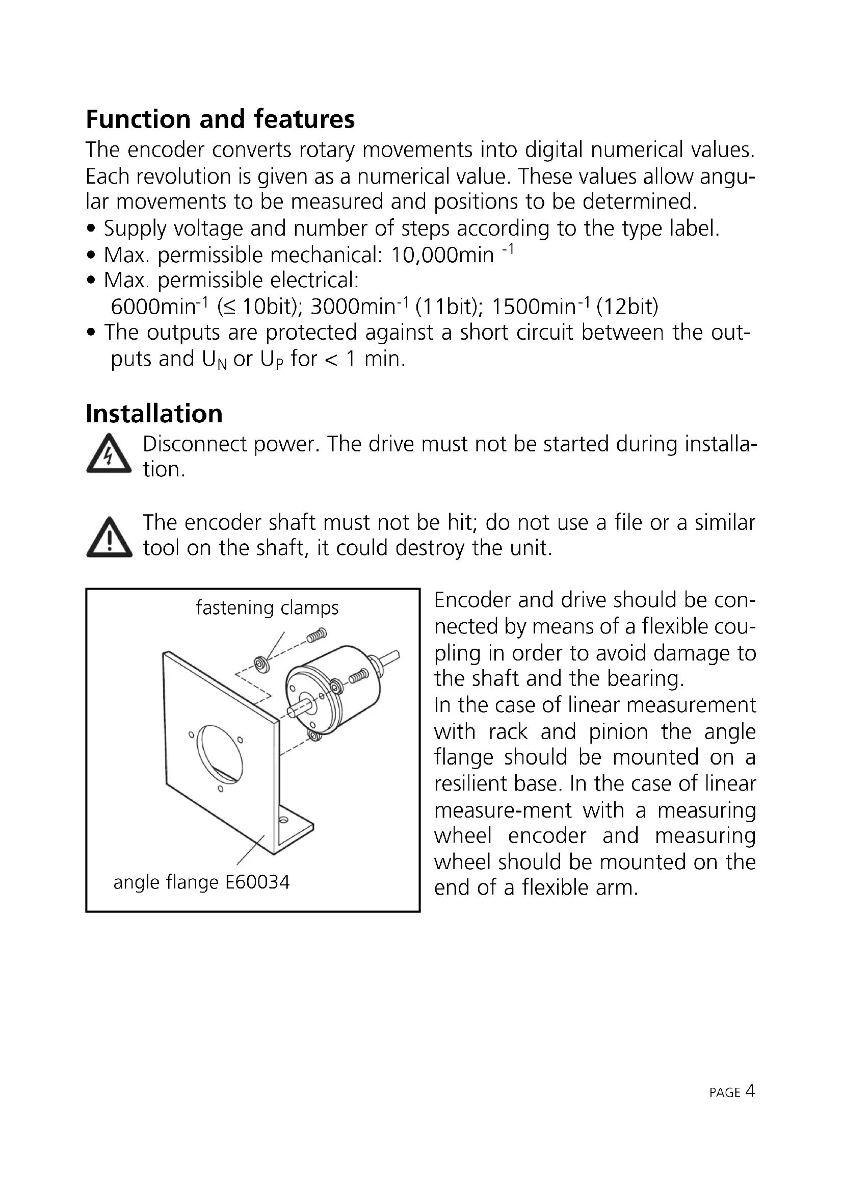
for < 1 min. Installation Disconnect power. The drive must not be started during installa- tion. The encoder shaft must not be hit; do not use a file or a similar tool on the shaft, it could destroy the unit. Encoder and drive should be con- nected by means of a flexible cou- pling in order to avoid damage to the shaft and the bearing. In the case of linear measurement with rack and pinion the angle flange should be mounted on a resilient base. In the case of linear measure-ment with a measuring wheel encoder and measuring wheel should be mounted on the end of a flexible arm. PAGE
fastening clamps angle flange E60034Electrical connection Disconnect power before connection /disconnection of the cable or plug and socket connection. Output signals:
- 5V version: TTL output, 6mA
- 10-30V version: HTL output 20mA, short-circuit protection Extension by means of a screened extension cable; max. length 20m (5V version), 100m (10-30V version); lay separately from sources of interference (min. spacing approx. 20cm). Connect the encoder hous- ing, the connector / terminal box and the evaluation electronics via the screen. Pulse diagram PAGE 5
M4 5 deep B = 10 → C = 6 B = 20 → C = 10 A = 51 (5V /8...12bit) (10-30V / 8...10bit) A = 62 (10-30V /11...12bit)Release When unused or at 0 V the data are permanently present at the out- put. At high level the tracks are blocked. MSB (change the direction of rotation) For encoders with 8, 9 and 10 bits the direction of rotation can be selected via the connection: connection MSB = clockwise rotation connection MSB = anticlockwise rotation PAGE
- high-impedance signal outputs
- release A = low: tracks 3 to 10 to output (8... 10bit version) tracks 7 to 12 to output (11 and 12bit TTL version)
- release B = low: tracks 1 to 2 to output (8 ... 10bit version) tracks 1 to 6 to output (11 and 12bit TTL version)