
Kaoss Mixer - DJ Equipment KORG - Free user manual and instructions
Find the device manual for free Kaoss Mixer KORG in PDF.

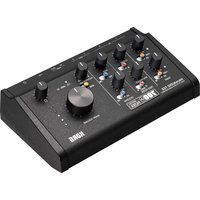
| Product Type | DJ mixer with effects processor |
| Brand | Korg |
| Model | Kaoss Mixer KM-2 |
| Dimensions (W x D x H) | 218 mm x 206 mm x 90 mm |
| Weight | 1.8 kg |
| Power supply | 9V AC power adapter (included) |
| Power consumption | 12.3 W |
| Number of channels | 2 stereo channels |
| Inputs | 2 x PHONO (RCA), 2 x LINE (RCA), 1 x MIC (6.35 mm jack) |
| Outputs | MASTER (RCA), BOOTH (RCA), PHONES (6.35 mm jack) |
| Equalizer per channel | 3 bands: High, Mid, Low |
| Built-in effects | 80 programs split into 8 groups (Filter, Modulation, BPM FX, Delay, Reverb, SFX, X-Fade, Sample/Play) |
| Sampling | 44.1 kHz sampling rate, 20-bit resolution |
| Maximum recording time | 23.7 seconds (4 banks of 6 seconds) |
| Crossfader | Calibratable, selectable curve |
| BPM function | Automatic detection and tap input |
| Touch panel | Effect control on X/Y axes |
| Program maps | 8 memories for quick recall of favorite effects |
| Maintenance | Clean with a dry cloth, do not use solvents |
| Included accessories | Power adapter, touch panel protective sheet |
Frequently Asked Questions - Kaoss Mixer KORG
User questions about Kaoss Mixer KORG
0 question about this device. Answer the ones you know or ask your own.
Ask a new question about this device
Download the instructions for your DJ Equipment in PDF format for free! Find your manual Kaoss Mixer - KORG and take your electronic device back in hand. On this page are published all the documents necessary for the use of your device. Kaoss Mixer by KORG.
USER MANUAL Kaoss Mixer KORG
Using the unit in the following locations can result in a malfunction.
In direct sunlight
- Locations of extreme temperature or humidity
- Excessively dusty or dirty locations
- Locations of excessive vibration
Power supply
Please connect the designated AC/AC adaptor to an AC outlet of the correct voltage. Do not connect it to an AC outlet of voltage other than that for which your unit is intended.
Interference with other electrical devices
This product contains a microcomputer. Radios and televisions placed nearby may experience reception interference. Operate this unit at a suitable distance from radios and televisions.
Handling
To avoid breakage, do not apply excessive force to the switches or controls.
Care
If the exterior becomes dirty, wipe it with a clean, dry cloth. Do not use liquid cleaners such as benzene or thinner, or cleaning compounds or flammable polishes.
Keep this manual
After reading this manual, please keep it for later reference.
Keeping foreign matter out of your equipment
- Never set any container with liquid in it near this equipment. If liquid gets into the equipment, it could cause a breakdown, fire, or electrical shock.
- Be careful not to let metal objects get into the equipment. If something does slip into the equipment, unplug the AC/AC adaptor from the wall outlet. Then contact your nearest Korg dealer or the store where the equipment was purchased.
THE FCC REGULATION WARNING (for U.S.A)
This equipment has been tested and found to comply with the limits for a Class B digital device, pursuant to Part 15 of the FCC Rules. These limits are designed to provide reasonable protection against harmful interference in a residential installation. This equipment generates, uses, and can radiate radio frequency energy and, if not installed and used in accordance with the instructions, may cause harmful interference to radio communications. However, there is no guarantee that interference will not occur in a particular installation. If this equipment does cause harmful interference to radio or television reception, which can be determined by turning the equipment off and on, the user is encouraged to try to correct the interference by one or more of the following measures:
- Reorient or relocate the receiving antenna.
- Increase the separation between the equipment and receiver.
- Connect the equipment into an outlet on a circuit different from that to which the receiver is connected.
- Consult the dealer or an experienced radio/TV technician for help.
Unauthorized changes or modification to this system can void the user's authority to operate this equipment.
CE mark for European Harmonized Standards
CE mark which is attached to our company's products of AC mains operated apparatus until December 31, 1996 means it conforms to EMC Directive (89/336/EEC) and CE mark Directive (93/68/EEC). And, CE mark which is attached after January 1, 1997 means it conforms to EMC Directive (89/336/EEC), CE mark Directive (93/68/EEC) and Low Voltage Directive (73/23/EEC).
Also, CE mark which is attached to our company's products of Battery operated apparatus means it conforms to EMC Directive (89/336/EEC) and CE mark Directive (93/68/EEC).
NOTICE
KORG products are manufactured under strict specifications and voltages required by each country. These products are warranted by the KORG distributor only in each country. Any KORG product not sold with a warranty card or carrying a serial number disqualifies the product from the manufacturer's/distributor's warranty and liability. This requirement is for your own protection and safety.
GENERAL CONTENS
OWNER'S MANUAL / ENGLISH 2-8
NOTICE D'EMPLOI / FRANCAIS 1-8
Connections and controls of the KM-2 2
Effect program list 4
Operation 5
Calibrating the crossfader 7
Specifications 8
Connections and controls of the KM-2
Top panel
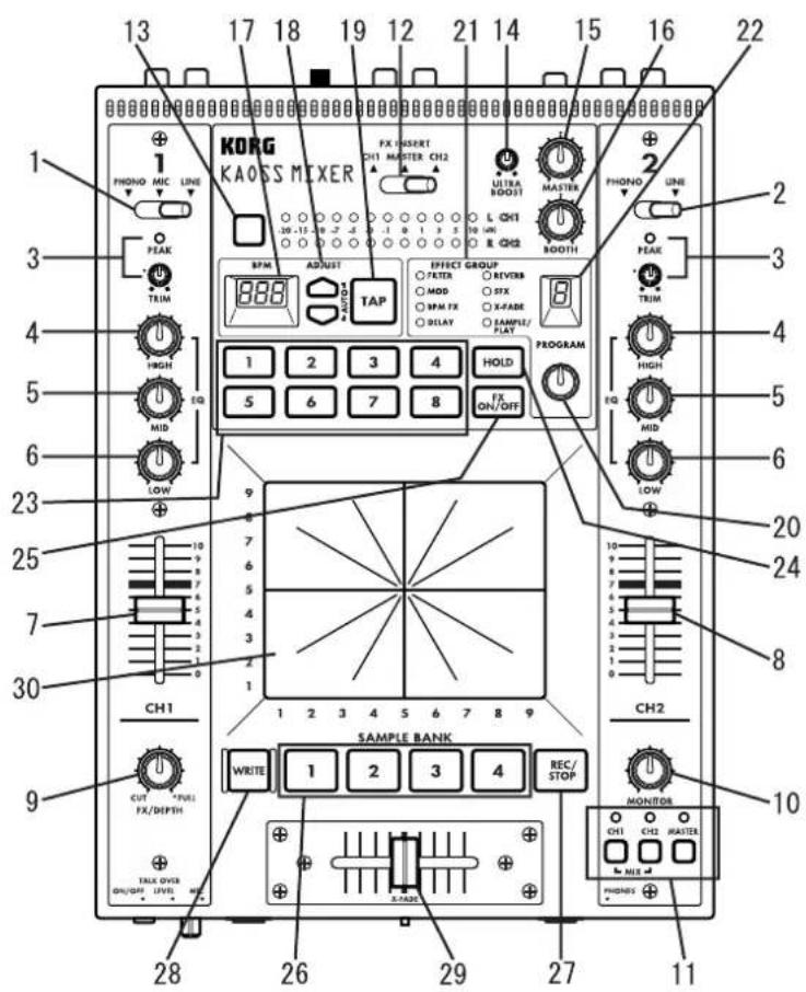
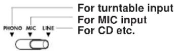
- Channel 1 input select switch
Selects the input source for channel 1.
Note: If you wish to select the mic as the input source, set the front panel TALK OVER ON/OFF switch (F1) to the OFF position.
LINE: CD player, etc. MIC: mic
PHONE: turntable
TALKOVERONOFF
- Channel 2 input select switch
Selects the input source for channel 2.
-
PEAK (peak indicator), TRIM (trim knob) Adjust the trim knob so that the peak indicator does not light even for high volum levels.
-
HIGH EQ (high equalizer)
Adjusts the amount of boost/cut for the high range equalizer.
- MID EQ (middle equalizer)
Adjusts the amount of boost/cut for the mid range equalizer.
- LOW EQ (low equalizer)
Adjusts the amount of boost/cut for the low range equalizer.
- Channel 1 fader
Adjusts the volume of channel 1.
- Channel 2 fader
Adjusts the volume of channel 2.
- FX DEPTH (effect depth) knob
At the CUT position, no effect will be applied to the sound. At the FULL position, the maximum effect will be applied to the sound. Normally you will leave this in the FULL position.
Front panel
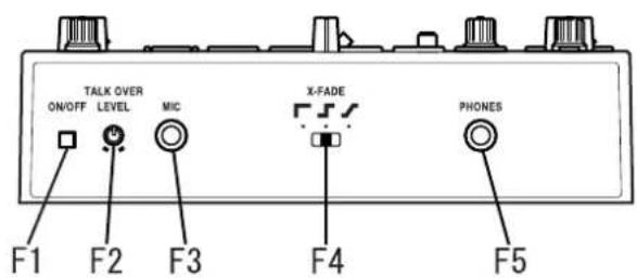
F1. TALK OVER ON/OFF switch
When this switch is ON (pressed in), the audio from the mic input will be mixed into the master output.
If you are using the mic as the input for channel 1, set the TALK OVER switch to OFF.
F2. MIC LEVEL knob
Adjusts the volume level of the mic.
F3. MIC input jack
Connect a mic to this jack.
Note: The mic input is an unbalanced input.
F4. X-FADE (cross fade curve switch)
Selects the curve of the cross-fader.
F5. PHONES (headphone) jack
Connect a set of headphones to this jack.
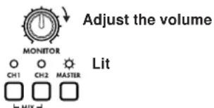
- MONITOR knob
Adjusts the output level of the front panel PHONES jack (F5).
- Monitor select switch
CH1: Monitor the sound of channel 1.
CH2: Monitor the sound of channel 2.
MASTER: Monitor the sound that is being sent to the master output.
MIX (press CH1 and CH2 simultaneously): Monitor the sound of channel 1 in the L channel of the headphones, and the sound of channel 2 in the R channel.
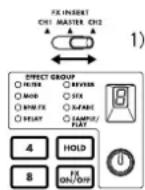
- FX INSERT (effect insert) switch
CH1: Insert the effect at the pre-fader location of channel 1.
CH2: Insert the effect at the pre-fader location of channel 2.
MASTER: Insert the effect at the master (after the cross-fader) location.
For some special effect programs, the effect will be inserted at a different location. (Refer to p.4 "Effect program list.")
- Level meter mode switch
Selects the display mode of the level meter. Each time you press this switch, the following two display modes will be selected alternately.
CH1/CH2: The meters will display the input levels of channels 1 and 2 (pre-fader) respectively.
L/R: The meters will display the L channel and R channel levels of the master output. Use CH1/CH2 at a maximum of 0 dB~1 dB.
- ULTRA BOOST knob
Adjusts the strength of the newly developed Ultra Boost effect. Turning this knob toward the right will increasingly boost the low frequency range and simultaneously emphasize the edge of the bass drum and bass sounds.
- MASTER volume
Adjusts the volume that is output from the MASTER OUTPUT jacks (R6).
- BOOTH volume
Adjusts the volume that is output from the BOOTH OUTPUT jacks (R7).
- BPM display
Displays the tempo of the song; i.e., the BPM.
- ADJUST (BPM adjust) keys
These keys make fine adjustments to the BPM set by the TAP key (19) or by auto BPM detection.
increases the BPM value (makes the tempo faster)
decrease the BPM value (makes the tempo slower)
- TAPkey
When you tap this key twice or more in time with the beat of the song, that beat will be detected and the corresponding tempo displayed in the BPM display (17).
The detectable range of BPM is 40~999.
For details on the BPM function, refer to p.5 "About the BPM function."
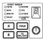
- Effect program knob
Rotate this knob to select an effect program. Effect programs are organized into eight groups such as FILTER or MOD (modulation), and each group contains ten programs, providing a total of 80 preset programs.
- Effect group display
This indicates the name of the currently selected effect program group.
- Effect number display
This shows the currently selected effect program number.
For details on the effects provided by each program, refer to p.4 "Effect program list."
- Program map keys 1-8
Of the 80 effect programs, you can assign eight of your favorite programs to the program map keys for immediate selection.
- HOLD switch
While this switch is lit, the touch panel (30) will be in the Hold state. In this state, the previous state of the effect will be maintained even when you remove your finger from the touch panel.
- FX ON/OFF (effect on/off) switch
Each time you press this switch, it will alternate between lit (effect on) and dark (effect off).
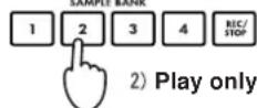
- SAMPLE BANK keys 1-4
Sampled phrases are stored in these keys. If an effect program other than SAMPLE/ PLAY is selected, the stored phrase will play back as long as you hold down the corresponding key 1-4.
The playback sound will be output to the channel that is selected by the FX INSERT switch (12).
☆ You can also use the touch panel to apply an effect to the playback.
- REC/STOP (record) key
When a SAMPLE/PLAY effect program is selected, recording will begin when you press this key. Recording will end when you press this key once again.
For details refer to p.6, "About the SAMPLE/PLAY effects."
- WRITE key
Newly sampled phrases will be lost when the power is turned off. If you wish to keep the phrases, you must write them into memory. For details on the Write procedure, refer to p.7 "Saving your samples."
- X-FADE (crossfader)
This sets the mixing ratio of channel 1 and channel 2.
- Touch panel
Use this to modify the sound of the effect.
Rear panel
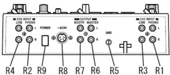
R1. CH1 PHONO (channel 1 phono input jacks)
R2. CH2 PHONO (channel 2 phono input jacks)
Turntables can be connected to these jacks.
R3. CH1 LINE IN (channel 1 line input jacks)
R4. CH2 LINE IN (channel 2 line input jacks)
CD players etc. can be connected to these jacks.
R5. GND (ground) connector
Connect the GND (ground) connector of your turntable(s) to this connector.
R6. MASTER OUTPUT jacks
These jacks output the volume adjusted by the MASTER volume (15).
R7. BOOTH OUTPUT jacks
These jacks output the volume adjusted by the BOOTH volume (16).
R8. AC9V (power supply) connector
Connect the included power adaptor to this connector.
R9. POWER switch
☆ It will take up to 10 seconds after the power is turned on for the KM2 system to begin operating and be ready to use.
Effect program list
KM-2 EFFECT PROGRAM LIST
| EFFECT GROUP PROG TITLE X Y BPM | ↔ | ∅ | ||||||
| FILTER 0 RESONANCE FILTER FREQUENCY RESONANCE | ||||||||
| 1 ISOLATOR LPF/HPF TYPE HI CUT ↔ LOW CUT NO ASSIGN | ||||||||
| 2 WAH FILTER SPEED DEPTH | ||||||||
| 3 DIS†+VOICE FILTER TALKING | DISTORTION | |||||||
| 4 DIS†+FILTER FREQUENCY DISTORTION | ||||||||
| 5 MANUAL PHASER FREQUENCY RESONANCE | ||||||||
| 6 PAN BY HPF X-FADE | PAN | |||||||
| 7 DIS†+ISOLATOR LOW-MID-HI | DISTORTION | |||||||
| 8 MID FREQ ISOLATOR MID BOOST←>CUT | NO ASSIGN | |||||||
| 9 3B AND ISOLATOR HI CUT ↔ LOW CUT MID LEVEL | ||||||||
| MODULATION | 0 VIBRATE | SPEED DEPTH | ||||||
| 1 PHASER | SPEED FREQUENCY | |||||||
| 2 AUTO PAN | LFO SPEED | |||||||
| 3 FLANGER+FILTER | FLANGER SPEED | |||||||
| 4 DIS†+PHASER FREQUENCY FX LEVEL | ||||||||
| 5 MANUAL FLANGER1 | DELAY TIME | |||||||
| 6 MANUAL FLANGER2 | DELAY TIME | |||||||
| 7 PITCH SHIFT LCH | Pitch | |||||||
| 8 TREMOLO | SPEED DUTY | |||||||
| 9 STEP PHASER MOD STEP FREQUENCY | ||||||||
| BPM FX | 0 | BPM DELAY1 | X1-3 1/4BEAT | X3-5 1/2 BEAT | X5-7 1/3 BEAT | X7-9 3/4 BEAT | FEEDBACK | ○ DELAY TIME |
| 1 | BPM DELAY2(TAPE ECHO TYPE) | X1-3 1/4BEAT | X3-5 1/2 BEAT | X5-7 1/3 BEAT | X7-9 3/4 BEAT | FEEDBACK | ○ DELAY TIME | |
| 2 | BPM MULTI TAP DELAY1 | NO ASSIGN | LEVEL | ○ DELAY TIME | ||||
| 3 | BPM MULTI TAP DELAY2 | NO ASSIGN | LEVEL | ○ DELAY TIME | ||||
| 4 | BPM MULTI TAP DELAY3 | NO ASSIGN | FEEDBACK | ○ DELAY TIME | ||||
| 5 | BPM PHASER | X1-3 x2BEAT | X3-5 x1 BEAT | X5-7 1/2 BEAT | X7-9 1/4 BEAT | RESONANCE | ○ SPEED | |
| 6 | BPM FLANGER | X1-3 x2BEAT | X3-5 x1 BEAT | X5-7 1/2 BEAT | X7-9 1/4 BEAT | RESONANCE | ○ SPEED | |
| 7 | BPM TREMOLO | X1-3 x1BEAT | X3-5 1/2 BEAT | X5-7 1/4 BEAT | X7-9 1/8 BEAT | DEPTH | ○ SPEED | |
| 8 | BPM STEP PHASER FREQUENCY(MANUAL) | RESONANCE | ○ SPEED | |||||
| 9 | BPM STEP FLANGER | STEP SPEED | RESONANCE | ○ SPEED | ||||
| DELEY | 0 | TAPE ECHO | DELAY TIME | FX LEVEL,FEEDBACK | ||||
| 1 DELAY | DELAY TIME | |||||||
| 2 DELAY | DELAY TIME | |||||||
| 3 DELAY (POST FADER TYPE) | TONE | |||||||
| 4 MULTI TAP DELAY | TONE | |||||||
| 5 LONG DELAY | FEEDBACK | |||||||
| 6 PING PONG DELAY | DELAY TIME | |||||||
| 7 TALK MODE-DELAY | TALKING | |||||||
| 8 FILTER + DELAY | FILTER FREQ RESONANCE | |||||||
| 9 DUS+DELAY DELAY TIME | TONE | |||||||
| REVERB | 0 HALL REVERB | TONE | ||||||
| 1 GATE REVERB1 | TONE | |||||||
| 2 PLATE REVERB | REV TIME | |||||||
| 3 GATE REVERB2 | FREQUENCY REVERB LEVEL | |||||||
| 4 REVERB+DELAY | DELAY FEEDBACK | |||||||
| 5 REVERB+DELAY | DELAY TIME | |||||||
| 6 TALK MODE-REVERB | TALKING | |||||||
| 7 FILTER+REVERB | FILTER FREQ REVERB LEVEL | |||||||
| 8 3D PAN | L<-R PAN | |||||||
| 9 ROOM REVERB | TONE | |||||||
| SFX | 0 STEP MODULATION | MOD DEPTH | FX LEVEL | |||||
| 1 RING MOD+FILTER | RING FREQ | |||||||
| 2 SIN WAVEFORM OSCILLATOR PITCH | ||||||||
| 3 BPN DELAY+ ISOLATOR ISOLATOR LOW-MID-HI | ||||||||
| 4 RING+DELAY TIME | ||||||||
| 5 TREMOLO-DELAY TIME + LFO SPEED | ||||||||
| 6 SPECIAL ECHO TIME | ||||||||
| 7 VOICE OSCILLATOR PITCH | ||||||||
| 8 SQUARE WAVEFORM OSCILLATOR PITCH | ||||||||
| 9 AQUA SPEED FX LEVEL | ||||||||
| X-FADE | 0 | REVERB X FADE1★ | CH1 ∅ | CH2 CH1 ∅ | CH2 CH2 CH2 | REV LEVEL | ||
| 1 | REVERB X FADE2★ | CH1 ∅ | CH2 CH1 ∅ | CH2 CH2 | Y:5-9 CH1 REV LEVEL | |||
| 2 | ISOLATOR X FADE★ | CH1 ∅ | CH2 CH1 ∅ | CH2 CH2 | Y:1-5 CH2 REV LEVEL | |||
| 3 | FILTER X FADE2★ | CH1 ∅ | CH2 CH1 ∅ | CH2 CH2 | Y:5-9 HI CUT (CH1), LOWCUT(CH2) | |||
| 4 | RESONANCE FILTER X FADE★ | CH1 ∅ | CH2 CH1 ∅ | CH2 CH2 | Y:1-5 LOW CUT (CH1), HI CUT(CH2) | |||
| 5 | BPM DELAY X FADE★ | CH1 ∅ | CH2 CH1 ∅ | CH2 CH2 | Y:5-9 LPF FREQ (CH1), LOWCUT(CH2) | |||
| 6 | PHASER X FADE★ | CH1 ∅ | CH2 CH1 ∅ | CH2 CH2 | PHASING LEVEL | |||
| 7 TAPE ECHO X FADE★ | CH1 ∅ | CH2 CH1 ∅ | CH2 CH1 ∅ | CH2 CH2 | DRY/WET BALANCE | |||
| 8 FLANGER+REV X FADE★ | CH1 ∅ | CH2 CH1 ∅ | CH2 CH1 ∅ | CH2 CH2 | FLANGER+REV LEVEL | |||
| 9 STEP MOD X FADE★ | CH1 ∅ | CH2 CH1 ∅ | CH2 CH1 ∅ | CH2 CH2 | STEP MOD LEVEL | |||
| SAMPLE/PLAY | 0 | LOOP1(AUTO REC START) | LOOP END TIME CONTROL | PLAYBACK LEVEL | ||||
| 1 FORWARD & REVERSE | FORWARD & REVERSE | PLAYBACK LEVEL | ||||||
| 2 FORWARD & REVERSE(HI SPEED) | FORWARD & REVERSE | PLAYBACK LEVEL | ||||||
| 3 SCRAWTHING | SCRAWTHING | Y:5-9 GATE ON Y1-5:GATE OFF | ||||||
| 4 SCRAWTHING WITH FILTER | SCRAWTHING | FILTER FREQ | ||||||
| 5 TIME STRETCH | SLOW ∅-FAST TEMPO | PLAYBACK LEVEL | ||||||
| 6 SCRAWTHING WITH BPM DELAY ★ | SCRAWTHING | DELAY LEVEL | ○ DELAY TIME | |||||
| 7 LOOP2 | LOOP START TIME CONTROL | PLAYBACK LEVEL | ||||||
| 8 FORWARD & REVERSE with DELAY | FORWARD & REVERSE | PLAYBACK LEVEL | ||||||
| 9 FORWARD&REVERSE with SFX | FORWARD & REVERSE | SFX CONTROL | ||||||
About programs marked by ★
Regardless of the FX INSERT location, the sample will be recorded from MASTER, and when monitoring CH1, CH2 or CH1&2 from the PHONES jack, the sound will be monitored without delay rever
applied
About AUTO REC START
When SAMPLE/PLAY number 0 is selected, recording will use AUTO REC START. After the REC key is pressed, recording will begin automatically when a signal is input.
For the X-FADE effect group and for DELAY-3, the effect will not be applied to the sample playback sound when the FX INSERT switch is set to MASTER.
Operation
Basic operation
1) As described in "Connections and controls of the KM-2" (p.2), connect your turntable(s) or CD player(s) to CH1 and CH2. Set the input select switches (1, 2) to the appropriate position for the devices that are connected to channels 1 and 2.
2) If you are using headphones for listening, connect your headphones to the front panel PHONES jack (F5).
In this explanation we will assume that you are monitoring through headphones.
3) Turn on the POWER switch (R9). It will take up to 10 seconds for the KM-2 system to begin operating and be ready to use. The system has finished starting up when the BPM display stops rotating.
4) Make sure that the monitor select switches (11) are set to MASTER, and use the MONITOR knob (10) to adjust the volume of the headphones.
5) Here's how to monitor the sound of CH1 in the headphones. Set the CH1 fader (7) to approximately 50 70% . If the PEAK LED lights, the input is too loud. Rotate the TRIM knob (3) toward the left until the LED no longer lights. At this time, set X-FADE (29) to the CH1 (left) position.
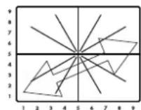
6) Use the touch panel (30) to control the effect.
The effect section of the KM-2 lets you control the sound by moving across the X-axis (horizontal) and Y-axis (vertical) of the touch panel. For details on which effect is in what number, and the parameters that are controlled by the X-axis and Y-axis, refer to p.4 "Effect program list."
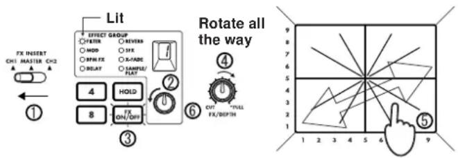
Here's how to apply an effect to the CH1 signal.
1 Set FX INSERT (12) to CH1.
2 For this example, rotate the effect program knob (20) to select program number 1 of the FILTER group.
3 Make sure that the FX ON/OFF switch (25) is lit.
4 Rotate the FX DEPTH knob (9) all the way to the right.
5 Touch the touch panel (30), and the effect will be applied.
6 Rotate the effect program knob (20) to change the program.
About the BPM function
What is BPM?
BPM stands for Beats Per Minute, and indicates the tempo of the song in terms of the number of beats (quarter notes) that occur in one minute.
If BPM = 120 , there will be 120 beats in one minute of the song, meaning that each beat is 0.5 seconds long. Higher BPM values mean that the tempo is faster.
Detecting the BPM
There are two ways to set the BPM: auto BPM detection, or BPM tap input.
Auto BPM
1) Use the FX INSERT switch (12) to select the channel (CH1 or CH2) into which you are inputting the song whose BPM you wish to detect.
2) Simultaneously press the ADJUST and keys (18). This will cause the BPM to be detected automatically and displayed in the BPM indicator (17).
3) Press or to end detection and finalize the BPM.
If you operate the FX INSERT switch (12) or press and simultaneously while auto BPM detection is occurring, auto BPM detection will be cancelled.
Auto BPM detection will not function if the FX INSERT (12) is set to MASTER.
☆ It may not be possible to correctly detect the BPM of songs with complex drum phrases. In such cases, use TAP to input the BPM.
The AUTO BPM detection range is 80-160.
Using TAP to input the BPM
Press the TAP key (19) twice or more in time with the beat of the song. When you do so, that tempo will be displayed in the BPM indicator (17).
BPM input via TAP can be performed even if the FX INSERT switch (12) is set to MASTER.
Fine adjustment of BPM
After the BPM has been detected or set, you can use the ADJUST
switches (18) to make fine adjustments to the BPM setting.
When you switch the setting of the FX INSERT switch (12), the previous BPM detection value for that channel will be displayed.
When performing BPM detection for the first time, the default value will be BPM = 120
BPM effects
If an effect program of the BPM FX group is selected, you can apply an effect that is synchronized to the BPM.
For example with the BPM FX-1 program BPM DELAY2, touching the touch panel (30) in the 3-5 area of the horizontal axis will cause the delay length to be half of the BPM. For details on other BPM effects, refer to p.4 "Effect program list."
If you use the TAP key (19) to input the BPM, the BPM value will be applied to the effect immediately.
If you use auto BPM, the BPM value will be applied to the effect when you press ADJUST (18) or .
About the SAMPLE/PLAY effects
The sampling function of the KM-2 lets you store four different six-second samples.
Recording and playback when a SAMPLE/PLAY effect program is selected
You can record or play back samples when a SAMPLE/PLAY effect program is selected. Playback speed and reverse-playback etc. can be controlled from the touch panel.
Playback control will differ depending on the effect program. Refer to p.4 "Effect program list."
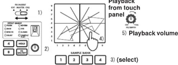
Playback procedure
1) Use the FX INSERT switch (12) to select the channel into which the playback sound will be mixed.
2) Select a program of the SAMPLE/PLAY group.
3) Use the SAMPLE BANK keys 1-4 (26) to select the sample that you wish to play back. (At this time the sample will not play yet.)
4) When you press the touch panel (30), playback will occur according to the location you touched.
5) You can use the FX DEPTH knob (9) to adjust the volume of the playback. When the knob is in the center position, the sample playback sound will be added to the channel input sound in a 1:1 ratio. When the knob is at the maximum position, only the sample will be heard during playback, and the channel input sound will not be heard.
Recording procedure
1) Use the FX INSERT switch (12) to select whether to record the sound of CH1, CH2, or MASTER.
2) Use the effect program knob (20) to select a SAMPLE/PLAY program. For this example, select SAMPLE/PLAY-1.
3) Use the SAMPLE BANK keys 1-4 (26) to select the sample bank 1-4 into which you will record.
4) Press the REC/STOP key (27) to start recording. Recording will end when you press the REC/STOP key once again (or when the maximum recording time has elapsed).
During recording, the REC/STOP key (27) LED will light.
5) Press the touch panel (30), and the recorded phrase will play. The way in which the phrase plays will differ depending on the program. Refer to p.4 "Effect program list."
Recording and playback when a non-SAMPLE/PLAY effect program is selected
You can record and play back phrases (basic playback) even when a non-SAMPLE/PLAY effect program is selected. Playback and recording is not possible when FX is off.
Playback procedure
1) Use the effect program knob (20) to select an effect program from other than the SAMPLE/PLAY group.
2) When you press a SAMPLE BANK key 1-4 (26), the corresponding sample will play back as long as you continue holding that key. However, the sample will play at normal speed, and will loop (play repeatedly) at the volume at which it was recorded.
By operating the touch panel (30) while you play the sample, you can apply an effect to the sample playback.
The playback sound will be mixed into the channel that is selected by the FX INSERT switch (12).

You can apply an effect to the playback sound
1) Select other than SAMPLE/ PLAY
If you press the HOLD switch (24) during playback, the playback will be held. When you press a SAMPLE BANK key 1-4 (26) once again, hold will be defeated.
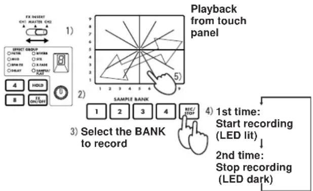
Recording procedure
1) Use the FX INSERT switch (12) to select whether to record the sound of CH1, CH2, or MASTER.
2) Use the effect program knob (20) to select a non-SAMPLE/ PLAY program.
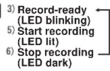
3) Press the REC/STOP key (27) to enter record-ready mode. (You can cancel this state by pressing the FX ON/OFF switch (25).)
The REC/STOP key (27) LED will blink to indicate that you are in record-ready mode.
4) Use the SAMPLE BANK keys 1-4 (26) to select the sample bank 1-4 into which the sample will be stored. (The sample sound will not be heard at this time.)
5) Press the REC/STOP key (27) once again to begin recording.
6) Recording will stop when you press the REC/STOP key (27) once again (or when the maximum recording time has elapsed).
During recording, the REC/STOP key (27) LED will light.
☆ If you wish to re-record, repeat the procedure from step 3.
If you record using a non-SAMPLE/PLAY program, the effect sound as controlled by the touch panel will also be recorded.
2) Select other than SAMPLE/ PLAY

4) Select the BANK to record
Saving a sample - "WRITE"
Phrases that you record using the REC/STOP key are only written temporarily into the internal memory of the KM-2, and will be lost when the power is turned off. If you wish to keep them, you must perform the WRITE operation. Conversely, phrases you have already saved using WRITE will not be erased by additional recording as long as you do not perform the WRITE operation again.
1) Press and hold the WRITE key (28) for two seconds. The WRITE LED will begin blinking, and the KM-2 will be in write-ready mode.
2) Press the SAMPLE BANK key(s) 1-4 (26) that you wish to save. (The SAMPLE BANK you pressed will blink.) You may select two or more banks to write.
If you press the TAP key (19) or the FX ON/OFF switch (25) at this point, the WRITE operation will be cancelled.
3) Press the WRITE key (28) once again, and writing will begin. Writing will require a maximum of 20 seconds per bank. While writing is being performed, the level meter will indicate the progress. When writing is completed, the WRITE key (28) LED will go dark.
Never turn off the power during the writing process. Doing so will cause the data to be lost.
About the program map keys
Your favorite effect programs can be assigned to the program MAP 1-8 keys for quick access. The program map keys store not only the effect program number, but also the HOLD ON/OFF status, the HOLD position, and other data listed below.
Data stored in a program MAP
- Effect program group number
HOLD ON/OFF status and location (coordinates) - For the BPM FX group, the BPM value that was displayed when you stored the MAP
- For the SAMPLE/PLAY group, the SAMPLE BANK number used (the SAMPLE BANK 1-4 that was selected when you stored the memory will be remembered)
Storing to a MAP memory
1) Press the MAP number 1-8 (23) in which you wish to store.
2) Use the effect program knob (20) to select the effect program that you wish to store. If you wish to store with HOLD ON, select the HOLD ON (LED lit) state, and touch the touch panel (30) at the desired coordinates.
3) Press and hold the currently-lit program map key (23) for two seconds. When the MAP LED has blinked three times, the data has been stored.
- At this time, the value in the effect number display will also blink.
Calibrating the crossfader
On the KM-2 you can adjust the point at which CH 1 and CH 2 of the crossfader begin to change. (With the factory settings, the change will begin with minimal movement.)
1) Turn the power off.
2) While holding down the WRITE key (28) and the REC/STOP key (27), turn the power on. When you do so, the BPM display will show "CAL," indicating that you are in Calibration mode.
3) Now if you move the crossfader (29), the LEDs of SAMPLE BANK keys 1-4 (26) will light accordingly. The point at which the light changes from 1 2 is the point at which the crossfader currently starts changing from CH 1 to CH 2. The point at which the light changes from 4 3 is the point at which the crossfader currently starts changing from CH 2 to CH 1.
4) First, move the crossfader to the location at which you want begin changing from CH 1 → CH 2.
5) When you press the REC/STOP key (27), the switching point will be updated.
6) Repeat steps 4 and 5 to set the CH 2 CH 1 point.
7) When you press the WRITE key (28), the data for the specified points will be stored in internal memory, and you will return to normal operating mode.
The switching points cannot be set to a location where BANK LED 2 and 3 are lit simultaneously.
The minimum switching point is approximately 3.0mm from the left or the right. It is not possible to set the switching point closer to the left or right edge. (If you perform step 5 with the crossfader moved all the way to left or right, the switching point will automatically be set to the minimum location.)
The calibration data is preserved even when the power is turned off.
Specifications
Input section
BPM:40~999 (TAP)
80~160 (AUTO)
PHONE INPUT : input impedance 40 k-ohms, reference level -40 dBu
LINE INPUT : input impedance 10 k-ohms, reference level -10 dBu
MIC INPUT : input impedance 9 k-ohms, reference level -40 dBu
MASTER OUTPUT : output impedance 600 ohms, reference level 0 dBu
MONITOR OUTPUT : output impedance 33 ohms
Effect section
Sampling frequency: 44.1 kHz
AD/DA:20bit
Maximum recording time : 23.7 seconds
Effect programs : 80
Program maps : 8
Power consumption : 12.3 W (TYP)
Dimensions : W× D× H = 218mm× 206mm× 90 mm (including protrusions)
Weight : 1.8 kg
Included items : Power supply adaptor
: Touch panel protection sheet
Options : Cross fader unit
Table des matieres
Specifications techniques
Section entrées
BPM:40\~999 (TAP)
80~160 (AUTO)
Sample speichern - "WRITE"
13.5.12.13.14.15.16.17.18.19.20.21.22.23.24.25.26.27.28.29.30.31.32.33.34.35.36.37.38.39.40.41.42.43.44.45.46.47.48.49.50.51.52.53.54.55.56.57.58.59.60.61.62.63.64.65.66.67.68.69.70.71.72.73.74.75.76.77.78.79.80.81.82.83.84.85.86.87.88.89.90.91.92.93.94.95.96.97.98.99.
4.保期期间切九土土修理有料可安分含土,引言结言、品的修理是责任全持之而也之

- Power supply
- Interference with other electrical devices
- Handling
- Care
- Keep this manual
- Keeping foreign matter out of your equipment
- THE FCC REGULATION WARNING (for U.S.A)
- CE mark for European Harmonized Standards
- NOTICE
- GENERAL CONTENS
- Connections and controls of the KM-2
- Top panel
- Front panel
- Rear panel
- Effect program list
- Operation
- Basic operation
- About the BPM function
- What is BPM?
- Detecting the BPM
- Auto BPM
- Using TAP to input the BPM
- Fine adjustment of BPM
- BPM effects
- About the SAMPLE/PLAY effects
- Recording and playback when a SAMPLE/PLAY effect program is selected
- Playback procedure
- Recording procedure
- Recording and playback when a non-SAMPLE/PLAY effect program is selected
- Saving a sample - "WRITE"
- About the program map keys
- Data stored in a program MAP
- Storing to a MAP memory
- Calibrating the crossfader
- Specifications
- Input section
- Effect section
- Table des matieres
- Specifications techniques
- Section entrées
- Sample speichern - "WRITE"
Brand : KORG
Model : Kaoss Mixer
Category : DJ Equipment