USER MANUAL DH24PG(LA) HITACHI
Rotary Hammer
Bohrhammer
Martreau perforateur
Martello perforatore
Boorhamer
Martillo perforador
Martelo perforador
Read all safety warnings and all instructions.
Failure to follow the warnings and instructions may result in electric shock, fire and/or serious injury.
Save all warnings and instructions for future reference.
The term "power tool" in the warnings refers to your mains-operated (corded) power tool or battery-operated (cordless) power tool.
1) Work area safety
a) Keep work area clean and well lit.
Cluttered or dark areas invite accidents.
b) Do not operate power tools in explosive atmospheres, such as in the presence of flammable liquids, gases or dust.
Power tools create sparks which may ignite the dust or fumes.
c) Keep children and bystanders away while operating a power tool.
Distractions can cause you to lose control.
2) Electrical safety
a) Power tool plugs must match the outlet.
Never modify the plug in any way.
Do not use any adapter plugs with earthed (grounded) power tools.
Unmodified plugs and matching outlets will reduce risk of electric shock.
b) Avoid body contact with earthed or grounded surfaces, such as pipes, radiators, ranges and refrigerators.
There is an increased risk of electric shock if your body is earthed or grounded.
c) Do not expose power tools to rain or wet conditions.
Water entering a power tool will increase the risk of electric shock.
d) Do not abuse the cord. Never use the cord for carrying, pulling or unplugging the power tool.
Keep cord away from heat, oil, sharp edges or moving parts.
Damaged or entangled cords increase the risk of electric shock.
e) When operating a power tool outdoors, use an extension cord suitable for outdoor use.
Use of a cord suitable for outdoor use reduces the risk of electric shock.
f) If operating a power tool in a damp location is unavoidable, use a residual current device (RCD) protected supply.
Use of an RCD reduces the risk of electric shock.
3) Personal safety
a) Stay alert, watch what you are doing and use common sense when operating a power tool.
Do not use a power tool while you are tired or under the influence of drugs, alcohol or medication.
A moment of inattention while operating power tools may result in serious personal injury.
b) Use personal protective equipment. Always wear eye protection.
Protective equipment such as dust mask, non-skid safety shoes, hard hat, or hearing protection used for appropriate conditions will reduce personal injuries.
c) Prevent unintentional starting. Ensure the switch is in the off-position before connecting to power source and/or battery pack, picking up or carrying the tool.
Carrying power tools with your finger on the switch or energising power tools that have the switch on invites accidents.
d) Remove any adjusting key or wrench before turning the power tool on.
A wrench or a key left attached to a rotating part of the power tool may result in personal injury.
e) Do not overreach. Keep proper footing and balance at all times.
This enables better control of the power tool in unexpected situations.
f) Dress properly. Do not wear loose clothing or jewellery. Keep your hair, clothing and gloves away from moving parts.
Loose clothes, jewellery or long hair can be caught in moving parts.
g) If devices are provided for the connection of dust extraction and collection facilities, ensure these are connected and properly used.
Use of dust collection can reduce dust related hazards.
a) Do not force the power tool. Use the correct power tool for your application.
The correct power tool will do the job better and safer at the rate for which it was designed.
b) Do not use the power tool if the switch does not turn it on and off.
Any power tool that cannot be controlled with the switch is dangerous and must be repaired.
c) Disconnect the plug from the power source and/or the battery pack from the power tool before making any adjustments, changing accessories, or storing power tools.
Such preventive safety measures reduce the risk of starting the power tool accidentally.
d) Store idle power tools out of the reach of children and do not allow persons unfamiliar with the power tool or these instructions to operate the power tool.
Power tools are dangerous in the hands of untrained users.
e) Maintain power tools. Check for misalignment or binding of moving parts, breakage of parts and any other condition that may affect the power tool's operation.
If damaged, have the power tool repaired before use. Many accidents are caused by poorly maintained power tools.
f) Keep cutting tools sharp and clean.
Properly maintained cutting tools with sharp cutting edges are less likely to bind and are easier to control.
g) Use the power tool, accessories and tool bits etc. in accordance with these instructions, taking into account the working conditions and the work to be performed.
Use of the power tool for operations different from those intended could result in a hazardous situation.
5) Service
a) Have your power tool serviced by a qualified repair person using only identical replacement parts.
This will ensure that the safety of the power tool is maintained.
PRECAUTION
Keep children and infirm persons away.
When not in use, tools should be stored out of reach of children and infirm persons.
ROTARY HAMMER SAFETY WARNINGS
1. Wear ear protectors
Exposure to noise can cause hearing loss.
- Use auxiliary handle(s), if supplied with the tool.
Loss of control can cause personal injury.
- Hold power tool by insulated gripping surfaces, when performing an operation where the cutting accessory may contact hidden wiring or its own cord. Cutting accessory contacting a "live" wire may make exposed metal parts of the power tool "live" and could give the operator an electric shock.
- Do not touch the bit during or immediately after operation. The bit becomes very hot during operation and could cause serious burns.
SPECIFICATIONS
- Before starting to break, chip or drill into a wall, floor or ceiling, thoroughly confirm that such items as electric cables or conduits are not buried inside.
- Always hold the body handle and side handle of the power tool firmly. Otherwise the counterforce produced may result in inaccurate and even dangerous operation.
- Wear a dust mask Do not inhale the harmful dusts generated in drilling or chiseling operation. The dust can endanger the health of yourself and bystanders.
| Model DH24PG DH26PB | DH28PBY | | |
| Voltage (by areas)*1 | (110 V, 115 V, 120 V, 127 V, 220 V, 230 V, 240 V)~ |
| Power Input*1 | 730 W 830 W 850 W | |
| No-load speed*1 | 0 - 1050 min-1 | 0 - 1100 min-1 |
| Full-load impact rate 0 - | 3950 min-1 | 0 - 4300 min-1 |
| Capacity: concrete 3.4 - | 24 mm 3.4 - 26 mm 3.4 - 28 mm |
| steel | 13 mm | 13 mm | 13 mm |
| wood | 32 mm | 32 mm | 32 mm |
| Weight*2 | 2.7 kg | 2.8 kg | 2.9 kg |
1 Be sure to check the nameplate on product as it is subject to change by areas.
2 Weight: According to EPTA-Procedure 01/2003
STANDARD ACCESSORIES
(1) Plastic case 1
(2) Side handle 1
(3) Depth gauge 1
Standard accessories are subject to change without notice.
OPTIONAL ACCESSORIES (sold separately)
Drilling holes in concrete or tile
| Drill bit (slender shaft) |
| Outer dia. | Overall length | Effective length |
| 3.4 mm | 90 mm 45 mm | |
| 3.5 mm | |
| SDS-plus Drill bit |
| Outer dia. | Overall length Effective length |
| 4.0 mm 1 | 10 mm 49 mm | |
| 5.0 mm | 110 mm 49 mm | |
| 160 mm 99 mm | |
| 5.5 mm 1 | 10 mm 50 mm | |
| 6.0 mm | 110 mm 50 mm | |
| 160 mm 100 mm | |
| 6.4 mm 1 | 160 mm 100 mm | |
| 6.5 mm 1 | 160 mm 100 mm | |
| 7.0 mm 1 | 160 mm 100 mm | |
| 7.5 mm 1 | 160 mm 100 mm | |
| 8.0 mm 1 | 160 mm 100 mm | |
| 8.5 mm 1 | 160 mm 100 mm | |
| 9.0 mm 1 | 160 mm 100 mm | |
| 9.5 mm 1 | 160 mm 100 mm | |
| 10.0 mm | 160 mm 100 mm | |
| 260 mm 200 mm | |
| 10.5 mm | 160 mm 100 mm | |
| 260 mm 200 mm | |
| 11.0 mm 1 | 160 mm 100 mm | |
| 12.0 mm | 160 mm 88 mm | |
| 260 mm 187 mm | |
| 12.5 mm | 160 mm 88 mm | |
| 260 mm 187 mm | |
| 12.7 mm | 160 mm 88 mm | |
| 260 mm 187 mm | |
| 13.0 mm 1 | 160 mm 87 mm | |
| 14.0 mm 1 | 160 mm 87 mm | |
| 14.3 mm | 160 mm 87 mm | |
| 260 mm 186 mm | |
| 14.5 mm | 160 mm 87 mm | |
| 260 mm 186 mm | |
| 15.0 mm 1 | 160 mm 85 mm | |
| 16.0 mm | 160 mm 85 mm | |
| 260 mm 186 mm | |
| 16.5 mm 1 | 160 mm 85 mm | |
| 17.0 mm | 160 mm 85 mm | |
| 260 mm 185 mm | |
| 17.5 mm | 160 mm 90 mm | |
| 260 mm 185 mm | |
| 18.0 mm 1 | 160 mm 85 mm | |
| 19.0 mm 2 | 160 mm 185 mm | |
| 20.0 mm 2 | 160 mm 175 mm | |
| 22.0 mm 2 | 160 mm 175 mm | |
| 24.0 mm 2 | 160 mm 173 mm | |
| 25.0 mm 4 | 160 mm 375 mm | |
Large hole boring
| Core bit Outer dia. O | Center pin | Core bit shank |
| 25 mm* | Not applicable | 105 mm300 mm |
| 29 mm* |
| 32 mm | |
| 35 mm (A) |
| 38 mm |
| 45 mm | (B) 300 mm | |
| 50 mm |
Anchor setting
| Anchor setting adapter
Anchor size |
| W 1/4" |
| W 5/16" |
| W 3/8" |
| W 1/2" |
| W 5/8" |
Drilling anchor holes
| Taper shank adapter
Taper mode |
| Morse taper No.1 |
| Morse taper No.2 |
| A-Taper |
| B-taper |
Optional accessories are subject to change without notice.
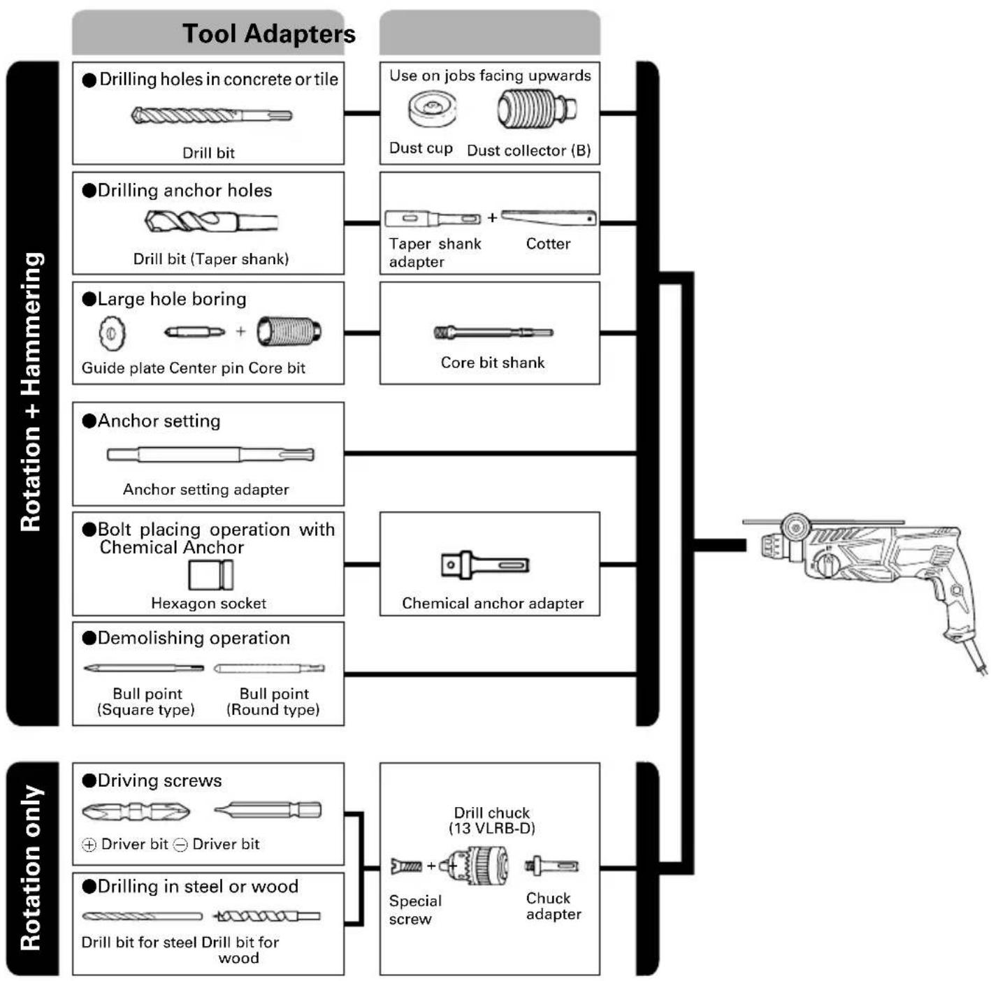
APPLICATIONS
Rotation and hammering function
Drilling anchor holes
Drilling holes in concrete
Drilling holes in tile
Rotation only function
Drilling in steel or wood (with optional accessories)
- Tightening machine screws, wood screws (with optional accessories)
PRIOR TO OPERATION
- Power source
Ensure that the power source to be utilized conforms to the power requirements specified on the product nameplate.
- Power switch
Ensure that the power switch is in the OFF position. If the plug is connected to a power receptacle while the power switch is in the ON position, the power tool will start operating immediately, which could cause a serious accident.
- Extension cord
When the work area is removed from the power source, use an extension cord of sufficient thickness and rated capacity. The extension cord should be kept as short as practicable.
- Mounting the drill bit (Fig. 1)
CAUTION
To prevent accidents, make sure to turn the switch off and disconnect the plug from the receptacle.
NOTE
When using tools such as bull points, drill bits, etc., make sure to use the genuine parts designated by our company.
(1) Clean the shank portion of the drill bit.
(2) Insert the drill bit in a twisting manner into the tool holder until it latches itself (Fig. 1).
(3) Check the latching by pulling on the drill bit.
(4) To remove the drill bit, fully pull the grip in the direction of the arrow and pull out the drill bit (Fig. 2).
5. Installation of dust cup or dust collector (B) (Optional accessories) (Fig. 3, Fig. 4)
When using a rotary hammer for upward drilling operations attach a dust cup or dust collector (B) to collect dust or particles for easy operation.
Installing the dust cup
Use the dust cup by attaching to the drill bit as shown in Fig. 3.
When using a bit which has big diameter, enlarge the center hole of the dust cup with this rotary hammer.
Installing dust collector (B)
When using dust collector (B), insert dust collector (B) from the tip of the bit by aligning it to the groove on the grip (Fig. 4).
CAUTION
The dust cup and dust collector (B) are for exclusive use of concrete drilling work. Do not use them for wood or metal drilling work.
Insert dust collector (B) completely into the chuck part of the main unit.
When turning the rotary hammer on while dust collector (B) is detached from a concrete surface, dust collector (B) will rotate together with the drill bit. Make sure to turn on the switch after pressing the dust cup on the concrete surface. (When using dust collector (B) attached to a drill bit that has more than 190mm of overall length, dust collector (B) cannot touch the concrete surface and will rotate. Therefore please use dust collector (B) by attaching to drill bits which have 166mm , 160mm , and 110mm overall length.)
Dump particles after every two or three holes when drilling.
Please replace the drill bit after removing dust collector (B).
6. Selecting the driver bit
Screw heads or bits will be damaged unless a bit appropriate for the screw diameter is employed to drive in the screws.
- Confirm the direction of bit rotation (Fig. 5)
The bit rotates clockwise (viewed from the rear side) by pushing the R-side of the push button.
The L-side of the push button is pushed to turn the bit counterclockwise.
HOW TO USE
CAUTION
To prevent accidents, make sure to turn the switch off and disconnect the plug from the receptacle when the drill bits and other various parts are installed or removed. The power switch should also be turned off during a work break and after work.
- Switch operation
The rotation speed of the drill bit can be controlled stepplessly by varying the amount that the trigger switch is pulled. Speed is low when the trigger switch is pulled slightly and increases as the switch is pulled more. Continuous operation may be attained by pulling the trigger switch and depressing the stopper. To turn the switch OFF, pull the trigger switch again to disengage the stopper, and release the trigger switch to its original position.
However, the switch trigger can only be pulled in halfway during reverse and rotates at half the speed of forward operation.
The switch stopper is unusable during reverse.
- Rotation + hammering
This rotary hammer can be set to rotation and hammering mode by pressing the push button and turning the change lever to the IT mark (Fig. 6).
(1) Mount the drill bit.
(2) Pull the trigger switch after applying the drill bit tip to the drilling position (Fig. 7).
(3) Pushing the rotary hammer forcibly is not necessary at all. Pushing slightly so that drill dust comes out gradually is sufficient.
CAUTION
When the drill bit touches construction iron bar, the bit will stop immediately and the rotary hammer will react to revolve. Therefore grip the side handle and handle tightly as shown in Fig. 7.
3. Rotation only
This rotary hammer can be set to rotation only mode by pressing the push button and turning the change lever to the mark (Fig. 8).
To drill wood or metal material using the drill chuck and chuck adapter (optional accessories), proceed as follows.
Installing drill chuck and chuck adapter (Fig. 9).
(1) Attach the drill chuck to the chuck adapter.
(2) The part of the SDS-plus shank is the same as the drill bit. Therefore, refer to the item of "Mounting the drill bit" for attaching it.
CAUTION
Application of force more than necessary will not only expedite the work, but will deteriorate the tip edge of the drill bit and reduce the service life of the rotary hammer in addition.
Drill bits may snap off while withdrawing the rotary hammer from the drilled hole. For withdrawing, it is important to use a pushing motion.
Do not attempt to drill anchor holes or holes in concrete with the machine set in the rotation only function.
Do not attempt to use the rotary hammer in the rotation and striking function with the drill chuck and chuck adapter attached. This would seriously shorten the service life of every component of the machine.
4. When driving machine screws (Fig. 10)
First, insert the bit into the socket in the end of chuck adapter (D).
Next, mount chuck adapter (D) on the main unit using procedures described in 4 (1), (2), (3), put the tip of the bit in the slots in the head of the screw, grasp the main unit and tighten the screw.
CAUTION
Exercise care not to excessively prolong driving time, otherwise, the screws may be damaged by excessive force.
Apply the rotary hammer perpendicularly to the screw head when driving the screw; otherwise, the screw head or bit will be damaged, or driving force will not be fully transferred to the screw.
Do not attempt to use the rotary hammer in the rotation and striking function with the chuck adapter and bit attached.
5. When driving wood screws (Fig. 10)
(1) Selecting a suitable driver bit Employ plus-head screws, if possible, since the driver bit easily slips off the heads of minus-head screws.
(2) Driving in wood screws
Prior to driving in wood screws, make pilot holes suitable for them in the wooden board. Apply the bit to the screw head grooves and gently drive the screws into the holes.
After rotating the rotary hammer at low speed for a while until the wood screw is partly driven into the wood, squeeze the trigger more strongly to obtain the optimum driving force.
CAUTION
Exercise care in preparing a pilot hole suitable for the wood screw taking the hardness of the wood into consideration. Should the hole be excessively small or shallow, requiring much power to drive the screw into it, the thread of the wood screw may sometimes be damaged.
6. Using depth gauge (Fig. 11)
(1) Loosen the knob on the side handle, and insert the depth gauge into the mounting hole on the side handle.
(2) Adjust the depth gauge position according to the depth of the hole and tighten the knob securely.
7. How to use the drill bit (taper shank) and the taper shank adapter
(1) Mount the taper shank adapter to the rotary hammer (Fig. 12).
(2) Mount the drill bit (taper shank) to the taper shank adapter (Fig. 12).
(3) Turn the switch ON, and drill a hole in prescribed depth.
(4) To remove the drill bit (taper shank), insert the cotter into the slot of the taper shank adapter and strike the head of the cotter with a hammer supporting on a rests (Fig. 13).
HOW TO USE THE CORE BIT (FOR LIGHT LOAD)
When boring penetrating large holes use the core bit (for light loads). At that time use with the center pin and the core bit shank provided as optional accessories.
1. Mounting
CAUTION
Be sure to turn power OFF and disconnect the plug from the receptacle.
(1) Mount the core bit to the core bit shank (Fig. 14).
Lubricate the thread of the core bit shank to facilitate disassembly.
(2) Mount the core bit to the rotary hammer (Fig. 15).
(3) Insert the center pin into the guide plate until it stops.
(4) Engage the guide plate with the core bit, and turn the guide plate to the left or the right so that it does not fall even if it faces downward (Fig. 16).
2. How to bore (Fig. 17)
(1) Connect the plug to the power source.
(2) A spring is installed in the center pin.
Push it lightly to the wall or the floor straight.
Connect the core bit tip flush to the surface and start operating.
(3) When boring about 5mm in depth the position of the hole will be established. Bore after that removing the center pin and the guide plate from core bit.
(4) Application of excessive force will not only expedite the work, but will deteriorate the tip edge of the drill bit, resulting in reduced service life of the rotary hammer.
CAUTION
When removing the center pin and the guide plate, turn OFF the switch and disconnect the plug from the receptacle.
3. Dismounting (Fig. 18)
Remove the core bit shank from the rotary hammer and strike the head of the core bit shank strongly two or three times with a hammer holding the core bit, then the thread becomes loose and the core bit can be removed.
LUBRICATION
Low viscosity grease is applied to this rotary hammer so that it can be used for a long period without replacing the grease. Replace the grease whenever you change the carbon brush to maintain the service life.
Further use of the rotary hammer with lock off grease will cause the machine to seize up reduce the service life.
CAUTION
A special grease is used with this machine, therefore, the normal performance of the machine may be badly affected by use of other grease. Please be sure to let one of our service agents undertake replacement of the grease.
MAINTENANCE AND INSPECTION
1. Inspecting the drill bits
Since use of a dull tool will cause motor malfunctioning and degraded efficiency, replace the drill bit with new ones or resharpen them without delay when abrasion is noted.
2. Inspecting the mounting screws
Regularly inspect all mounting screws and ensure that they are properly tightened. Should any of the screws be loose, retighten them immediately. Failure to do so could result in serious hazard.
3. Maintenance of the motor
The motor unit winding is the very "heart" of the power tool. Exercise due care to ensure the winding does not become damaged and/or wet with oil or water.
4. Inspecting the carbon brushes
For your continued safety and electrical shock protection, carbon brush inspection and replacement on this tool should ONLY be performed by a HITACHI Authorized Service Center.
5. Replacing supply cord
If the supply cord of Tool is damaged, the Tool must be returned to a Hitachi Authorized Service Center for the cord to be replaced.
6. Service parts list
CAUTION
Repair, modification and inspection of Hitachi Power Tools must be carried out by a Hitachi Authorized Service Center.
This Parts List will be helpful if presented with the tool to the Hitachi Authorized Service Center when requesting repair or other maintenance.
In the operation and maintenance of power tools, the safety regulations and standards prescribed in each country must be observed.
MODIFICATIONS
Hitachi Power Tools are constantly being improved and modified to incorporate the latest technological advancements.
Accordingly, some parts may be changed without prior notice.
GUARANTEE
We guarantee Hitachi Power Tools in accordance with statutory/country specific regulation. This guarantee does not cover defects or damage due to misuse, abuse, or normal wear and tear. In case of complaint, please send the Power Tool, undismantled, with the GUARANTEE CERTIFICATE found at the end of this Handling instruction, to a Hitachi Authorized Service Center.
NOTE
Due to HITACHI's continuing program of research and development, the specifications herein are subject to change without prior notice.
IMPORTANT
Correct connection of the plug
The wires of the mains lead are coloured in accordance with the following code:
Blue: -Neutral
Brown:Live
As the colours of the wires in the mains lead of this tool may not correspond with the coloured markings identifying the terminals in your plug proceed as follows: The wire coloured blue must be connected to the terminal marked with the letter N or coloured black. The wire coloured brown must be connected to the terminal marked with the letter L or coloured red. Neither core must be connected to the earth terminal.
NOTE
This requirement is provided according to BRITISH STANDARD 2769:1984.
Therefore, the letter code and colour code may not be applicable to other markets except The United Kingdom.
The measured values were determined according to EN60745 and declared in accordance with ISO 4871.
Measured A-weighted sound power level:
100 dB (A) (DH24PG)
101 dB (A) (DH26PB)
100 dB (A) (DH28PBY)
Measured A-weighted sound pressure level:
89 dB (A) (DH24PG)
90 dB (A) (DH26PB)
89 dB (A) (DH28PBY)
Uncertainty KpA: 3 dB (A).
Wear hearing protection.
Vibration total values (triax vector sum) determined according to EN60745.
Hammer drilling into concrete:
Vibration emission value a_h HD = 15.3m / s^2 (DH24PG)
14.8 m/s² (DH26PB)
11.5 m/s² (DH28PBY)
Uncertainty K = 1.6m / s^2 (DH24PG)
The declared vibration total value has been measured in accordance with a standard test method and may be used for comparing one tool with another.
It may also be used in a preliminary assessment of exposure.
WARNING
The vibration emission during actual use of the power tool can differ from the declared total value depending on the ways in which the tool is used.
- Identify safety measures to protect the operator that are based on an estimation of exposure in the actual conditions of use (taking account of all parts of the operating cycle such as the times when the tool is switched off and when it is running idle in addition to the trigger time).
100 dB (A) (DH28PBY)
2. Rotation + percussion
100 dB (A) (DH28PBY)
100 dB (A) (DH28PBY)
| Ankerstellingsadaptor
Anker formaat |
| W 1/4" |
| W 5/16" |
| W 3/8" |
| W 1/2" |
| W 5/8" |
100 dB (A) (DH28PBY)
100 dB (A) (DH28PBY)
Siemensring 34, 47877 willich 1, F. R. Germany
Tel: +49 2154 49930
Fax: +49 2154 499350
URL: http://www.hitachi-powertools.de
Brabanthaven 11, 3433 PJ Nieuwegein, The Netherlands
Tel: +31 30 6084040
Fax: +31 30 6067266
URL: http://www.hitachi-powertools.nl
Precedent Drive, Rooksley, Milton Keynes, MK 13, 8PJ, United Kingdom
Tel: +44 1908 660663
Fax: +44 1908 606642
URL: http://www.hitachi-powertools.co.uk
Prac del'Eglantier 22, rue des Crerisiers Lisses, C. E. 1541,
91015 EVRY CEDEX, France
Tel: +33 169474949
Fax: +33 1 60861416
URL: http://www.hitachi-powertools.fr
Koningin Astridlaan 51, 1780 Wemmel, Belgium
Tel: +32 2 460 1720
Fax: +32 2460 2542
URL http://www.hitachi-powertools.be
Via Retrone 49-36077, Altavilla Vicentina (VI), Italy
Tel: +39 0444 548111
Fax: +39 0444 548110
URL: http://www.hitachi-powertools.it
C / Migjorn, s/n, Poligono Norte, 08226 Terrassa, Barcelona, Spain
Tel: +34 93 735 6722
Fax: +34 93 735 7442
URL: http://www.hitachi-powertools.es
 — Drill — Mode d'emploi PDF")