
HR2441 - Drill MAKITA - Free user manual and instructions
Find the device manual for free HR2441 MAKITA in PDF.

| Product type | Rotary hammer / drill |
| Brand | Makita |
| Model | HR2441 |
| Drilling capacity in concrete | 24 mm |
| Core drilling capacity | 54 mm |
| Drilling capacity in wood | 32 mm |
| Drilling capacity in steel | 13 mm |
| No-load speed | 0 - 1,100 rpm |
| Impact rate | 0 - 4,500 bpm |
| Overall length | 352 mm |
| Net weight | 2.3 kg |
| Power supply | Single-phase mains, double insulation |
| Rotation reversing switch | Yes |
| Hammer/drill selector | Yes |
| Side handle | Yes, adjustable 360° |
| Depth rod | Yes |
| Torque limiter | Yes |
| Dust collector | Yes |
| Blower bulb | Yes |
| Self-tightening chuck (optional) | For wood/metal drilling |
| Sound pressure level | 87 dB(A) |
| Sound power level | 100 dB(A) |
| Vibration level | 9.0 m/s² |
| Maintenance | Disconnect before servicing; entrust to a Makita service center |
Frequently Asked Questions - HR2441 MAKITA
User questions about HR2441 MAKITA
0 question about this device. Answer the ones you know or ask your own.
Ask a new question about this device
Download the instructions for your Drill in PDF format for free! Find your manual HR2441 - MAKITA and take your electronic device back in hand. On this page are published all the documents necessary for the use of your device. HR2441 by MAKITA.
USER MANUAL HR2441 MAKITA
GB Rotary Hammer Instruction Manual
F Perforateur
Manuel d'instructions
D Bohrhammer Betriebsanleitung
I Martello rotativo Istruzioni per l'uso
NL Boorhamer
Gebruiksanaanjizing
E Martillo rotativo Manual de instructaciones
P Martelo misto Manual de instruções
DK Borehammer Brugsanvisning
S Borrhammare Bruksanvisning
N Borhammer Bruksanvisning
SF Poravasara Kayttoohje
GRIeipotpoiko ophi Odyicxpnoewc
HR2440
HR2440X
HR2440F
HR2441
HR2442
1
2
3
4
5
6
7
8
9
10
11 12
Symbols
The followings show the symbols used for the tool. Be sure that you understand their meaning before use.
Symboles
Read instruction manual.
Lire le mode d'emploi.
□ Bitter Betriebsanleitung lessen.
Leggete il manuale di istruzioni.
Lees de gebruiksaanwijzing.
Lea el manual de instrucciones.
Leia o manual de instruções.
Laesbrugsanvisingen.
Läs brauksanvisingen.
Les bruksanvisingen.
Katso kayttoohjeita.
△iaβασετις Μδηγες χρήσε.

DOUBLE INSULATION
DOUBLE ISOLATION
DOPPELT SCHUTZISOLIERT
DOPPIO ISOLAMENTO
DUBBELE ISOLATIE
DOBLE AISLAMIENTO
DUPLO ISOLAMENTO
DOBBELT ISOLATION
DUBBEL ISOLERING
DOBBEL ISOLERING
KAKSINKERTAINEN ERISTYS
△IINAH MONΩΣH
Explanation of general view
| 1 | G | r | i | p | b | a | s | e | 9 | Bit | 17 Blow-out bulb |
| 2 | Side grip (auxiliary handle) | 10 | Chuck cover | 18 Dust cup | |||||||
| 3 | T | e | e | t | h | 11 | Depth gauge | 19 Chuck adapter | |||
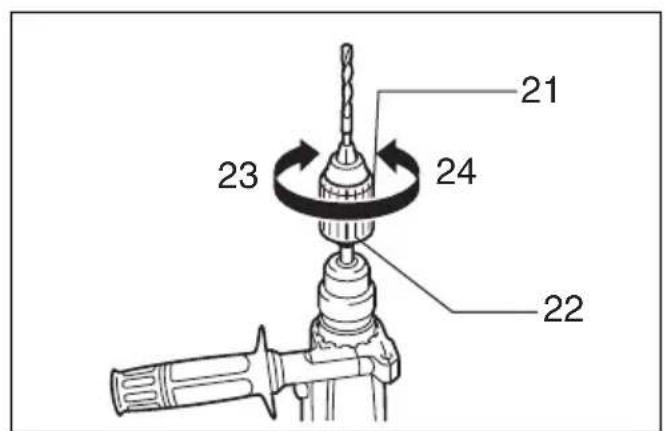
| 4 | Protrusions | 12 | Switch trigger | 20 Keyless drill chuck | |||||||
| 5 | Loosen | 13 | Lock button | 21 Sleeve | |||||||
| 6 | T | i | g | h | t | e | n | 14 | Lamp (HR2440F only) | 22 Ring | |
| 7 | Bit shank | 15 | Reversing switch lever | 23 Tighten | |||||||
| 8 | B | i | t | g | r | e | a | s | d | 6 Action mode changing knob | 24 Loosen |
SPECIFICATIONS
Model HR2440/HR2440X/HR2440F HR2441 HR2442
Capacities
Concrete
Tungsten-carbide tipped bit. 24mm 24mm 24mm
Core bit 54mm 54mm 54mm
Diamond core bit (dry type) 65mm 65mm 65mm
Wood
Steel 13mm
No load speed (^-1) 0-1,100
Blows per minute 0-4,500
Overall length 352 mm
Net weight. 2.3 kg
32 mm
13mm 13mm
0-1,100 1,100
0-4,500 4,500
352mm 352mm
2.3kg 2.3kg
- Due to our continuing program of research and development, the specifications herein are subject to change without notice.
Note: Specifications may differ from country to country.
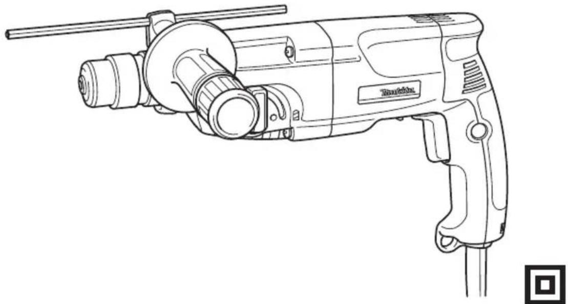
Intended use
The tool is intended for hammer drilling and drilling in brick, concrete and stone. It is also suitable for drilling without impact in wood, metal, ceramic and plastic.
Power supply
The tool should be connected only to a power supply of the same voltage as indicated on the nameplate, and can only be operated on single-phase AC supply. They are double-insulated in accordance with European Standard and can, therefore, also be used from sockets without earth wire.
Safety hints
For your own safety, please refer to the enclosed safety instructions.
ADDITIONAL SAFETY RULES
ENB010-1
- Hold tools by insulated gripping surfaces when performing an operation where the cutting tool may contact hidden wiring or its own cord. Contact with a "live" wire will make exposed metal parts of the tool "live" and shock the operator.
-
Wear ear protectors when using the tool for extended periods. Prolonged exposure to high intensity noise can cause hearing loss.
-
Wear a hard hat (safety helmet), safety glasses and/or face shield. It is also highly recommended that you wear a dust mask, and thickly padded gloves.
- Be sure the bit is secured in place before operation.
- Under normal operation, the tool is designed to produce vibration. The screws can come loose easily, causing a breakdown or accident. Check tightness of screws carefully before operation.
- In cold weather or when the tool has not been used for a long time, let the tool warm up for a while by operating it under no load. This will loosen up the lubrication. Without proper warm-up, hammering operation is difficult.
- Always be sure you have a firm footing. Be sure no one is below when using the tool in high locations.
- Hold the tool firmly with both hands.
- Keep hands away from moving parts.
- Do not leave the tool running. Operate the tool only when hand-held.
- Do not point the tool at any one in the area when operating. The bit could fly out and injure someone seriously.
- Do not touch the bit or parts close to the bit immediately after operation; they may be extremely hot and could burn your skin.
SAVE THESE INSTRUCTIONS.
OPERATING INSTRUCTIONS
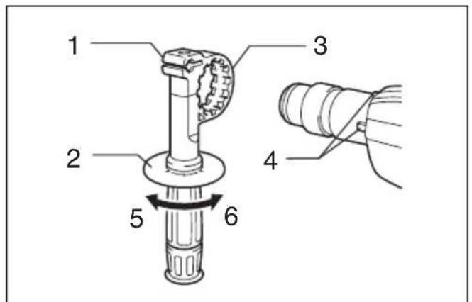
Side grip (auxiliary handle) (Fig. 1)
Always use the side grip to ensure operating safety. Install the side grip so that the teeth on the grip fit in between the protrusions on the tool barrel. Then tighten the grip by turning clockwise at the desired position. It may be swung 360^ so as to be secured at any position.
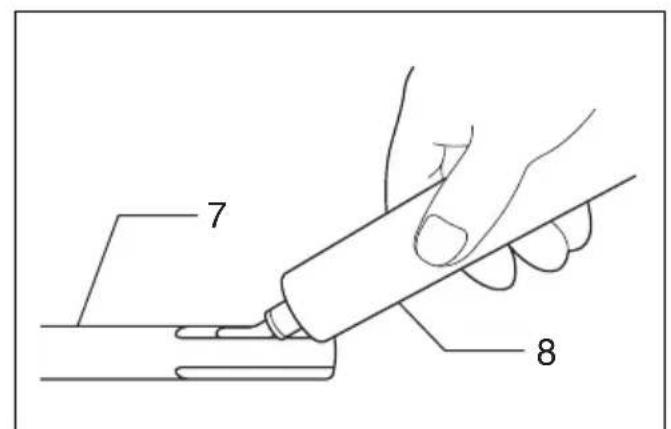
Installing or removing the bit
CAUTION:
Always be sure that the tool is switched off and unplugged before installing or removing the bit.
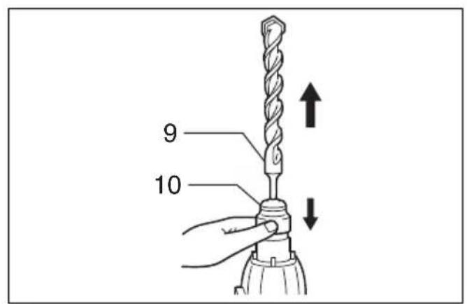
Clean the bit shank and apply bit grease before installing the bit. (Fig. 2)
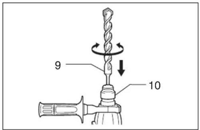
Insert the bit into the tool. Turn the bit and push it in until it engages. (Fig. 3)
After installing, always make sure that the bit is securely held in place by trying to pull it out.
To remove the bit, pull the chuck cover down all the way and pull the bit out. (Fig. 4)
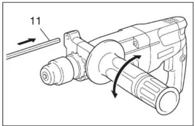
Depth gauge (Fig. 5)
The depth gauge is convenient for drilling holes of uniform depth. Loosen the side grip and insert the depth gauge into the hole in the side grip. Adjust the depth gauge to the desired depth and tighten the side grip.
NOTE:
The depth gauge cannot be used at the position where the depth gauge strikes against the gear housing.
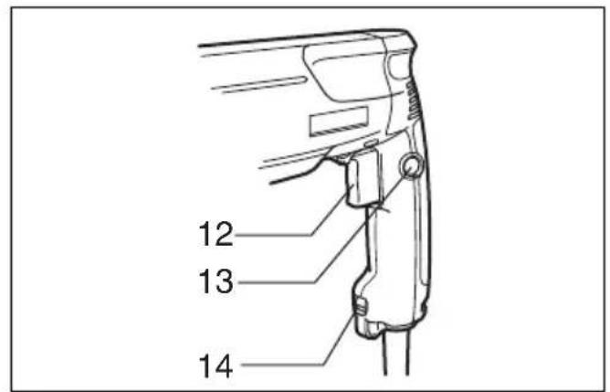
Switch action (Fig. 6)
CAUTION:
Before plugging in the tool, always check to see that the switch trigger actuates properly and returns to the "OFF" position when released.
For Model HR2440, HR2440X, HR2440F and HR2441
To start the tool, simply pull the switch trigger. Tool speed is increased by increasing pressure on the switch trigger. Release the switch trigger to stop. For continuous operation, pull the switch trigger and then push in the lock button. To stop the tool from the locked position, pull the switch trigger fully, then release it.
For Model HR2442
To start the tool, simply pull the switch trigger. Release the switch trigger to stop. For continuous operation, pull the switch trigger and then push in the lock button. To stop the tool from the locked position, pull the switch trigger fully, then release it.
Lighting up the lamps (Fig. 6)
For Model HR2440F
CAUTION:
Do not look in the light or see the source of light directly.
To turn on the lamp, pull the trigger. Release the trigger to turn it off.
NOTE:
Use a dry cloth to wipe the dirt off the lens of lamp. Be careful not to scratch the lens of lamp, or it may lower the illumination.
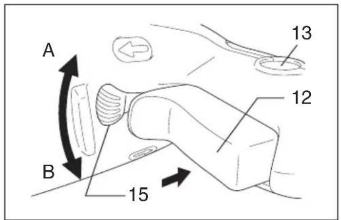
Reversing switch action (Fig. 7)
For Model HR2440, HR2440X, HR2440F
This tool has a reversing switch to change the direction of rotation. Move the reversing switch lever to the position (A side) for clockwise rotation or to the position (B side) for counterclockwise rotation.
CAUTION:
- Always check the direction of rotation before operation.
- Use the reversing switch only after the tool comes to a complete stop. Changing the direction of rotation before the tool stops may damage the tool.
- When you operate the tool in counterclockwise rotation, the switch trigger is pulled only halfway and the tool runs at half speed. For counterclockwise rotation, you cannot push in the lock button.
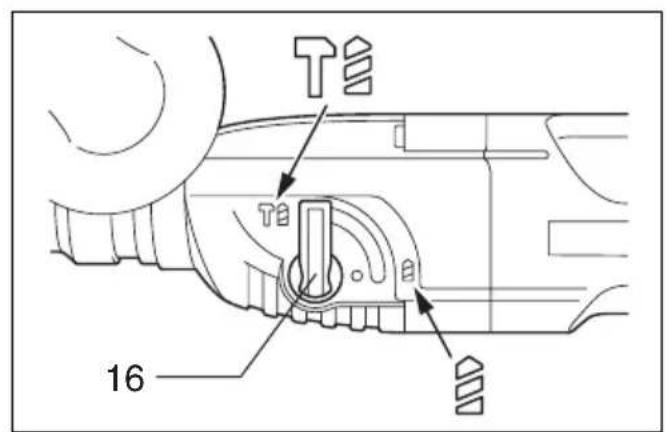
Selection action mode (Fig. 8)
This tool employs an action mode changing knob. Select one of the two modes suitable for your work needs by using this knob. For rotation only, turn the knob so that the arrow on the knob points toward the symbol on the tool body. For rotation with hammering, turn the knob so that the arrow on the knob points toward the symbol on the tool body.
CAUTION:
- Always set the knob fully to your desired mode symbol. If you operate the tool with the knob positioned halfway between the mode symbols, the tool may be damaged.
- Use the knob after the tool comes to a complete stop.
Torque limiter
The torque limiter will actuate when a certain torque level is reached. The motor will disengage from the output shaft. When this happens, the bit will stop turning.
CAUTION:
- As soon as the torque limiter actuates, switch off the tool immediately. This will help prevent premature wear of the tool.
- Hole saws cannot be used with this tool. They tend to pinch or catch easily in the hole. This will cause the torque limiter to actuate too frequently.
Hammer drilling operation
Position the bit at the desired location for the hole, then pull the trigger.
Do not force the tool. Light pressure gives best results. Keep the tool in position and prevent it from slipping away from the hole.
Do not apply more pressure when the hole becomes clogged with chips or particles. Instead, run the tool at an idle, then remove the bit partially from the hole. By repeating this several times, the hole will be cleaned out and normal drilling may be resumed.
CAUTION:
There is tremendous and sudden twisting force exerted on the tool/bit at the time of hole breakthrough, when the hole becomes clogged with chips and particles, or when striking reinforcing rods embedded in the concrete. Always use the side grip (auxiliary handle) and firmly hold the tool by both side grip and switch handle during operations. Failure to do so may result in the loss of control of the tool and potentially severe injury.
Bit grease
Coat the bit shank head beforehand with a small amount of bit grease (about 0.5 - 1g
This chuck lubrication assures smooth action and longer service life.
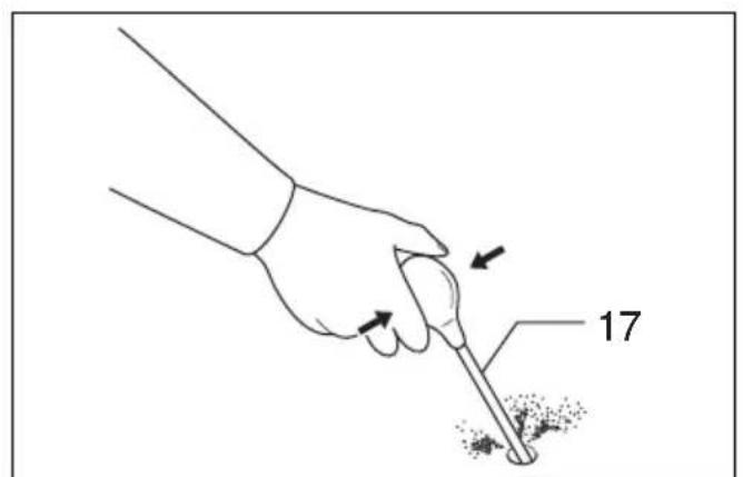
Blow-out bulb (Fig. 9)
Use the blow-out bulb to clean out the hold.
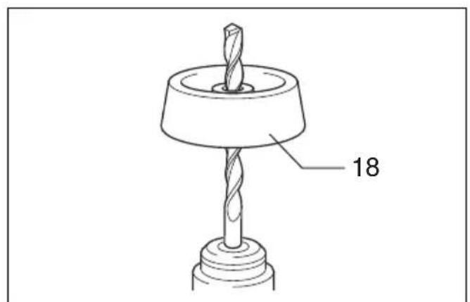
Dust cup (Fig. 10)
Use the dust cup to prevent dust from falling over the tool and on yourself when performing overhead drilling operations. Attach the dust cup to the bit as shown in Fig. 10. The size of bits which the dust cup can be attached to is as follows.
| Bit diameter (mm) | |
| Dust cup 5 6 - 14.5 | |
| Dust cup 9 12 - 16 |
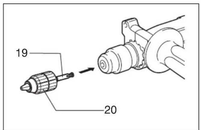
Drilling in wood or metal (Fig. 11 and 12)
Use the optional drill chuck assembly (standard equipment for Model HR2440X). When installing it, refer to "Installing or removing drill bit" described on the previous page.
Hold the ring and turn the sleeve counterclockwise to open the chuck jaws. Place the bit in the chuck as far as it will go. Hold the ring firmly and turn the sleeve clockwise to tighten the chuck.
To remove the bit, hold the ring and turn the sleeve counterclockwise. Set the action mode changing knob to "rotation only". You can drill up to 13mm diameter in metal and up to 32mm diameter in wood.
CAUTION:
- Never use "rotation with hammering" when the drill chuck assembly is installed on the tool. The drill chuck assembly may be damaged.
Also, the drill chuck will come off when reversing the tool. (For Model HR2440, HR2440X, HR2440F)
- Pressing excessively on the tool will not speed up the drilling. In fact, this excessive pressure will only serve to damage the tip of your bit, decrease the tool performance and shorten the service life of the tool.
- There is a tremendous twisting force exerted on the tool/bit at the time of hole breakthrough. Hold the tool firmly and exert care when the bit begins to break through the workpiece.
- A stuck bit can be removed simply by setting the reversing switch to reverse rotation in order to back out. However, the tool may back out abruptly if you do not hold it firmly.
Always secure small workpieces in a vise or similar hold-down device. - When performing diamond core drilling operation, always set the change lever to the < position to use "rotation only" action. If performing diamond core drilling operation with "rotation with hammering" action, the diamond core bit may be damaged.
MAINTENANCE
CAUTION:
Always be sure that the tool is switched off and unplugged before carrying out any work on the tool.
To maintain product safety and reliability, repairs, maintenance or adjustment should be carried out by a Makita Authorized Service Center.
FRANÇAIS
Descriptif
20 Schlüsselloses Bohrfutter
5 L öse n
Model HR2440/HR2440X/HR2440F HR2441 HR2442
Bohrleistung
Beton
HM-bestuckter Bohrer 24 mm 24 mm 24 mm
Bohrkrone. 54 mm 54 mm 54 mm
Diamantkernbohrer (Trockentyp).... 65 mm 65 mm 65 mm
Holz
.
32
mm
Stahl
13
mm
Modelli HR2440, HR2440X, HR2440F
Para HR2440, HR2440X, HR2440F
Acender as Iampadas (Fig. 6)
Para HR2440F
PRECAUÇA:
Model HR2440/HR2440X/HR2440F HR2441 HR2442
| Kapacitet | |||
| Beton | |||
| Bor medHardmetalspids.........24 mm 24 mm 24 mm | |||
| Kernebor.........54 mm 54 mm 54 mm | |||
| Diamantkernebor (tor type).........65 mm 65 mm 65 mm | |||
| Træ | 32 | mm | |
| Stål | 13 | mm | |
| Omdrejninger (min-1)...0-1100 | 0-1100 | 1100 | |
| Slagantal (min)...0-4500 | 0-4500 | 4500 | |
| Laṅnge | 352 | mm | |
| Netto vægt.......2,3kg | 2,3kg | 2,3kg | |
For HR2440, HR2440X, HR2440F
Denne maskine er forsynet med en omdrejningsvaelger til at aendre omdrejningsretningen. Flyt omdrejningsvaelgeren til positionen (A side) for rotation med uret, ellter til positionen (B side) for rotation mod uret.
FORSIGTIG:
Model HR2440/HR2440X/HR2440F HR2441 HR2442
Kapacitet
Betong
Borr med hardmetallspets. 24 mm 24 mm 24 mm
Kronborr. 54 mm 54 mm 54 mm
Kronborr med diamantspets (torr typ).... 65 mm 65 mm 65 mm
Trä 32 mm 32
Stål 13 mm
Tomgangsvarvtal (^-1) 0
Antal slag. 0-4500 0-4500 4500
Total langd 352 mm
Nettovikt. 2,3 kg 2,3
For HR2440, HR2440X, HR2440F
Gjelder HR2440, HR2440X, HR2440F
Malli HR2440/HR2440X/HR2440F HR2441 HR2442
Suorituskyky
Betoni
Volframikarbidikärkinen tera. 24 mm 24 mm 24 mm
Keernakaira 54 mm 54 mm 54 mm
Tia HR2440, HR2440X, HR2440F kai HR2441
Ia va Eekivnoi to nXavnua TpaBnxTn OkaVdaI
diakoTTnc. H taxutnta Tou nXavmaTOc auAveTai
ue auEonTnC niocn otN oKavdaIaN diakoTTnc. Ia
va Otapatnoe ELEUthetaPwTe TN OkaVdaI
diakoTTnc. Ia ouvexn LEIToupyia, TpaBnxtE Tn
OkaVdaI NIAKOITTNC KAI eTa ONpWxTE MEOA TO
koumna aOphiAlionc. Ia va OtaatnoeTo nXavna
anotn Theon aoFaiianc, TpaBnxTn OkaVdaI
diakoTTnc PAnpwcs kai eT a apnote tn.
T1a HR2442
Ia va Ekvnoi To unxavma TpaBnxt E n OkaVdaN diakoTnc. Ia va otapatnoe ELEuEepwote Tn qavdaan diakoTnc. Ia ouvx n Aetoupyia, TpaBnxt E n Okavdaan diakoTnc kai e Ta onpoxte eaa to Koumi aoffaianc. Ia va otapatnoe T o unxavma ano tn th eon aaffalionc, TpaBnxt Tn okavdaan diakoTnc nppw cai e Ta afnoTe tn.
AvaμaTwvλaπωv(Eik.6)
Tia HR2440F
PPOEOXH:
Mn kuttate to oute va tv nyn c a n e u i a c.
Ia va avapeTe Tn Ama, TpaBexTe Tn Okavdaan. EeUthetaTn Okavdaan yia va tn oBnoTe.
ZHMEIΩΣH:
XpnoionoieE eva oteyv oopa yia va okouniTe toupunous ano to fako tnc laumac. IpooexeTva un ypatouovioeTe to fako tnC laumac, diaopoptika 0e1w0ei o wtiouoc.
AikonncavioatpOoNc (Eik.7)
T1a HR2440, HR2440X, HR2440F
AutoTo epyaIeio exei eviaikontnnaviotpophi n yia va aalaczI tnv dieuuvon nepiotpophi n. Metakiveiote To koumi Tou iakontnnepiotpophi n otn theo (A pua) ia oopn np np np np np np np np np np np np np np np np np np np np np np np np np np np np np np np np np np np np np np np np np np np np np np np np np np np np np np np np np np np np np np np npnpnpnpnpnpnpnpnpnpnpnpnpnpnpnpnpnpnpnpnpnpnpnpnpnpnpnpnpnpnpnpnpnpnpnpnpnpnpnpnpnpnpnpnpnpnpnpnpnpnpnpnpnpnpnpnpnpnpnpnpnpnpnpnpnpnpnpnpnpnpnpnpnpnpnpnpnpnpnpnpnpnpnpnpnpnpnpnpnpnpnpnpnpnpnpnpnpnpnpnp
PPOEOXH:
These accessories or attachments are recommended for use with your Makita tool specified in this manual. The use of any other accessories or attachments might present a risk of injury to persons. The accessories or attachments should be used only in the proper and intended manner.
F ACCESSORIES
ATTENTION:
EC-DECLARATION OF CONFORMITY
We declare under our sole responsibility that this product is in compliance with the following standards or standardized documents,
HD400, EN50144, EN55014, EN61000 in accordance with Council Directives, 73/23/EEC, 89/336/EEC and 98/37/EC.
FRANÇAISE
DECLARATION DE CONFORMITE CE
HD400, EN50144, EN55014, EN61000.
ITALIANO
Michigan Drive, Tongwell, Milton Keynes,
Bucks MK15 8JD, ENGLAND
PORTUGUES
DECLARACAO DE CONFORMIDADE DA CE
Declaramos sob inteira responsabilité que este produit obedece as seguintes normas ou documents normalizados,
HD400, EN50144, EN55014, EN61000 de accordo com as direcitas 73/23/CEE, 89/336/CEE e 98/37/CE do Conselho.
DANSK
EU-DEKLARATION OM KONFORMITET
Michigan Drive, Tongwell, Milton Keynes,
Bucks MK15 8JD, ENGLAND
ENGLISH
Noise and Vibration
The typical A-weighted noise levels are sound pressure level: 87 dB (A) sound power level: 100 dB (A)
- Wear ear protection.
The typical weighted root mean square acceleration value is 9.0m / s^2
FRANÇAISE
Bruit et vibrations
-Benyth horselvern.-
