GWS 18V125C Professional - Grinder BOSCH - Free user manual and instructions
Find the device manual for free GWS 18V125C Professional BOSCH in PDF.
Download the instructions for your Grinder in PDF format for free! Find your manual GWS 18V125C Professional - BOSCH and take your electronic device back in hand. On this page are published all the documents necessary for the use of your device. GWS 18V125C Professional by BOSCH.
USER MANUAL GWS 18V125C Professional BOSCH
Bluetooth®4.2 (Low Energy)
Bluetooth®4.2 (Low Energy)
Bluetooth®4.2 (Low Energy)
Bluetooth®4.2 (Low Energy)
Bluetooth®4.2 (Low Energy)
, a fault may occur in other devices and systems, aero- planes and medical devices (e.g. pacemakers, hearing aids). Also, damage to people and animals in the im- mediate vicinity cannot be completely excluded. Do not use the power tool with Bluetooth
in the vicinity of medical devices, petrol stations, chemical plants, areas with a potentially explosive atmosphere or in blasting areas. Do not use the power tool with Bluetooth
in aircraft. Avoid using the product near your body for extended periods. The Bluetooth® word mark and logos are registered trade- marks owned by Bluetooth SIG, Inc. and any use of such marks by Robert Bosch Power Tools GmbH is under li- cense. Product Description and Specifications Read all the safety and general instructions. Failure to observe the safety and general in- structions may result in electric shock, fire and/or serious injury. Please observe the illustrations at the beginning of this oper- ating manual. Intended use The power tool is intended for cutting, roughing and brush- ing metal and stone materials without the use of water. A special protective guard for cutting must be used when cutting bonded abrasives. Sufficient dust extraction must be provided when cutting stone. With approved abrasive tools, the power tool can be used for sanding with sanding discs. With the Bluetooth
Low Energy Module GCY30-4 inserted, power tool data and settings can be transferred between the power tool and a mobile device by means of Bluetooth
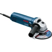
wire- less technology. Product Features The numbering of the product features refers to the diagram of the power tool on the graphics page. (1) Unlocking lever for protective guard (2) Direction of rotation arrow on housing (3) Spindle lock button (4) LED work light (GWS 18V-10 SC) (5) User interface (6) On/off switch (7) Bluetooth module cover (8) Battery
(9) Battery release button
(10) Auxiliary handle (insulated gripping surface) (11) Extraction guard for grinding
Bosch Power Tools 1 609 92A 6YN | (28.07.2021)24 | English (12) Protective guard for grinding (13) Mounting flange with O‑ring (14) Grinding disc (15) Quick-clamping nut with bar (16) Carbide grinding head
(17) Protective guard for cutting
(19) Handle (insulated gripping surface) (20) Grinding spindle (21) Hand guard
(22) Rubber sanding pad
(26) Diamond core bit
(27) Extraction guard for cutting with cutting guides
(28) Diamond cutting disc
Accessories shown or described are not included with the product as standard. You can find the complete selection of accessories in our accessories range. Technical Data Angle grinder GWS 18V-10 C GWS 18V-10 C GWS 18V-10 C Article number 3601JG30.. 3601JG32.. 3601JG31.. Rated voltage V= 18 18 18 Rated speed
Max. grinding disc diameter mm 100 115 125 Grinding spindle thread M 10 M 14 M 14 Max. thread length of grinding spindle mm 22 22 22 Kickback stop ● ● ● Restart protection ● ● ● Run-out brake ● ● ● Speed preselection – – – Weight according to EPTA-Procedure01:2014
– with low-vibration auxiliary handle kg 2.3–3.3 2.3–3.3 2.3–3.3 – with standard auxiliary handle kg 2.2–3.2 2.2–3.2 2.2–3.2 Recommended ambient temperature during charging °C 0to+35 0to+35 0to+35 Permitted ambient temperature during operation
Bluetooth®4.2 (Low Energy)
Bluetooth®4.2 (Low Energy)
m 30 30 30 A) Rated speed in accordance with EN 60745-2-3 B) Depends on battery in use C) Limited performance at temperatures <0°C D) The mobile terminal devices must be compatible with Bluetooth
Low Energy devices (version 4.2) and support the Generic Access Profile (GAP). E) The signal range may vary greatly depending on external conditions, including the receiving device used. The Bluetooth® range may be signi- ficantly weaker inside closed rooms and through metallic barriers (e.g. walls, shelving units, cases, etc.). Angle grinder GWS 18V-10 SC GWS 18V-10 SC GWS 18V-10 SC GWS 18V-10 SC Article number 3601JG33.. 3601JG36.. 3601JG34.. 3601JG35.. Rated voltage V= 18 18 18 18 Rated speed
4500–9000 4500–9000 4500–9000 4000–7500 Max. grinding disc diameter mm 100 115 125 150 Grinding spindle thread M 10 M 14 M 14 M 14 Max. thread length of grinding spindle mm 22 22 22 22 Kickback stop ● ● ● ● Restart protection ● ● ● ● Run-out brake ● ● ● ● Speed preselection ● ● ● ● Weight according to EPTA-Procedure01:2014
– with low-vibration auxiliary handle kg 2.3–3.3 2.3–3.3 2.3–3.3 2.3–3.3 – with standard auxiliary handle kg 2.2–3.2 2.2–3.2 2.2–3.2 2.2–3.2 Recommended ambient temperature during charging °C 0to+35 0to+35 0to+35 0to+35 Permitted ambient temperature during operation
Bluetooth®4.2 (Low Energy)
Bluetooth®4.2 (Low Energy)
Bluetooth®4.2 (Low Energy)
m 30 30 30 30 A) Rated speed in accordance with EN 60745-2-3 B) Depends on battery in use C) Limited performance at temperatures <0°C D) The mobile terminal devices must be compatible with Bluetooth
Low Energy devices (version 4.2) and support the Generic Access Profile (GAP). E) The signal range may vary greatly depending on external conditions, including the receiving device used. The Bluetooth® range may be signi- ficantly weaker inside closed rooms and through metallic barriers (e.g. walls, shelving units, cases, etc.). Noise/Vibration Information GWS 18V-10 C GWS 18V-10 C GWS 18V-10 C 3601JG30.. 3601JG32.. 3601JG31.. Bosch Power Tools 1 609 92A 6YN | (28.07.2021)26 | English GWS 18V-10 C GWS 18V-10 C GWS 18V-10 C Noise emission values determined according toEN60745-2-3. Typically, the A-weighted noise level of the power tool is Sound pressure level Sound power level UncertaintyK Wear hearing protection! dB(A) dB(A)
(triax vector sum) and uncertaintyK determined according toEN60745-2-3: Surface grinding:
(triax vector sum) and uncertaintyK determined according toEN60745-2-3: Surface grinding:
The vibration level given in these instructions has been measured in accordance with a standardised measuring pro- cedure and may be used to compare power tools. It can also be used for a preliminary estimation of exposure to vibra- tion. The stated vibration level applies to the main applications of the power tool. However, if the power tool is used for differ- ent applications, with different application tools or poorly maintained, the vibration level may differ. This can signific- antly increase the exposure to vibration over the total work- ing period. To estimate the exposure to vibration accurately, the times when the tool is switched off or when it is running but not ac- tually being used should also be taken into account. This can significantly reduce the exposure to vibration over the total working period. Implement additional safety measures to protect the oper- ator from the effects of vibration, such as servicing the power tool and application tools, keeping the hands warm, and organising workflows correctly. Fitting Inserting the Bluetooth
Low Energy ModuleGCY30-4 is avail- able as an accessory with GWS 18V-10 C power tools; it is included in the scope of delivery for GWS 18V-10 SC power tools. Read the corresponding operating instructions for informa- tion about the Bluetooth® Low Energy ModuleGCY30-4. 1 609 92A 6YN | (28.07.2021) Bosch Power ToolsEnglish | 27 Battery Charging u Use only the chargers listed in the technical data. Only these chargers are matched to the lithium-ion battery of your power tool. Note: The battery is supplied partially charged. To ensure full battery capacity, fully charge the battery in the charger before using your power tool for the first time. The lithium-ion battery can be charged at any time without reducing its service life. Interrupting the charging process does not damage the battery. The lithium-ion battery is protected against deep discharge by the "Electronic Cell Protection (ECP)". When the battery is discharged, the power tool is switched off by means of a protective circuit: The application tool no longer rotates. u Do not continue to press the On/Off switch after the power tool has automatically switched off. The battery can be damaged. Follow the instructions on correct disposal. Removing the Battery The battery (8) is equipped with two locking levels to pre- vent the battery from falling out if the battery release button (9) is pressed unintentionally. As long as the battery is inser- ted in the power tool, it is held in position by means of a spring. To remove the battery (8), press the release button (9) and pull the battery out of the power tool. Do not use force to do this. Battery charge indicator The green LEDs on the battery charge indicator indicate the state of charge of the battery. For safety reasons, it is only possible to check the state of charge when the power tool is not in operation. Press the button for the battery charge indicator or to show the state of charge. This is also possible when the bat- tery is removed. If no LED lights up after pressing the button for the battery charge indicator, then the battery is defective and must be replaced. Note: The state of charge of the battery is also displayed on the user interface (5) (see "User interface (see figure B)", page30). Battery model GBA 18V... LEDs Capacity 3× continuous green light 60−100% 2× continuous green light 30−60% 1× continuous green light 5−30% 1× flashing green light 0−5% Battery model ProCORE18V... LEDs Capacity 5× continuous green light 80−100% 4× continuous green light 60−80% 3× continuous green light 40−60% 2× continuous green light 20−40% 1× continuous green light 5−20% 1× flashing green light 0−5% Fitting Protective Equipment u Remove the battery from the power tool before carry- ing out work on the power tool (e.g. maintenance, changing tool, etc.). The battery should also be re- moved for transport and storage. There is risk of injury from unintentionally pressing the on/off switch. Note: If the grinding disc breaks during operation or the holding fixtures on the protective guard/power tool become damaged, the power tool must be sent to the after-sales ser- vice immediately; see the "After-Sales Service and Applica- tion Service" section for addresses. Protective guard for grinding Place the protective guard (12) onto the holder on the power tool until the coding cams of the protective guard are aligned with the holder. When doing so, press and hold the unlocking lever (1). Press the protective guard (12) onto the spindle collar until the shoulder of the pro- tective guard is sitting on the flange of the power tool and rotate the protective guard until it audibly clicks into place. Adjust the position of the protective guard (12) to meet the requirements of the operation. To do this, push the unlock- ing lever (1) upward and rotate the protective guard (12) into the required position. u Always position the protective guard(12) such that the two cams on the unlocking lever(1) engage in the corresponding openings on the protective guard(12). u Adjust the protective guard (12) such that sparking in the direction of the operator is prevented. u The protective guard (12) must only be adjustable while the unlocking lever (1) is actuated. Otherwise, the power tool must not be used any more under any circumstances and must be sent to the after-sales ser- vice. Bosch Power Tools 1 609 92A 6YN | (28.07.2021)28 | English Note: The coding cams on the protective guard (12) ensure that only a protective guard that is suitable for the power tool can be fitted. Protective guard for cutting u Always use the protective guard for cutting (17) when cutting bonded abrasives. u Provide sufficient dust extraction when cutting stone. The protective guard for cutting (17) is fitted in the same way as the protective guard for grinding (12). Extraction guard for sanding The extraction guard (11) can be used to minimise dust when sanding paint, varnish and plastics in conjunction with the carbide grinding head (16). The extraction guard (11) is not suitable for working metals. A suitable Bosch vacuum cleaner can be connected to the extraction guard (11). The extraction guard (11) is mounted in the same manner as the protective guard (12). The brush collar can be replaced. Extraction guard for cutting with a guide block The extraction guard for cutting with a guide block (27) is fit- ted in the same way as the protective guard for grinding (12). Side handle u Do not operate your power tool without the side handle (10). u Do not continue to use the power tool if the auxiliary handle is damaged. Do not make any alterations to the auxiliary handle. Screw the side handle (10) on the left or right of the ma- chine head depending on how your are working. Low-vibration auxiliary handle The low-vibration auxiliary handle reduces vibration, enabling the tool to be used safely and more comfort- ably. u Do not make any alterations of any kind to the auxili- ary handle. Do not continue to use a damaged auxiliary handle. Hand guard u Always fit the hand guard (21) when working with the rubber sanding plate (22) or with the cup brush/disc brush/flap disc. Attach the hand guard (21) to the side handle (10). Fitting the abrasive tools u Remove the battery from the power tool before carry- ing out work on the power tool (e.g. maintenance, changing tool, etc.). The battery should also be re- moved for transport and storage. There is risk of injury from unintentionally pressing the on/off switch. u Do not touch grinding and cutting discs until they have cooled down. The discs can become very hot while work- ing. Clean the grinding spindle (20) and all the parts to be fitted. Lock the grinding spindle with the spindle lock button (3) before clamping and releasing the abrasive tools. u Do not press the spindle lock button while the grind- ing spindle is moving. The power tool may become dam- aged if you do this. Grinding/Cutting Disc Pay attention to the dimensions of the abrasive tools. The diameter of the hole must match that of the hub flange. Do not use an adapter or reducer. When using diamond cutting discs, ensure that the arrow in- dicating the direction of rotation on the diamond cutting disc matches the direction of rotation of the power tool (see the direction of rotation arrow on the machine head). See the graphics page for fitting instructions. Use the quick-clamping nut (15) to secure the grinding/cut- ting disc without the need for additional tools. Only use the quick-clamping nut (15) for grinding/cutting discs up to a maximum diameter of 150mm. u The quick-clamping nut (15) may be used only for grinding or cutting discs. u Only use quick-clamping nuts (15) that are in good working order and not damaged. u When screwing on, make sure that the printed side of the quick-clamping nut (15) is not facing the grinding disc. u Always secure a grinding/cutting disc using only the quick-clamping nut (15) supplied. Press the spindle lock but- ton (3) to lock the grinding spindle. To tighten the quick-clamping nut (15), fold up the bar and turn the quick-clamping nut firmly clockwise. Then fold down the bar to secure the quick- clamping nut. It is not suf- ficient to tighten the disc along the edge. 1 609 92A 6YN | (28.07.2021) Bosch Power ToolsEnglish | 29 Quick-clamping nuts (15) that are properly secured and not damaged can be re- moved by hand. To do this, fold up the bar and turn the quick-clamping nut firmly anticlockwise. If the quick- clamping nut is stuck, do not attempt to loosen it with a tool – always use a two- pin spanner. After fitting the hub flange and the grinding/cutting disc, the free thread length of the grinding spindle must be at least 4mm. Ensure that the abrasive tool is firmly seated, so that it does not twist away from the spindle in the runout of the power tool. A plastic part (O-ring) is fitted around the cent- ring collar in the hub flange (13). If the O-ring is missing or damaged, the hub flange (13) must be replaced before operation can re- sume. u After fitting the abrasive tool, check that the abrasive tool is fitted correctly and can turn freely before switching on the power tool. Make sure that the abras- ive tool does not brush against the protective guard or other parts. Flap disc u Always fit the hand guard (21) when working with the flap disc. Rubber Sanding Pad u Always fit the hand guard (21) when working with the rubber sanding pad (22). See the graphics page for fitting instructions. Slide the rubber sanding pad (22) onto the grinding spindle (20). Press the sanding sheet (23) firmly onto the underside of the rubber sanding pad (22). Screw on the round nut (24) and tighten with a two-pin spanner. Cup brush/disc brush u Always fit the hand guard (21) when working with the cup brush or disc brush. See the graphics page for fitting instructions. The cup brush/disc brush must be screwed onto the grinding spindle until it rests firmly against the grinding spindle flange at the end of the grinding spindle thread. Tighten the cup brush/disc brush with an open-ended spanner. Carbide Grinding Head u A grinding head may be used only with a suitable pro- tective guard. Approved Abrasive Tools You can use all the abrasive tools mentioned in these operat- ing instructions. The permissible speed [min
] or the circumferential speed [m/s] of the abrasive tools used must at least match the val- ues given in the table. It is therefore important to observe the permissible rota- tional/circumferential speed on the label of the abrasive tool. max. [mm] [mm] D b d [min
u Remove the battery from the power tool before carry- ing out work on the power tool (e.g. maintenance, changing tool, etc.). The battery should also be re- moved for transport and storage. There is risk of injury from unintentionally pressing the on/off switch. The machine head can be rotated in 90° increments. In this way, the on/off switch can be brought into a more favourable handling position for particular ap- plications, e.g. for left- handed tool users. Completely unscrew the four screws. Rotate the ma- chine head carefully, without removing it from the hous- Bosch Power Tools 1 609 92A 6YN | (28.07.2021)30 | English ing, into the new position. Screw in and retighten the four screws. Dust/Chip Extraction Dust from materials such as lead-containing coatings, some wood types, minerals and metal can be harmful to one’s health. Touching or breathing-in the dust can cause allergic reactions and/or lead to respiratory infections of the user or bystanders. Certain dust, such as oak or beech dust, is considered carci- nogenic, especially in connection with wood-treatment ad- ditives (chromate, wood preservative). Materials containing asbestos may only be worked by specialists. – Provide for good ventilation of the working place. – It is recommended to wear a P2 filter-class respirator. Observe the relevant regulations in your country for the ma- terials to be worked. u Avoid dust accumulation at the workplace. Dust can easily ignite. Operation Starting Operation Inserting the battery Push the charged battery (8) into the base of the power tool from the front until the battery is securely locked. Switching on/off To start the power tool, push the on/off switch (6) forward. To lock the on/off switch (6) in position, push the on/off switch (6) forward and down until it clicks into place. To switch off the power tool, release the on/off switch (6); or, if the switch is locked, briefly push the on/off switch (6) backward and down and then release it. u Always check abrasive tools before using them. The abrasive tool must be fitted properly and be able to move freely. Carry out a test run for at least one minute with no load. Do not use abrasive tools that are damaged, run untrue or vibrate during use. Damaged abrasive tools can burst apart and cause injuries. Kickback stop If there is a sudden kickback in the power tool, e.g. jamming in a separating cut, the power supply to the motor will be interrupted elec- tronically. The LED work light (4) then flashes white and the status indicator (32) flashes red. To restart the tool, set the on/off switch (6) to the off posi- tion and then switch the power tool on again. Restart protection The restart protection feature prevents the power tool from uncontrolled starting after the power supply to it has been interrupted. When restart protection is activated, the status indicator (32) flashes red. To restart the tool, set the on/off switch (6) to the off posi- tion and then switch the power tool on again. Impact shutdown The integrated impact shutdown switches the power tool off as soon as it hits the floor. The status indicator (32) then flashes red. To restart the tool, set the on/off switch (6) to the off position and then switch the power tool on again. User interface (see figure B) The user interface (5) is used to preselect the speed and to indicate the status of the power tool. Speed preselection
You can use the button for speed preselection (31) to preselect the required speed, even during operation. The information in the table below describes the recommended values. Material Application Application tool Speed preselection level
Metal Brushing, removing rust Cup brush 1 4500 4000 Stainless steel Grinding Fibre disc 2 6000 5500 Metal Rough grinding Grinding disc 3 9000 7500 Metal Cutting Grinding disc 3 9000 7500 Stone Cutting Diamond cutting disc and cutting guide (cutting stone is per- mitted only with a cutting guide)
The values specified for speed levels are guide values. 1 609 92A 6YN | (28.07.2021) Bosch Power ToolsEnglish | 31 u The rated speed of the accessory must be at least equal to the maximum speed marked on the power tool. Accessories running faster than their rated speed can break and fly apart. Status indications Battery charge indicator (user interface) (29) Meaning/cause Solution Green Battery charged – Yellow Battery almost empty Replace or charge battery soon Red Battery empty Replace or charge battery Overload protection indic- ator (33) Meaning/cause Solution Yellow Critical temperature has been reached (mo- tor, electronics, battery) Run the power tool at no load and allow it to cool down Red Power tool is overheated and will switch off Leave the power tool to cool down Power tool status indicator (32) Meaning/cause Solution Green Status OK – Yellow Critical temperature has been reached or bat- tery is almost empty Run the power tool at no load and allow it to cool down, or replace or charge the battery soon Illuminated red Power tool is overheated or battery is empty Allow the power tool to cool down, or replace or charge the battery Flashing red Kickback shutdown, restart protection or im- pact shutdown has been triggered Turn the power tool off and on again Flashing blue Power tool is connected to a mobile device or settings are being transferred
Connectivity functions In conjunction with the Bluetooth® Low Energy Module GCY30-4, the following connectivity functions are available for the power tool: – Registration and personalisation – Status check, output of warning messages – General information and settings – Management Read the corresponding operating instructions for informa- tion about the Bluetooth® Low Energy ModuleGCY30-4. Practical advice u The power tool with inserted Bluetooth
Bluetooth®4.2 (Low Energy)
Bluetooth®4.2 (Low Energy)
Bluetooth®4.2 (Low Energy)
Bluetooth®4.2 (Low Energy)
Bluetooth®4.2 (Low Energy)
(100/115/125mm) [tr/min]
Bluetooth® 4.2 (Low Energy)
Bluetooth® 4.2 (Low Energy)
Bluetooth® 4.2 (Low Energy)
Bluetooth® 4.2 (Low Energy)
Bluetooth® 4.2 (Low Energy)
Bluetooth®4.2 (Low Energy)
Bluetooth®4.2 (Low Energy)
Bluetooth®4.2 (Low Energy)
Bluetooth®4.2 (Low Energy)
Bluetooth®4.2 (Low Energy)
6,0 1,5 6,0 1,5 6,0 1,5 Lixamento com disco:
Bluetooth® 4.2 (Low Energy)
Bluetooth® 4.2 (Low Energy)
Bluetooth® 4.2 (Low Energy)
Bluetooth® 4.2 (Low Energy)
Bluetooth® 4.2 (Low Energy)
Bluetooth®4.2 (Low Energy)
Bluetooth®4.2 (Low Energy)
Bluetooth®4.2 (Low Energy)
Bluetooth®4.2 (Low Energy)
Bluetooth®4.2 (Low Energy)
Bluetooth®4.2 (Low Energy)
Bluetooth®4.2 (Low Energy)
Bluetooth®4.2 (Low Energy)
Bluetooth®4.2 (Low Energy)
Bluetooth®4.2 (Low Energy)
Bluetooth®4.2 (Low Energy)
Bluetooth®4.2 (Low Energy)
Bluetooth®4.2 (Low Energy)
Bluetooth®4.2 (Low Energy)
Bluetooth®4.2 (Low Energy)
Bluetooth®4.2 (Low Energy)
Bluetooth®4.2 (Low Energy)
Bluetooth®4.2 (Low Energy)
Bluetooth®4.2 (Low Energy)
Bluetooth®4.2 (Low Energy)
Bluetooth®4.2 (Low Energy)
Bluetooth®4.2 (Low Energy)
Bluetooth®4.2 (Low Energy)
Bluetooth®4.2 (Low Energy)
Bluetooth®4.2 (Low Energy)
Bluetooth®4.2 (Low Energy)
Bluetooth®4.2 (Low Energy)
Bluetooth®4.2 (Low Energy)
Bluetooth®4.2 (Low Energy)
Bluetooth®4.2 (Low Energy)
Bluetooth®4.2 (Low Energy)
Bluetooth®4.2 (Low Energy)
Bluetooth®4.2 (Low Energy)
Bluetooth®4.2 (Low Energy)
Bluetooth®4.2 (Low Energy)
Bluetooth® 4.2 (Low Energy)
Bluetooth® 4.2 (Low Energy)
Bluetooth® 4.2 (Low Energy)
Bluetooth® 4.2 (Low Energy)
Bluetooth® 4.2 (Low Energy)
Bluetooth®4.2 (Low Energy)
Bluetooth®4.2 (Low Energy)
Bluetooth®4.2 (Low Energy)
Bluetooth®4.2 (Low Energy)
Bluetooth®4.2 (Low Energy)
(100/115/125mm) [ot/min]
Bluetooth®4.2 (Low Energy)
Bluetooth®4.2 (Low Energy)
Bluetooth®4.2 (Low Energy)
Bluetooth®4.2 (Low Energy)
Bluetooth®4.2 (Low Energy)
Bluetooth®4.2 (Low Energy)
Bluetooth®4.2 (Low Energy)
Bluetooth®4.2 (Low Energy)
Bluetooth®4.2 (Low Energy)
Bluetooth®4.2 (Low Energy)
Bluetooth®4.2 (Low Energy)
Bluetooth®4.2 (Low Energy)
Bluetooth®4.2 (Low Energy)
Bluetooth®4.2 (Low Energy)
Bluetooth®4.2 (Low Energy)
Bluetooth®4.2 (Low Energy)
Bluetooth®4.2 (Low Energy)
Bluetooth®4.2 (Low Energy)
Bluetooth®4.2 (Low Energy)
Bluetooth®4.2 (Low Energy)
Bluetooth®4.2 (Low Energy)
Bluetooth®4.2 (Low Energy)
Bluetooth®4.2 (Low Energy)
Bluetooth®4.2 (Low Energy)
Bluetooth®4.2 (Low Energy)
(100/115/125mm) [rot/min]
Bluetooth®4.2 (Low Energy)
Bluetooth®4.2 (Low Energy)
Bluetooth®4.2 (Low Energy)
Bluetooth®4.2 (Low Energy)
Bluetooth®4.2 (Low Energy)
Bluetooth®4.2 (Low Energy)
Bluetooth®4.2 (Low Energy)
Bluetooth®4.2 (Low Energy)
Bluetooth®4.2 (Low Energy)
Bluetooth®4.2 (Low Energy)
www.bosch-pt.com/serviceaddresses
Bluetooth®4.2 (Low Energy)
Bluetooth®4.2 (Low Energy)
Bluetooth®4.2 (Low Energy)
Bluetooth®4.2 (Low Energy)
Bluetooth®4.2 (Low Energy)
Bluetooth®4.2 (Low Energy)
Bluetooth®4.2 (Low Energy)
Bluetooth®4.2 (Low Energy)
Bluetooth®4.2 (Low Energy)
Bluetooth®4.2 (Low Energy)
Bluetooth® 4.2 (Low Energy)
Bluetooth® 4.2 (Low Energy)
Bluetooth® 4.2 (Low Energy)
Bluetooth® 4.2 (Low Energy)
Bluetooth® 4.2 (Low Energy)
Bluetooth®4.2 (Low Energy)
Bluetooth®4.2 (Low Energy)
Bluetooth®4.2 (Low Energy)
Bluetooth®4.2 (Low Energy)
Bluetooth®4.2 (Low Energy)
6,0 1,5 6,0 1,5 6,0 1,5 Ketaslihvimine:
www.bosch-pt.com/serviceaddresses
Bluetooth®4.2 (Low Energy) Bluetooth®4.2 (Low Energy) Bluetooth®4.2 (Low Energy)
Bluetooth®4.2 (Low Energy)
Bluetooth®4.2 (Low Energy)
Bluetooth®4.2 (Low Energy)
Bluetooth®4.2 (Low Energy)
kg2,3–3,32,3–3,32,3–3,3
Bluetooth®4.2 (Low Energy)
Bluetooth®4.2 (Low Energy)
Bluetooth®4.2 (Low Energy)
kg2,3–3,32,3–3,32,3–3,32,3–3,3
Bluetooth®4.2 (Low Energy) Bluetooth®4.2 (Low Energy) Bluetooth®4.2 (Low Energy) Bluetooth®4.2 (Low Energy)
EU Declaration of Conformity We declare under our sole responsibility that the stated products comply with all applicable provisions of the directives and regulations listed below and are in conformity with the following standards. Technical file at: * Angle grinder Article number
We declare under our sole responsibility that the stated products comply with all applicable provisions of the regulations lis- ted below and are in conformity with the following standards. Technical file at: Robert Bosch Ltd. (PT/SOP-GB), Broadwater Park, North Orbital Road, Uxbridge UB9 5HJ, United Kingdom The Supply of Machinery (Safety) Regulations 2008 The Electromagnetic Compatibility Regulations 2016 The Restriction of the Use of Certain Hazardous Substances in Electrical and Electronic Equipment Regulations 2012 EN 60745-1:2009+A11:2010 EN 60745-2-3:2011+A2:2013+ A11:2014+A12:2014+A13:2015 EN 55014-1:2017+A11:2020 EN 55014-2:2015 EN IEC 63000:2018 Robert Bosch Power Tools GmbH, 70538 Stuttgart, Germany represented (in terms of the above regulations) by Robert Bosch Limited, Broadwater Park, North Orbital Road, Uxbridge UB9 5HJ, United Kingdom Vonjy Rajakoba Managing Director - Bosch UK Martin Sibley Head of Sales Operations and Aftersales Robert Bosch Ltd. Broadwater Park, North Orbital Road, Uxbridge UB9 5HJ, United Kingdom, as authorised representative acting on behalf of Robert Bosch Power Tools GmbH, 70538 Stuttgart, Germany Place of issue: Uxbridge Date of issue: 22/07/2021 Bosch Power Tools 1 609 92A 6YN | (28.07.2021)