KHC92460XK - Range hood ZANKER - Free user manual and instructions
Find the device manual for free KHC92460XK ZANKER in PDF.
 FR
FR
 BG
BG
 CS
CS
 DA
DA
 DE
DE
 EL
EL
 EN
EN
 ES
ES
 ET
ET
 FI
FI
 HU
HU
 IT
IT
 KK
KK
 LT
LT
 LV
LV
 MK
MK
 NL
NL
 PL
PL
 PT
PT
 RO
RO
 RU
RU
 SK
SK
 SL
SL
 SQ
SQ
 SR
SR
 SV
SV
 TR
TR
 UK
UK
| Product type | Kitchen hood |
| Brand | Zanker |
| Model | KHC92460XK |
| Use | Domestic |
| Installation version | Extractor (external evacuation) or recirculating (internal recycling) |
| Controls | Control panel with lighting and 3 suction speeds (min, medium, max) |
| Lighting | Halogen candle bulbs ∅35mm E14 28W |
| Grease filter | Monthly cleaning by hand or in dishwasher (quick cycle, low temperature) |
| Activated carbon filter | Type 20 LONG LIFE (washable every 2 months, oven drying 10 min at 100°C, replace pad every 3 years) or Type 15 (non-washable, change every 4 months) |
| Minimum safety distance | 50 cm for electric cooktops, 65 cm for gas or mixed |
| Power supply | See rating plate (nominal voltage inside the hood) |
| Suction power | Not specified |
| Noise level | Not specified |
| Material | Not specified |
| General maintenance | Regular cleaning inside/outside with a damp cloth and neutral detergent; do not use alcohol |
| Safety | Disconnect before maintenance; do not use without grid; do not flambe under hood; keep children away |
| Repairability | Bulbs and filters replaceable by user |
| Recycling | Do not dispose with household waste; take to recycling center |
| Manual available in | French (FR) and several other languages |
| Pages | 104 pages |
Frequently Asked Questions - KHC92460XK ZANKER
User questions about KHC92460XK ZANKER
0 question about this device. Answer the ones you know or ask your own.
Ask a new question about this device
Download the instructions for your Range hood in PDF format for free! Find your manual KHC92460XK - ZANKER and take your electronic device back in hand. On this page are published all the documents necessary for the use of your device. KHC92460XK by ZANKER.
USER MANUAL KHC92460XK ZANKER
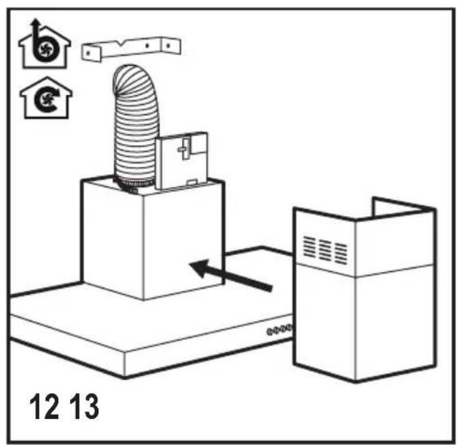
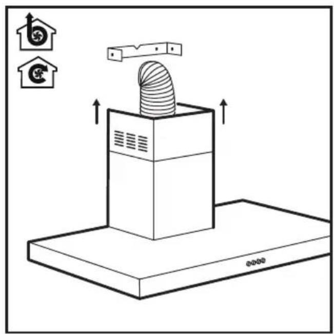
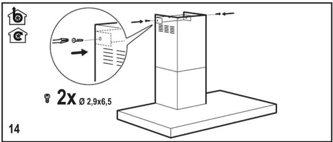

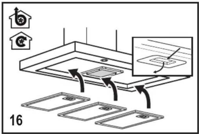
SAFETY INSTRUCTIONS
Caution! Closely follow the instructions set out in this manual. All responsibility, for any eventual inconveniences, damages or fires caused by not complying with the instructions in this manual, is declined. The extractor hood has been designed exclusively for domestic use.
Caution! Do not connect the appliance to the mains until the installation is fully complete. Before any cleaning or maintenance operation, disconnect hood from the mains by removing the plug or disconnecting the mains electrical supply.
Always wear work gloves for all installation and maintenance operations. The appliance is not intended for use by children or persons with impaired physical, sensorial or mental faculties, or if lacking in experience or knowledge, unless they are under supervision or have been trained in the use of the appliance by a person responsible for their safety. This appliance is designed to be operated by adults, children should be monitored to ensure that they do not play with the appliance. This appliance is designed to be operated by adults. Children should not be allowed to tamper with the controls or play with the appliance. Never use the hood without effectively mounted grating! The hood must NEVER be used as a support surface unless specifically indicated. The premises where the appliance is stalled must be sufficiently ventilated, when the kitchen hood is used together with other gas combustion devices or other fuels. The ducting system for this appliance must not be connected to any existing ventilation system which is being used for any other purpose such as discharging exhaust fumes from appliances burning gas or other fuels. The flaming of foods beneath the hood itself is severely prohibited. The use of exposed flames is detrimental to the filters and may cause a fire risk, and must therefore be avoided in all circumstances. Any frying must be done with care in order to make sure that the oil does not overheat and ignite.
Caution! Accessible parts of the hood may become hot when used with cooking appliance.
With regards to the technical and safety measures to be adopted for fume discharging it is important to closely follow the regulations provided by the local authorities. The hood
must be regularly cleaned on both the inside and outside (AT LEAST ONCE A MONTH). This must be completed in accordance with the maintenance instructions provided in this manual). Failure to follow the instructions provided in this user guide regarding the cleaning of the hood and filters will lead to the risk of fires. Do not use or leave the hood without the lamp correctly mounted due to the possible risk of electric shocks. We will not accept any responsibility for any faults, damage or fires caused to the appliance as a result of the non-observance of the instructions included in this manual.
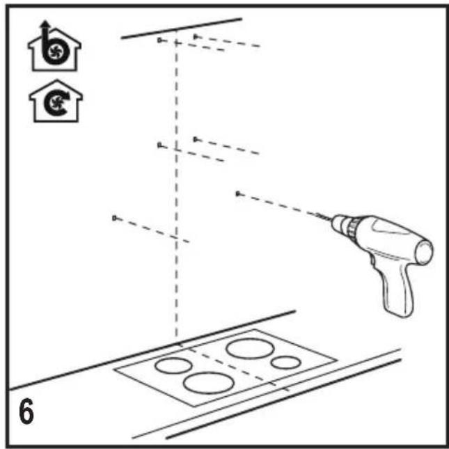
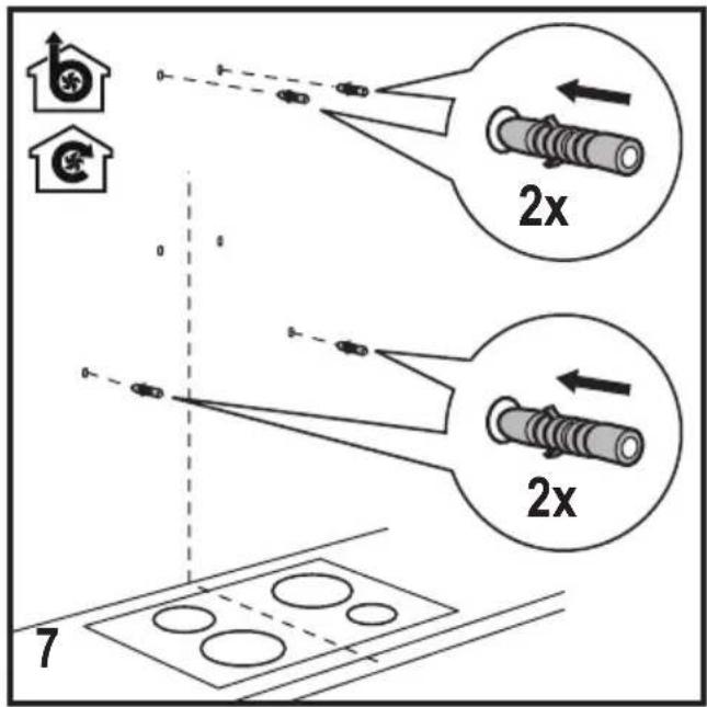
Warning! Failure to install the screws or fixing device in accordance with these instructions may result in electrical hazards.
ENVIRONMENT CONCERNS
Recycle the materials with the symbol
Put the packaging in applicable containers to recycle it. Help protect the environment and human health and to recycle waste of electrical and electronic appliances. Do not dispose
appliances marked with the symbol with the household waste. Return the product to your local recycling facility or contact your municipal office department for household waste or the shop where you purchased this product.
USE
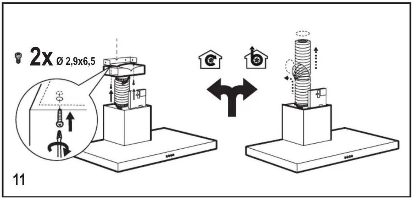
The hood is designed to be used either for
exhausting 📋 or filter version 🌐
INSTALLATION
The mains power supply must correspond to the rating indicated on the plate situated inside the hood. If provided with a plug connect the hood to a socket in compliance with current regulations and positioned in an accessible area, after installation. If it not fitted with a plug (direct mains connection) or if the plug is not located in an accessible area, after installation, apply a double pole switch in accordance with standards which assures the complete disconnection of the mains under conditions relating to over-current category III in accordance with installation instructions.
Warning! Before re-connecting the hood circuit to the mains supply and checking the efficient function, always check that the mains cable is correctly assembled.
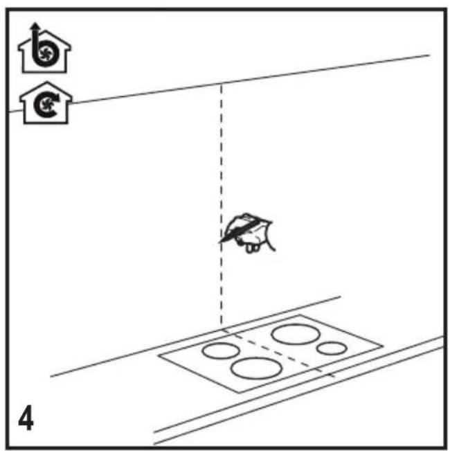
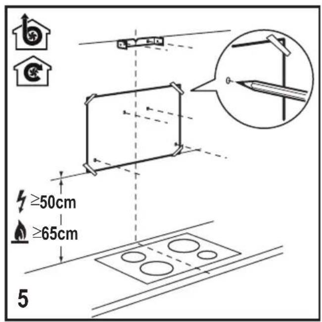
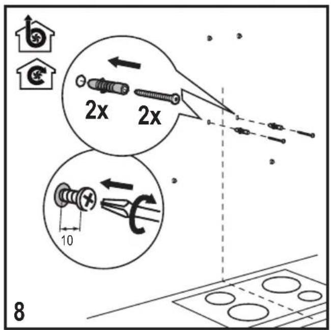
The minimum distance between the supporting surface for the cooking equipment on the hob and the lowest part of the range hood must be not less than 50cm from electric cookers and 65cm from gas or mixed cookers. If the instructions for installation for the gas hob specify a greater distance, this must be adhered to.
MAINTENANCE

ATTENTION! Before performing any maintenance operation, isolate the hood from the electrical supply by switching off at the connector and removing the connector fuse. Or if the appliance has been connected through a plug and socket, then the plug must be removed from the socket.
The cooker hood should be cleaned regularly (at least with the same frequency with which you carry out maintenance of the fat filters) internally and externally. Clean using the cloth dampened with neutral liquid detergent. Do not use abrasive products. DO NOT USE ALCOHOL!

Warning! Failure to carry out the basic cleaning recommendations of the cooker hood and replacement of the filters may cause fire risks. Therefore, we recommend observing these instructions. The manufacturer declines all responsibility for any damage to the motor or any fire damage linked to inappropriate maintenance or failure to observe the above safety recommendations.
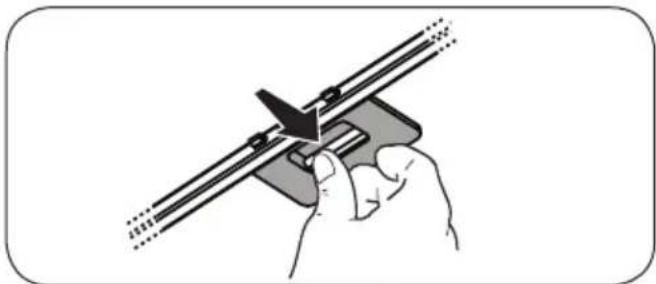
Grease filter - The grease filter must be cleaned once a month using non aggressive detergents, either by hand or in the dishwasher, which must be set to a low temperature and a short cycle. When washed in a dishwasher, the grease filter may discolour slightly, but this does not affect its filtering capacity.
natural_image
Illustration of a hand using a tool to adjust or install a mechanical component (no text or symbols visible)Charcoal filter - Type 20 LONG LIFE - Washable activated charcoal filter
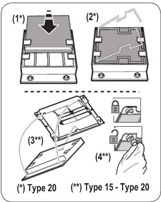
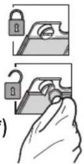
The charcoal filter can be washed once every two months using hot water and a suitable detergent, or in a dishwasher at 65irc C (if the dishwasher is used, select the full cycle function and leave dishes out).
Eliminate excess water without damaging the filter, then remove the mattress located inside the plastic frame and put it in the oven for 10 minutes at 100irc C to dry completely. Replace the mattress every 3 years and when the cloth is damaged.
Type 15 - NON-washable activated charcoal filter
The saturation of the charcoal filter occurs after more or less prolonged use, depending on the type of cooking and the regularity of cleaning of the grease filter. In any case it is necessary to replace the cartridge at least every four mounths. The charcoal filter may NOT be washed or regenerated.
CONTROLS
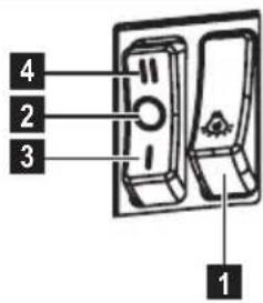
The hood is fitted with a control panel with aspiration speed selection control and a light switch to control cooking area lights.
-
ON/OFF lighting
-
OFF motors
-
-
-
-
- Minimum suction power (3.), medium (4.), maximum (5.)
-
-
-
Use the high suction speed in cases of concentrated kitchen vapours. It is recommended that the cooker hood suction is switched on for 5 minutes prior to cooking and to leave in operation during cooking and for another 15
minutes approximately after terminating cooking.
LIGHTING
Disconnect the hood from the electricity.
Warning! Prior to touching the light bulbs ensure they are cooled down.
Replace the damaged lamp.
Use ∅35mm E14 28W halogen candle lamps only.
natural_image
Illustration of a hand using a tool to adjust or install a mechanical component (no text or symbols visible)natural_image
Illustration of a hand using a tool to adjust or install a mechanical component (no text or symbols visible)natural_image
Diagram of a mechanical component with a downward arrow and mounting holes (no text or symbols)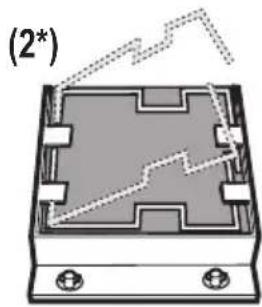
natural_image
Diagram of a device casing with mounting holes and internal circuit lines (no text or symbols)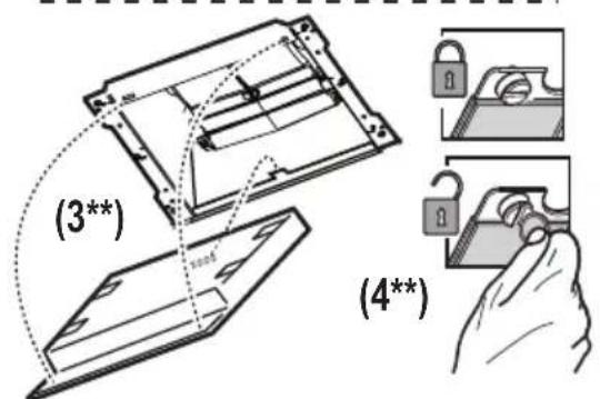
(*) Type 20
(**) Type 15 - Type 20
COMMANDES
natural_image
Illustration of a hand using a tool to adjust or install a mechanical component (no text or symbols visible)Type 20 LONG LIFE - Wasbaar koolstofffilter
natural_image
Illustration of a hand using a tool to adjust or install a mechanical component (no text or symbols visible)natural_image
Diagram of a mechanical component with a downward arrow and mounting holes (no text or symbols)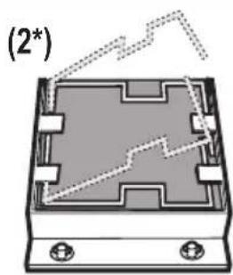
natural_image
Diagram of a device casing with mounting holes and internal circuit lines (no text or symbols)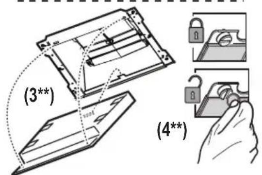
(*) Type 20
(**) Type 15 - Type 20
MANDOS
natural_image
Illustration of a hand using a tool to adjust or install a mechanical component (no text or symbols visible)Type 20 LONG LIFE - Filtro de carvão acrivolavável
natural_image
Diagram of a mechanical component with a downward arrow and labeled point (1*), no readable text or symbols present.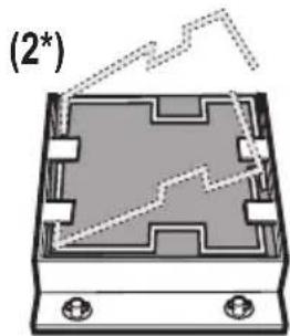
natural_image
Diagram of a rectangular electronic component with internal circuitry and mounting holes, no text or symbols present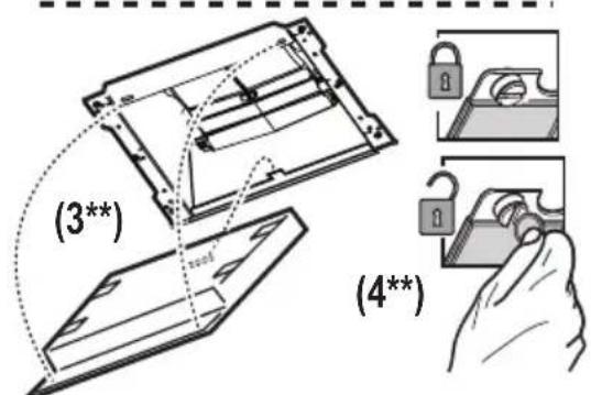
(*) Type 20
(**) Type 15 - Type 20
COMANDOS
natural_image
Illustration of a hand using a tool to cut or adjust a mechanical component (no text or symbols visible)natural_image
Illustration of a hand using a tool to adjust or install a mechanical component (no text or symbols visible)Kolfilter - Type 20 LONG LIFE - Aktivt kolfilter som kan rengöras
natural_image
Illustration of a hand using a tool to adjust or install a mechanical component (no text or symbols visible)Type 20 LONG LIFE - Vaskbart aktivt kullfilter
natural_image
Diagram of a rectangular electronic component with mounting holes and internal circuit lines (no text or symbols)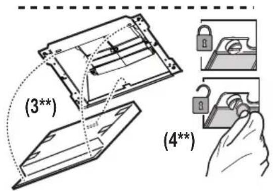
(*) Type 20
(**) Type 15 - Type 20
KONTROLLER
natural_image
Illustration of a hand using a tool to cut or adjust a mechanical component (no text or symbols visible)natural_image
Diagram of a mechanical component with a downward arrow and mounting holes (no text or symbols)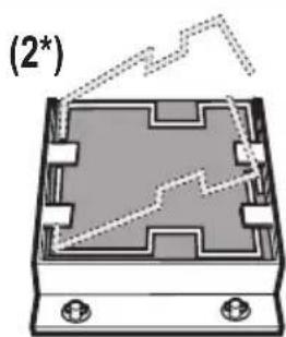
natural_image
Diagram of a device casing with internal components and mounting holes, labeled (2*), showing no readable text or symbols.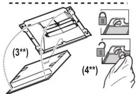
(*) Type 20
(**) Type 15 - Type 20
OHJAIMET
natural_image
Illustration of a hand using a tool to adjust or install a mechanical component (no text or symbols visible)natural_image
Illustration of a hand holding a tool with a bracket and arrow, no text or symbols presentnatural_image
Illustration of a hand using a tool to adjust or install a mechanical component (no text or symbols visible)Type 20 LONG LIFE - Pestav aktiivsöefilter
natural_image
Diagram of a device casing with internal components and a dashed line indicating a trajectory or path (no text or symbols)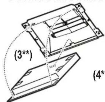
(*) Type 20
(**) Type 15 - Type 20
JUHIKUD
natural_image
Illustration of a hand using a tool to adjust or install a mechanical component (no text or symbols visible)natural_image
Illustration of a hand using a tool to adjust or install a mechanical component (no text or symbols visible)Type 20 LONG LIFE - Plaunamas aktyviosios anglies filtras
natural_image
Illustration of a hand using a tool to adjust or install a mechanical component (no text or symbols visible)natural_image
Illustration of a hand using a tool to cut or adjust a mechanical component (no text or symbols visible)natural_image
Diagram of a mechanical component with a downward arrow and mounting holes (no text or symbols)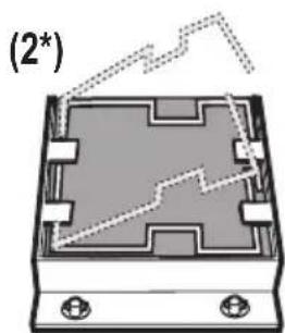
natural_image
Diagram of a device casing with internal components and mounting holes, labeled (2*), showing no readable text or symbols.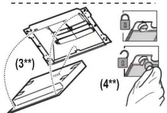
(*) Type 20
(**) Type 15 - Type 20
KEZELŐSZERVEK
natural_image
Illustration of a hand using a tool to cut or adjust a mechanical component (no text or symbols visible)natural_image
Illustration of a hand using a tool to adjust or install a mechanical component (no text or symbols visible)Type 20 LONG LIFE - Aktívno uhlíkový filter umývatel'ný
natural_image
Diagram of a mechanical component with a downward arrow and mounting holes (no text or symbols)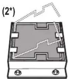
natural_image
Diagram of a rectangular electronic component with internal circuitry and mounting holes, labeled (2*), showing no readable text or symbols.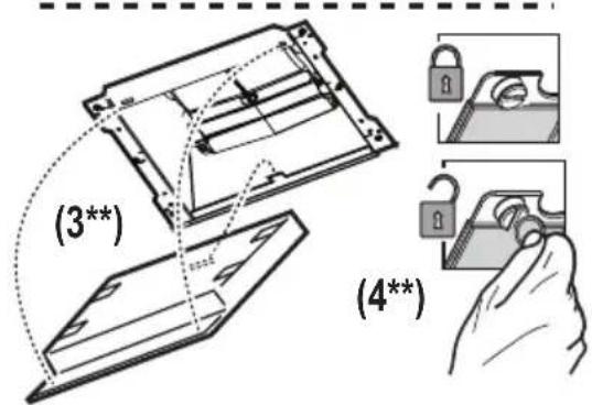
(*) Type 20
(**) Type 15 - Type 20
OVLÁDAČE
natural_image
Illustration of a hand using a tool to adjust or install a mechanical component (no text or symbols visible)Type 20 LONG LIFE - Filtru cu carbon activ lavabil
natural_image
Illustration of a hand using a tool to adjust or install a mechanical component (no text or symbols visible)natural_image
Illustration of a hand using a tool to adjust or install a mechanical component (no text or symbols visible)natural_image
Illustration of a hand using a tool to cut or adjust a mechanical component (no text or symbols visible)Type 20 LONG LIFE - Pralni filter z aktivnim ogljem
natural_image
Diagram of a mechanical component with a downward arrow and mounting holes, labeled (1*) (no text or symbols on the diagram itself)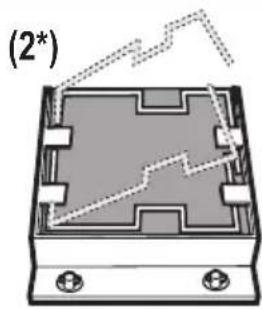
natural_image
Diagram of a device casing with internal components and a dashed line indicating a trajectory (no text or symbols)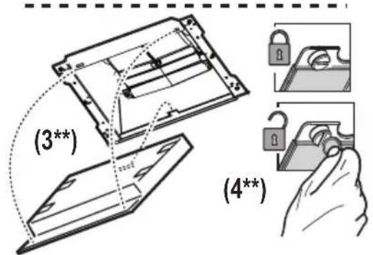
(*) Type 20 (**) Type 15 - Type 20
UPRAVLJALNI GUMBI
natural_image
Illustration of a hand using a tool to adjust or install a mechanical component (no text or symbols visible)natural_image
Diagram of a mechanical component with a downward arrow and mounting holes (no text or symbols)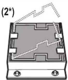
natural_image
Diagram of a device casing with internal components and a dashed line indicating a trend or path (no text or symbols)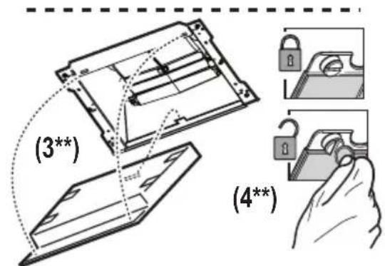
(*) Type 20 (**) Type 15 - Type 20
ΧΕΙΡΙΣΤΗΡΙΑ
natural_image
Illustration of a hand using a tool to adjust or install a mechanical component (no text or symbols visible)Type 20 LONG LIFE - Yıkanabilir aktif karbon filtre
natural_image
Diagram of a mechanical component with a downward arrow and mounting holes (no text or symbols)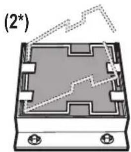
natural_image
Diagram of a rectangular electronic component with internal circuitry and mounting holes, no text or symbols present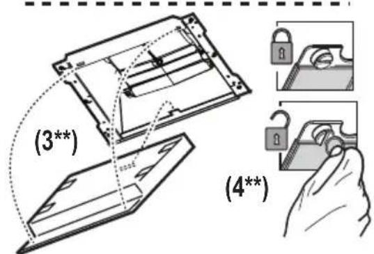
(*) Type 20
(**) Type 15 - Type 20
KONTROLLER
natural_image
Illustration of a hand using a tool to cut or adjust a mechanical component (no text or symbols visible)natural_image
Diagram of a device casing with mounting holes and internal circuit lines (no text or symbols)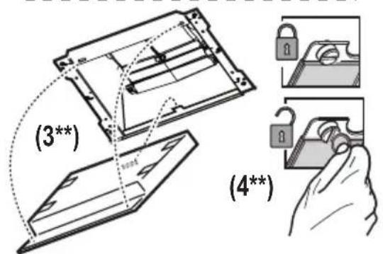
(*) Type 20 (**) Type 15 - Type 20
УПРАВЛЕНИЯ
natural_image
Illustration of a hand using a tool to adjust or install a mechanical component (no text or symbols visible)natural_image
Diagram of a mechanical component with a downward arrow and base plate (no text or symbols)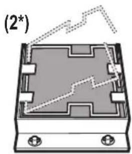
natural_image
Diagram of a device casing with internal components and a dashed line indicating a trajectory (no text or symbols)
(*) Type 20
(**) Type 15 - Type 20
БАСКАРУ ЭЛЕМЕНТТЕРІ
natural_image
Illustration of a hand using a tool to adjust or install a mechanical component (no text or symbols visible)natural_image
Illustration of a hand using a tool to adjust or install a mechanical component (no text or symbols visible)natural_image
Illustration of a hand using a tool to adjust or install a mechanical component (no text or symbols visible)natural_image
Diagram of a mechanical component with a downward arrow and mounting holes (no text or symbols)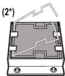
natural_image
Diagram of a rectangular electronic component with mounting holes and internal circuit lines (no text or symbols)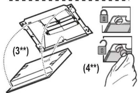
(*) Type 20
(**) Type 15 - Type 20
КОМАНДЕ
natural_image
Mechanical component diagram showing a downward arrow and mounting base (no text or symbols)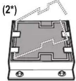
natural_image
Diagram of a rectangular electronic component with internal circuitry and mounting holes, no text or symbols present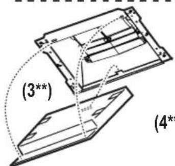
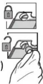
(*) Type 20
(**) Type 15 - Type 20
natural_image
Illustration of a hand using a tool to adjust or install a mechanical component (no text or symbols visible)اعتبارات بینية

لسلامة.
natural_image
Four icon buttons representing different product categories: washing machine, washing machine with gear, shopping cart, and shopping cart (no text or symbols)
- SAFETY INSTRUCTIONS
- ENVIRONMENT CONCERNS
- USE
- INSTALLATION
- MAINTENANCE
- Charcoal filter - Type 20 LONG LIFE - Washable activated charcoal filter
- Type 15 - NON-washable activated charcoal filter
- CONTROLS
- LIGHTING
- COMMANDES
- Type 20 LONG LIFE - Wasbaar koolstofffilter
- MANDOS
- Type 20 LONG LIFE - Filtro de carvão acrivolavável
- COMANDOS
- Kolfilter - Type 20 LONG LIFE - Aktivt kolfilter som kan rengöras
- Type 20 LONG LIFE - Vaskbart aktivt kullfilter
- KONTROLLER
- OHJAIMET
- Type 20 LONG LIFE - Pestav aktiivsöefilter
- JUHIKUD
- Type 20 LONG LIFE - Plaunamas aktyviosios anglies filtras
- KEZELŐSZERVEK
- Type 20 LONG LIFE - Aktívno uhlíkový filter umývatel'ný
- OVLÁDAČE
- Type 20 LONG LIFE - Filtru cu carbon activ lavabil
- Type 20 LONG LIFE - Pralni filter z aktivnim ogljem
- UPRAVLJALNI GUMBI
- ΧΕΙΡΙΣΤΗΡΙΑ
- Type 20 LONG LIFE - Yıkanabilir aktif karbon filtre
- УПРАВЛЕНИЯ
- БАСКАРУ ЭЛЕМЕНТТЕРІ
- КОМАНДЕ
- اعتبارات بینية
Brand : ZANKER
Model : KHC92460XK
Category : Range hood