
AA 04 - TV Antenna ZEHNDER - Free user manual and instructions
Find the device manual for free AA 04 ZEHNDER in PDF.
| Product type | Indoor digital TV antenna |
| Brand | Zehnder |
| Model | AA 04 |
| Dimensions (L x W x H) | 139 x 209 x 23 mm |
| Weight | 210 g |
| Frequency range | VHF 47-230 MHz (channels 02-12), UHF 470-860 MHz (channels 21-69) |
| Gain | 21 ±3 dB |
| Main power supply | Power adapter 230 V - 9 VDC/100 mA |
| Alternative power supply | Via DTT receiver 5 V/40 mA through coaxial cable (core +, braid -) |
| Amplifier | Built-in active |
| Interference filter | Integrated filter against GSM signals |
| Installation | On stand (free-standing) or wall mounting (kit included) |
| Orientation | Horizontal or vertical |
| Included items | Antenna, support stand, wall mounting kit, 2 m coaxial extension cable, power adapter |
| Care and cleaning | Disconnect before cleaning, use a soft slightly damp cloth |
| Safety | Do not expose to direct sunlight or heat sources, avoid humidity, use only the supplied power adapter |
| Compatibility | DTT, terrestrial digital reception and radio (VHF/UHF) |
| Disposal | Recycle at an official collection point for WEEE (in accordance with directive 2002/96/EC) |
Frequently Asked Questions - AA 04 ZEHNDER
User questions about AA 04 ZEHNDER
0 question about this device. Answer the ones you know or ask your own.
Ask a new question about this device
Download the instructions for your TV Antenna in PDF format for free! Find your manual AA 04 - ZEHNDER and take your electronic device back in hand. On this page are published all the documents necessary for the use of your device. AA 04 by ZEHNDER.
USER MANUAL AA 04 ZEHNDER
Digital DVB-T Zimmerantenne
natural_image
Front view of a white rectangular electronic device with a blank screen (no visible text or symbols)Merkmale
natural_image
Exterior view of a plain rectangular frame with rounded edges and a flat base (no text or symbols visible)Anschlüsse:
Technische Daten:
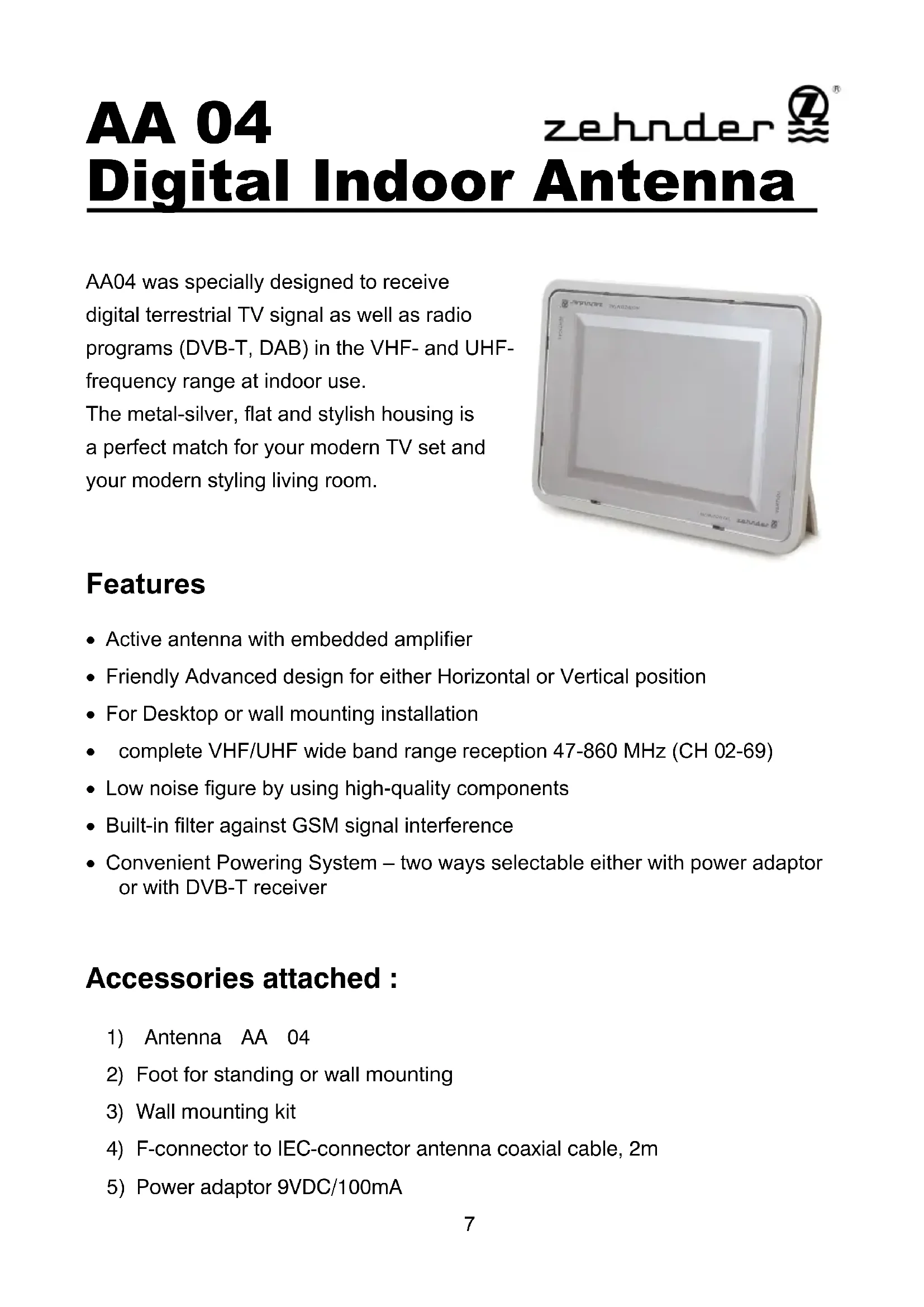
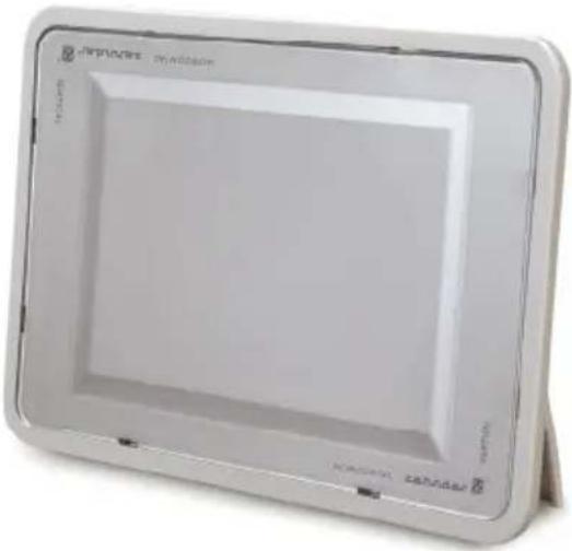
AA04 was specially designed to receive digital terrestrial TV signal as well as radio programs (DVB-T, DAB) in the VHF- and UHF-frequency range at indoor use.
The metal-silver, flat and stylish housing is a perfect match for your modern TV set and your modern styling living room.
natural_image
Exterior view of a white rectangular electronic device with no visible text or symbols on the bodyFeatures
• Active antenna with embedded amplifier
- Friendly Advanced design for either Horizontal or Vertical position
- For Desktop or wall mounting installation
- complete VHF/UHF wide band range reception 47-860 MHz (CH 02-69)
- Low noise figure by using high-quality components
• Built-in filter against GSM signal interference
- Convenient Powering System – two ways selectable either with power adaptor or with DVB-T receiver
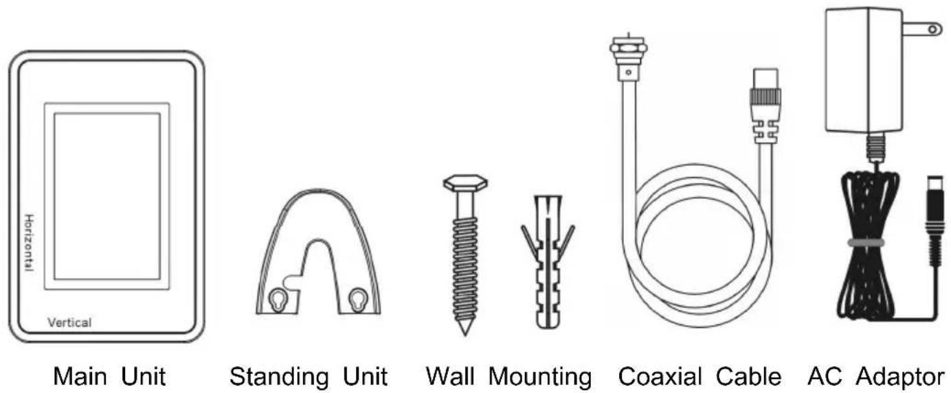
Accessories attached :
1) Antenna AA 04
2) Foot for standing or wall mounting
3) Wall mounting kit
4) F-connector to IEC-connector antenna coaxial cable, 2m
5) Power adaptor 9VDC/100mA
Location and Installation Notes:
- Operate the antenna only at dry indoor places.
- Rooms with windows are the most suitable locations to get best reception quality with sufficiently high signal level.
- Do not subject it to direct sunlight for longer periods, because material can change for the worse.
- Do not place the antenna close to heaters or naked lights (e.g. candles). There might be a danger of fire!
- Place the antenna on a safe and firm ground.
- Protect the device from moisture, drips and splashes.
Cleaning
Before cleaning, unplug the antenna from power and antenna cable. Use only a soft and slightly moistened cloth to clean the casing.
Operation Notes:
- In areas with low or too high reception-field strength, interference-free reception is not always guaranteed. If the signal level is too low, a directional antenna should be placed outside the building.
- In the immediate vicinity of the transmitter, reception may be impaired by a too high reception level. In this case, you should avoid setting up the antenna near a window.
-
Indoor radio reception can also be impaired by other factors:
-
rooms in reinforced concrete buildings
- rooms with vapour-plated windows
- in positions directly beside transmitting electronic devices (e.g. mobile phones)
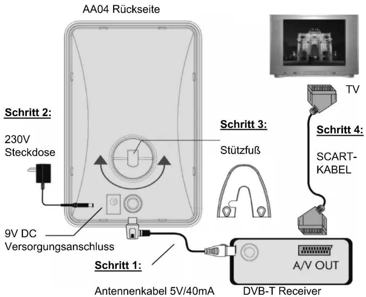
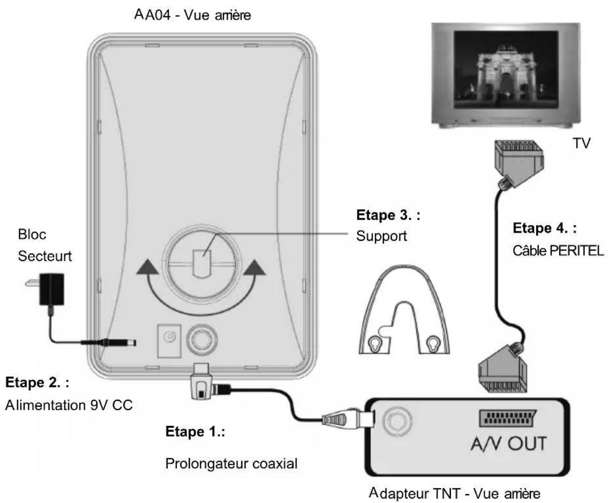
Installation (Please refer to illustration):
Step 1. Take the IEC cable attached, and then connect one end to the IEC port, and the other end to your DVB-T receiver shown in illustration Attention! Don't connect to a Satellite-Receiver!
Step 2. Take the power adaptor attached and Insert the end of DC connector into DC jack on the back of AA04, and then plug in the A/C end.
***** If your DVB-T receiver (e.g. Zehnder TX 60) supplies with 5 VDC from IEC connector, then it is not necessary to use the power adaptor.
Step 3. Take the standing unit attached, and then plug into the hole shown in illustration to keep it standing. Before, check the position of rotating hole for either vertical or horizontal direction.
Step 4. Connect your receiver and your TV by Scart Cable (see receiver manual) and switch them on.
***** If your DVB-T receiver supplies with 5 VDC, ensure in the set-up menu of the receiver, that the power supply to the antenna via the coax cable is switched on.
Tips for correct Antenna Adjustment
To verify the quality of reception, you can use either the TV picture or the option of displaying the reception level and signal quality in the set-up menu of your receiver.
If reception is subject to interference, turn the antenna slightly, or alter the direction of polarisation by titling it sideways (horizontal – vertical), and check the quality of reception.
If it is impossible to get optimum reception, set the antenna up in a different place (we recommend a position close to a window), and repeat the steps described above.
Even for wall mounting installation, before you should check antenna position at the wall and in the room for best possible reception quality.

natural_image
Exterior view of a rectangular electronic device with a flat top and side supports (no visible text or symbols)Connecting Illustration

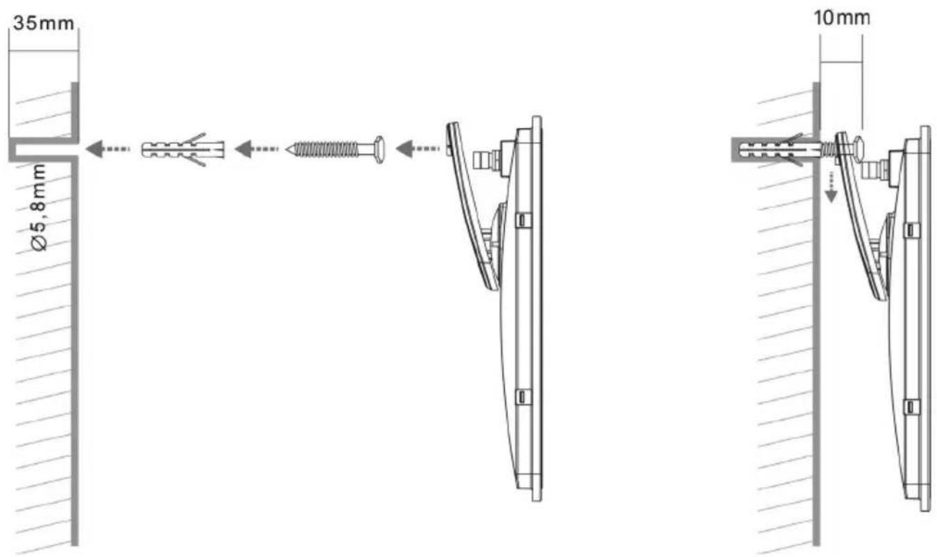
Wall mounting installation (see sketch)
- After you found the best location to place the antenna at the wall, mark with a pencil the 2 positions for the wholes to fix the standing unit.
- Drill with a 5,8mm-drill the two wholes into the depth of about 35mm. (If you install to a wooden wall you do not need to drill and use the plastic poles)
- Hammer the two plastic poles with a hammer into the wholes.
- Screw the screws with a screwdriver into the plastic pole as far as you still easily can hook the standing unit of the antenna. Leave the screws about 10mm out of the wall.
- Connect all cables and hook the antenna onto the screws.
Specifications:
| Frequency Range | VHF 47~230MHz, CH 02~12UHF 470~860MHz, CH 21~69, |
| Amplifier Gain 21 ±3 dB | |
| Two Powering selection | with adaptor 9V/100mAwith DVB-T receiver 5V/40mA(center "+" , outer"-" ) |
| Power adaptor AC ~230V/50Hz; | DC 9V/100mA |
| Weight | ~210g |
| Size: L x W x H (mm) 139 x 209 x 23 | |
Disposal
Electronic equipment is not household waste. In accordance with directive 2002/96/EC OF THE EUROPEAN PARLIAMENT AND THE COUNCIL of 27th January 2003 on used electrical and electronic equipment, it must be disposed of properly.

„At the end of its service life, take this unit for disposal at the designated public collection points."
natural_image
Exterior view of a white rectangular electronic device with no visible text or symbols on the body (text is partially legible)Dispositifs
natural_image
Exterior view of a rectangular electronic device with a flat top and side connectors (no visible text or symbols)Connecting Illustration
Spécifications :

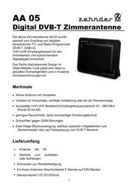
- Digital DVB-T Zimmerantenne
- Merkmale
- Anschlüsse:
- Features
- Accessories attached :
- Location and Installation Notes:
- Cleaning
- Operation Notes:
- Installation (Please refer to illustration):
- Tips for correct Antenna Adjustment
- Connecting Illustration
- Wall mounting installation (see sketch)
- Disposal
- Dispositifs
Brand : ZEHNDER
Model : AA 04
Category : TV Antenna