
07E00119B - Range hood BEST - Free user manual and instructions
Find the device manual for free 07E00119B BEST in PDF.
| Brand | Best |
| Model | 07E00119B |
| Product type | Kitchen hood |
| Installation | Extracting or recirculating |
| Grease filters | Metal or synthetic (cleaning every 30 hours of operation) |
| Charcoal filters | Optional for recirculating version (replace every 120 hours or every 6 months) |
| Lighting | Halogen or LED depending on model |
| Controls | Touch or switches (several types depending on model) with timer and automatic sensor |
| Motor speeds | Up to 4 speeds |
| Filter alarm | Yes (indicator light or central segment lit or flashing) |
| Stop timer | 5 minutes |
| Exhaust duct diameter | 123 mm or 150 mm depending on model |
| Power supply | 220-240 V ~50/60 Hz |
| Supplied accessories | Fixing screws, metal grille, grease filters (charcoal filters not supplied) |
| Repairability | Spare parts available through technical service |
| Safety | Installation by specialist recommended; damaged cable must be replaced by a professional |
Frequently Asked Questions - 07E00119B BEST
User questions about 07E00119B BEST
0 question about this device. Answer the ones you know or ask your own.
Ask a new question about this device
Download the instructions for your Range hood in PDF format for free! Find your manual 07E00119B - BEST and take your electronic device back in hand. On this page are published all the documents necessary for the use of your device. 07E00119B by BEST.
USER MANUAL 07E00119B BEST
INSTRUCTIONS FOR INSTALLATION AND USE
If the supply cord is damaged, it must be replaced by the manufacturer, its service agent or similarly qualified persons in order to avoid a hazard.
DESCRIPTION
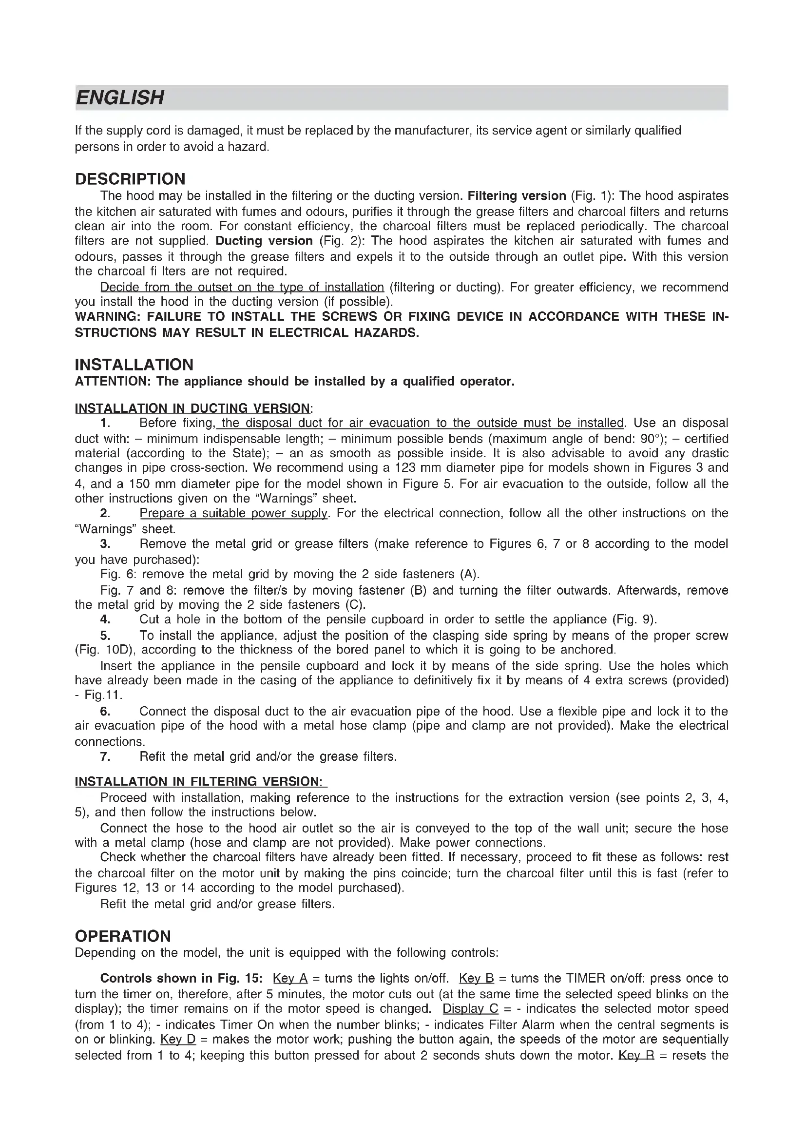
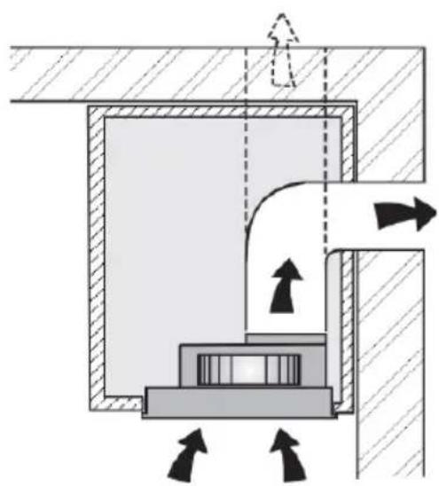
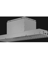
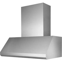
The hood may be installed in the filtering or the ducting version. Filtering version (Fig. 1): The hood aspirates the kitchen air saturated with fumes and odours, purifies it through the grease filters and charcoal filters and returns clean air into the room. For constant efficiency, the charcoal filters must be replaced periodically. The charcoal filters are not supplied. Ducting version (Fig. 2): The hood aspirates the kitchen air saturated with fumes and odours, passes it through the grease filters and expels it to the outside through an outlet pipe. With this version the charcoal filters are not required.
Decide from the outset on the type of installation (filtering or ducting). For greater efficiency, we recommend you install the hood in the ducting version (if possible).
WARNING: FAILURE TO INSTALL THE SCREWS OR FIXING DEVICE IN ACCORDANCE WITH THESE INSTRUCTIONS MAY RESULT IN ELECTRICAL HAZARDS.
INSTALLATION
ATTENTION: The appliance should be installed by a qualified operator.
INSTALLATION IN DUCTING VERSION:
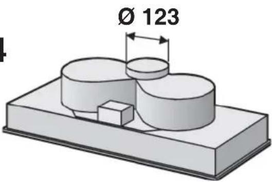
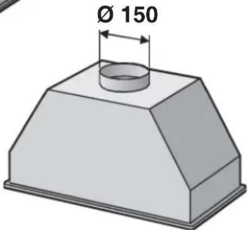
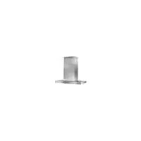
- Before fixing, the disposal duct for air evacuation to the outside must be installed. Use an disposal duct with: – minimum indispensable length; – minimum possible bends (maximum angle of bend: 90^ ); – certified material (according to the State); – an as smooth as possible inside. It is also advisable to avoid any drastic changes in pipe cross-section. We recommend using a 123 mm diameter pipe for models shown in Figures 3 and 4, and a 150 mm diameter pipe for the model shown in Figure 5. For air evacuation to the outside, follow all the other instructions given on the “Warnings” sheet.
- Prepare a suitable power supply. For the electrical connection, follow all the other instructions on the "Warnings" sheet.
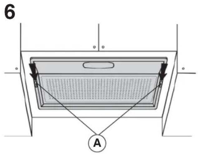
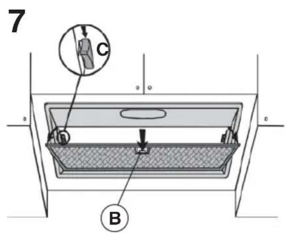
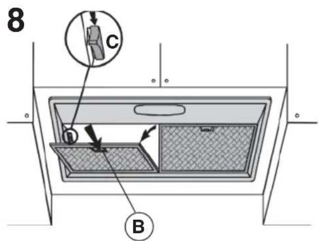
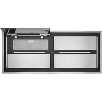
- Remove the metal grid or grease filters (make reference to Figures 6, 7 or 8 according to the model you have purchased):
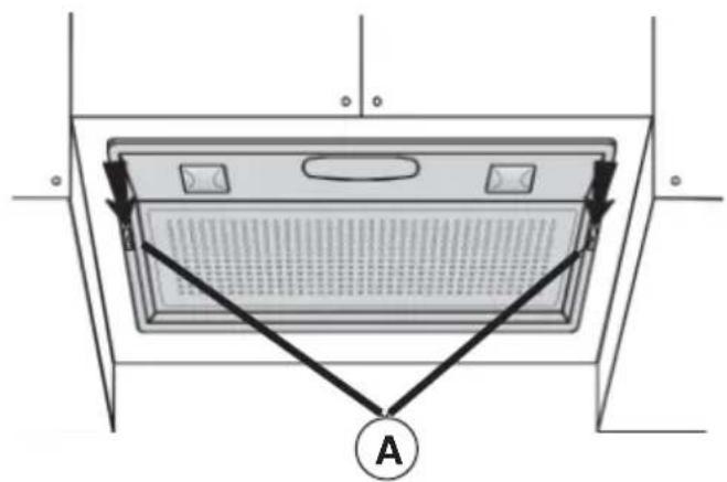
Fig. 6: remove the metal grid by moving the 2 side fasteners (A).
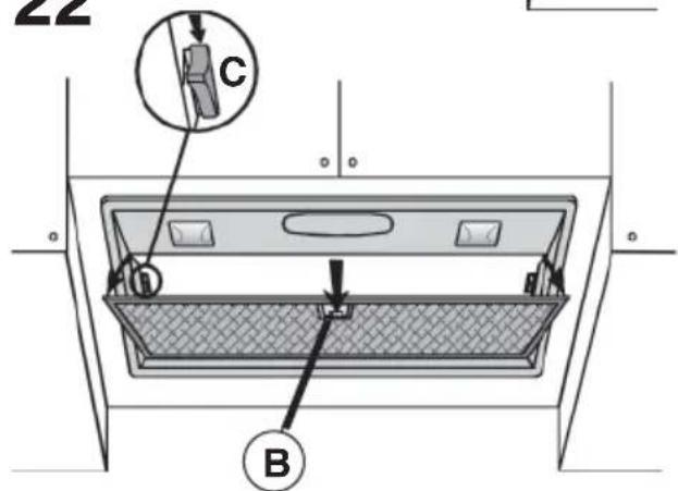
Fig. 7 and 8: remove the filter/s by moving fastener (B) and turning the filter outwards. Afterwards, remove the metal grid by moving the 2 side fasteners (C).
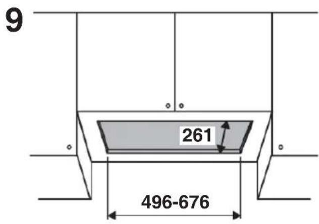
4. Cut a hole in the bottom of the pensile cupboard in order to settle the appliance (Fig. 9).
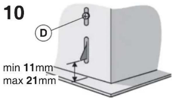
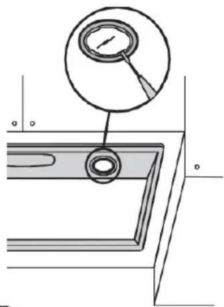
5. To install the appliance, adjust the position of the clasping side spring by means of the proper screw (Fig. 10D), according to the thickness of the bored panel to which it is going to be anchored.
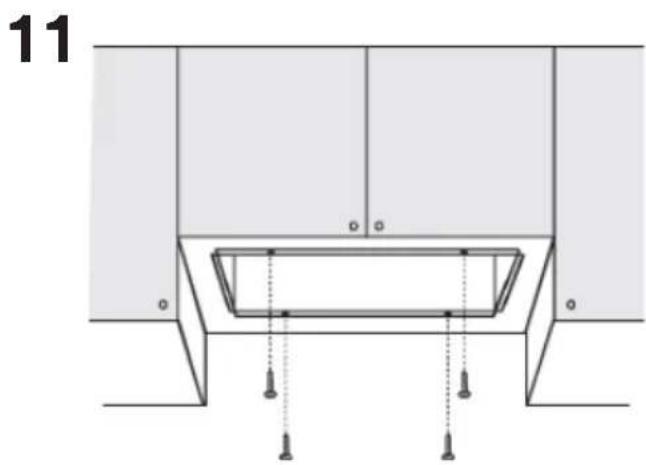
Insert the appliance in the penile cupboard and lock it by means of the side spring. Use the holes which have already been made in the casing of the appliance to definitively fix it by means of 4 extra screws (provided) - Fig.11.
6. Connect the disposal duct to the air evacuation pipe of the hood. Use a flexible pipe and lock it to the air evacuation pipe of the hood with a metal hose clamp (pipe and clamp are not provided). Make the electrical connections.
7. Refit the metal grid and/or the grease filters.
INSTALLATION IN FILTERING VERSION:
Proceed with installation, making reference to the instructions for the extraction version (see points 2, 3, 4, 5), and then follow the instructions below.
Connect the hose to the hood air outlet so the air is conveyed to the top of the wall unit; secure the hose with a metal clamp (hose and clamp are not provided). Make power connections.
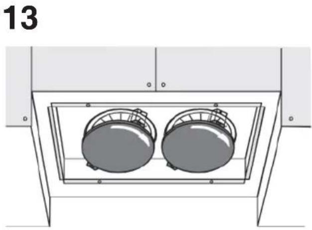
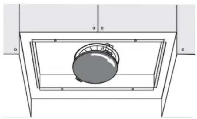
Check whether the charcoal filters have already been fitted. If necessary, proceed to fit these as follows: rest the charcoal filter on the motor unit by making the pins coincide; turn the charcoal filter until this is fast (refer to Figures 12, 13 or 14 according to the model purchased).
Refit the metal grid and/or grease filters.
OPERATION
Depending on the model, the unit is equipped with the following controls:
Controls shown in Fig. 15: Key A = turns the lights on/off. Key B = turns the TIMER on/off: press once to turn the timer on, therefore, after 5 minutes, the motor cuts out (at the same time the selected speed blinks on the display); the timer remains on if the motor speed is changed. Display C = - indicates the selected motor speed (from 1 to 4); - indicates Timer On when the number blinks; - indicates Filter Alarm when the central segments is on or blinking. Key D = makes the motor work; pushing the button again, the speeds of the motor are sequentially selected from 1 to 4; keeping this button pressed for about 2 seconds shuts down the motor. Key R = resets the
grease filters or charcoal filters; when the filter alarm appears (i.e. when the central segment on the display goes on), the grease filters must be cleaned (30 hours of operation); when the central segment starts blinking, the grease filters must be cleaned and the charcoal filters replaced (120 hours of operation). Obviously, if the hood is not a filtering model and does not have a charcoal filter, clean the grease filters both when the central segment goes on and when it starts blinking. The filter alarm can be seen when the motor is off and for about 30 seconds. To reset the hour counter, keep the button pressed for 2 seconds while the alarm can be seen.
Controls shown in Fig. 16:
AUTOMATIC OPERATION WITH SENSOR:
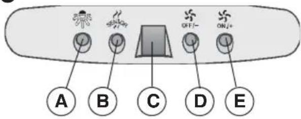
Key A : switches the lights on/off. Key B : enables/disables "Automatic" function. When this function is selected, an "A" appears on the display C, and the speed of the motor increases or decreases depending on the smoke, odours and gas present in the kitchen. Display C : - indicates the automatic operation of the sensor (the letter "A" appears);- indicates the motor speed selected automatically by the sensor; indicates the filter alarm whenever the central segment is illuminated or flashing. Key D : decreases motor speed / Reset; decreases motor speed to zero (stopping); in any case however, after approximately 1 minute, the hood resumes automatic operation at the speed set by the sensor. Whenever the key is pressed during the display of filter alarms, a RESET occurs, and the counting of the hours resumes again. Key E : increases motor speed; in any case however, after approximately 1 minute, the hood resumes automatic operation at the speed set by the sensor.
Modification of sensor sensitivity: sensor sensitivity can be modified by operating as follows:
- stop the hood by pressing key B. – Simultaneously press keys D and E (the sensor's sensitivity index will appear on the display) - Pressing keys D or E, the sensor's sensitivity will either increase or decrease (1 : minimum sensitivity / 9: maximum sensitivity). – whenever the power supply is interrupted, the sensor will resume operation with a sensitivity index of 5.
Warning: in order to avoid damaging the sensor, never use silicone products near the hood!
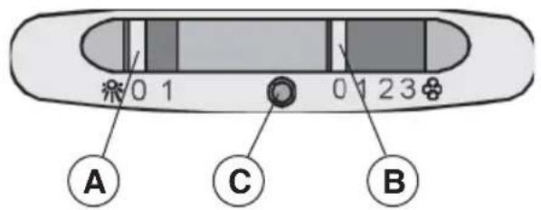
Controls shown in Fig. 17: Switch A: LIGHT; position 0: light off; position 1: light on. Switch B: MOTOR SPEED: makes it possible to select the motor operating speed; position 0: motor off. C: Motor on light.
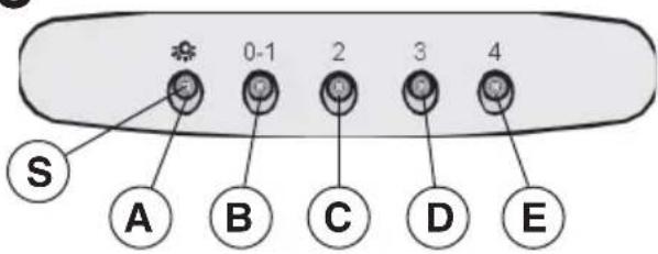
Controls shown in Fig. 18: Key A: turns the lights on/off; every 30 hours of operation the corresponding pilot lamp (S) comes on to indicate that the grease filters must be cleaned; every 120 hours of operation the corresponding pilot lamp (S) flashes to indicate that the grease filters must be cleaned and the charcoal filter replaced. To restart the hour counter (RESET), hold the button A pressed down for about 1" (while the pilot lamp S is on). Key B: drives the motor in first speed (the corresponding pilot lamp comes on); when holding it down for about 1", the motor cuts out; when pressing the button a second time (while the pilot lamp is on), the TIMER is activated and thus the motor stops after 5' (the pilot lamp flashes). Key C: drives the motor in second speed (the corresponding pilot lamp comes on); when pressing the button a second time (while the pilot lamp is on), the TIMER is activated and thus the motor stops after 5' (the pilot lamp flashes). Key D: drives the motor in third speed (the corresponding pilot lamp comes on); when pressing the button a second time (while the pilot lamp is on), the TIMER is activated and thus the motor stops after 5' (the pilot lamp flashes). Key E: drives the motor in fourth speed (the corresponding pilot lamp comes on); when pressing the button a second time (while the pilot lamp is on), the TIMER is activated and thus the motor stops after 5' (the pilot lamp flashes).
Pay special attention to the grease filters: if the model purchased has the controls shown in Figure 15/16: the grease filters must be cleaned approximately once every 30 hours of operation (when the central segment on the display goes on or starts blinking). Once the cleaned filters are reinstalled, keep button R (Reset) pressed for two seconds to reset the counter. If the model purchased has the controls shown in Figure 17: the grease filter must be cleaned periodically: exactly how often depends on use (at least once every other month). Wash out the filter using a neutral soap. If the model purchased has the controls shown in Figure 18: the grease filters must be cleaned approximately once every 30 hours of operation (when the light button lamp comes on) - Fig.18S). Wash out the filter using a neutral soap. Once the cleaned filters are reinstalled, to reset the counter hold the light button pressed down for about 1" (Fig.18A) while the corresponding pilot lamp (S) is on. IMPORTANT: The metal grease filters must be periodically cleaned following the above instructions, while the synthetic grease filters (white colour) must be replaced, according to the same cleaning frequency as the metal filters.
Removing the grease fi Iters:
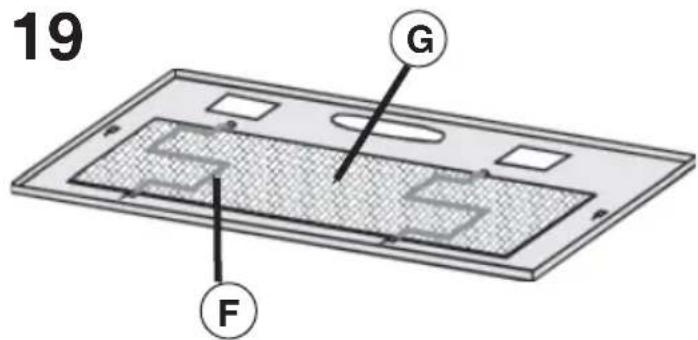
- For the model shown in Fig. 6: remove the metal grid by moving the 2 side fasteners (A). Remove the filter retainers (Fig. 19F) and then the metal (or synthetic) grease filter (Fig. 19G).
- For the models shown in Fig. 7 and 8: remove the metal grease filter by moving fastener B and turning the filter outwards.
Replacing the charcoal filters: for filtering hoods, the charcoal filters must be replaced. If the model purchased has the controls shown in Figure 15/16, the charcoal filters must be replaced whenever the central segment of the display starts blinking (i.e. every 120 hours of operation). If the model purchased has the controls shown in Figure 17, the charcoal filters must be replaced according to use: on the average once every 6 months. If the model purchased has the controls shown in Figure 18, the charcoal filters must be replaced each time the light button (Fig.18S) lamp flashes (i.e. every 120 hours of operation).
Removing the charcoal filter/s: before removing the charcoal filter/s, the grid and/or grease filters will have to be removed following the instructions shown at point 3 of "Extraction version installation" paragraph. Then remove
the charcoal filters by turning these until they disengage from the pins (turn the filters in the opposite direction indicated by the arrows as shown in Figures 12, 13, or 14).
Lighting:
Replace it with lamps of the same type; if a lamp is not listed in the table shown in the "Warning" worksheet, please contact the support center.
- For the model shown in Fig. 20: to change the halogen bulbs open the cover levering from the proper slots.
CAUTION: Do not handle glass bulb with bare hands.
- For the model shown in Fig. 21: to replace the bulbs, remove the metal grid by moving the 2 side fasteners A and unscrew the bulb.
- For the model shown in Fig. 22: to replace the bulbs, remove the filter/s, moving the fastener and turning the filter outwards. Subsequently remove the metal grid by moving the 2 side fasteners (C). Unscrew the bulb.
MALFUNCTIONS
If something appears not to be working properly, do the following simple checks before calling Technical Service:
• The hood is not working
Possible cause (1): Power cord not securely plugged in.
Correction: The hood was never electrically connected by the installer. Call the electrician/installer.
Possible cause (2): A speed has not been selected.
Correction: Select a speed in the control panel.
If the hood has turned off during normal functioning, check that the power has not been disconnected and that the omnipolar disconnection device has not tripped.
- The blower does not work but the lights do
Possible cause: The blower motor connector is not plugged.
Correction: Locate the blower motor connector and plug it. Check to see if the fan now works. If the problem persists, call Technical Service.
• The hood is not operating effectively
Possible cause: Dirty filters/baffles.
Correction: Check to be sure the fi Iter is clean.
For ducting hood and hood with an external motor
Possible cause (1). Ducting requirements inadequate. If your duct length exceeds the manufacturer's requirements, hood performance will suffer. Air-flow will also be reduced if the house duct work is too small or there are too many elbows in the system.
Comply with the official instructions provided by the competent authorities in merit when installing the disposal duct (example, the air collected must not be conveyed into a duct already used to central heating systems, thermosiphons, etc.). The room contains air taps.
Contact your installer.
Possible cause (2): Obstruction in duct work.
Correction: make sure nothing is blocking the vent (bird nests or kinks in the duct work).
Possible cause (3): Damper blade may not be opening.
Correction: Make sure the tape is removed from the damper blades and that it swings open freely.
For filtering hood
Possible cause: the charcoal fi Iter/s is saturated.
Correction: replace the charcoal fi iter/s.
• The lamp does not work
Light spot (LED):
If a lamp is not listed in the table shown in the "Warning" worksheet, please contact Technical Service.
Incandescent lamps:
Possible cause: The lamp or socket may be defective or a wire could be disconnected.
Correction: place the lamp in another socket; if the lamp is not working, replace with lamp of the same type; if the lamp works, the original socket may be defective or a wiremay be disconnected. Call Technical Service.
Halogen lamps:
Possible cause: The lamp or socket may be defective or a wire could be disconnected.
Correction: replace with lamp of the same type. If the problem persists, call Technical Service.
- Remote control not working (where present)
Possible cause (1): Link lost between the remote control and the hood.
Correction: Check to see if the hood works with the control on the hood.
Remove power from the hood at the circuit breaker then reapply power. Relink the remote control to the hood, following the instructions supplied with the remote control.
Possible cause (2): Remote battery dead.
Correction: Change the battery.
natural_image
Diagram of a mechanical or architectural component with directional arrows indicating movement, no text or symbols present.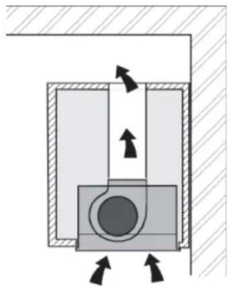
natural_image
Cross-sectional diagram of a mechanical or electrical component with directional arrows indicating flow or movement (no text or symbols)2
natural_image
Cross-sectional diagram of a mechanical or hydraulic system with directional arrows indicating flow or movement (no text or symbols present)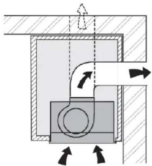
natural_image
Cross-sectional diagram of a mechanical or hydraulic system with directional arrows indicating flow or movement (no text or symbols present)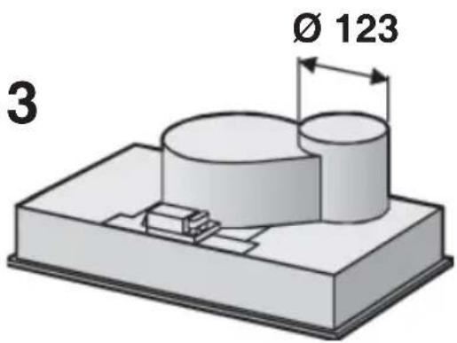
4
5
natural_image
Technical diagram of a structural support frame with vertical supports and diagonal braces (no text or symbols)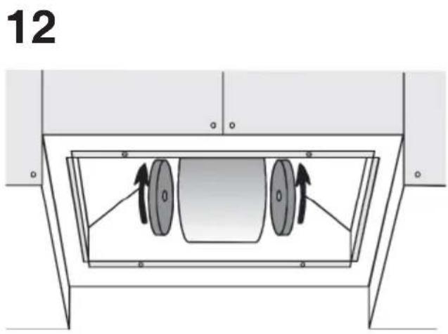
natural_image
Technical diagram of a mechanical or electrical enclosure with two circular components inside a frame (no text or symbols)14 15
natural_image
Technical line drawing of a mechanical component with a central circular housing (no text or symbols)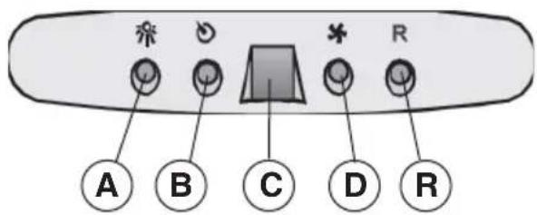
16
17
18
20
natural_image
Technical line drawing of a mechanical component with a magnified inset showing a circular feature (no text or symbols)21
22

- DESCRIPTION
- INSTALLATION
- INSTALLATION IN DUCTING VERSION:
- INSTALLATION IN FILTERING VERSION:
- OPERATION
- Controls shown in Fig. 16:
- AUTOMATIC OPERATION WITH SENSOR:
- Modification of sensor sensitivity: sensor sensitivity can be modified by operating as follows:
- Warning: in order to avoid damaging the sensor, never use silicone products near the hood!
- Removing the grease fi Iters:
- Lighting:
- CAUTION: Do not handle glass bulb with bare hands.
- MALFUNCTIONS
- • The hood is not working
- - The blower does not work but the lights do
- • The hood is not operating effectively
- For filtering hood
- • The lamp does not work
- Halogen lamps:
- - Remote control not working (where present)
Brand : BEST
Model : 07E00119B
Category : Range hood