
Party - Cooker Steel Cucine - Free user manual and instructions
Find the device manual for free Party Steel Cucine in PDF.
Frequently Asked Questions - Party Steel Cucine
Download the instructions for your Cooker in PDF format for free! Find your manual Party - Steel Cucine and take your electronic device back in hand. On this page are published all the documents necessary for the use of your device. Party by Steel Cucine.
USER MANUAL Party Steel Cucine
SCHEMA “A” SCHEMA “B” SCHEMA “C”
ALLACCIAMENTO ORIGINALE IMPOSTATO DAL COSTRUTTORE.
ALLACCIAMENTO ALLA MORSETTIERA
| MODELLO POTENZA KW ALIMENTAZIONE | ||
| CUCINA 5 FUOCHI (1 FORNO) | 2,9 | SCHEMA "C" |
| CUCINA 6 FUOCHI (1 FORNO) | 2,9 | |
| CUCINA PIANO INDUZIONE (1 FORNO) (6 ELEMENTI) | 10,1 | |
| CUCINA 6 FUOCHI (2 FORNI) | 3,9 | |
| CUCINA PIANO INDUZIONE (2 FORNI) (6 ELEMENTI) | 11,1 | |
I MODELLI COLLEGATI SECONDO LO SCHEMA “A” POSSONO ESSERE COMMUTATI DALL'INSTALLATORE SECONDO LO SCHEMA “B”.
I MODELLI COLLEGATI SECONDDO LO SCHEMA "C" POSSONO ESSERE COMMUTATI DALL'INSTALLATORE SECONDDO LO SCHEMA"A".
| AT | ● | ISO 228-1 |
| BE | ● | |
| CH | ● | |
| DE | ● | |
| DK | ● | |
| ES | ● | ● |
| FI | ● | ● |
| FR | ● | |
| GB | ● | |
| IE | ● | |
| IT | ● | ● |
| LU | ||
| NL | ● | |
| NO | ● | ● |
| PT | ● | ● |
| SE | ● | ● |
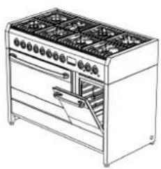
Thank you for choosing our product. From now on, cooking will always be pleasantly creative with your new cooker.
We recommend carefully reading all the instructions in this manual, which includes detailed information about the most suitable conditions for using the cooker correctly and safely. These instructions also help you to become familiar with each component.
Useful advice is given for using recipients, utensils, positions of guides and control settings.
The correct cleaning operations contained in this manual allow you to maintain the cooker's performance unchanged over time.
The individual sections are set out in order to allow you to become familiar with all the functions in the cooker. The text is easy to comprehend and is accompanied with detailed images and simple pictograms.
Reading this manual thoroughly will provide you with the answer to any question that may arise regarding the correct use of your new cooker.

INSTRUCTIONS FOR THE INSTALLER: for the qualified technician who is in charge of adequately checking the gas system, installing, commissioning and testing the appliance.

INSTRUCTIONS FOR THE USER: include suggestions, the description of the controls and the correct cleaning and maintenance operations for the appliance.
- General information 61
1.1 Technical service 61
2.Warnings for safety and use 62
3.Installation 64
3.1 General warnings 66
3.2 Replacing the adjustable feet 66
3.3 Fitting the front moulding (only available on certain models) 67
3.4 Fitting the backguard (only available on certain models) 67
3.5 Electric connection 68
3.6 Ventilation in rooms with gas appliances 71
3.7 Gas connection 72
3.8 Gas adjustments 75
3.9 Connecting to LPG 75
- Final operations 78
4.1 Levelling the cooker to the floor 78
5.Description of controls 79
5.1 The front panel 79
6.Using the cooking hob 90
6.1 Switching on the burners 90
6.2 Switching off the burners 90
6.3 Abnormal Operation 90
- Using the induction hob 91
7.1 General warnings 91
7.2 Automatic radiant power distribution 92
7.3 Energy regulator table 93
7.4 Switching on the induction hob for the first time 93
7.5 Pan recognition 94
7.6 Switching on a radiant element 95
7.7 Automatic switch-off 97
7.8 Switching off manually 97
7.9 Child safety 97
7.10 In the event of faults and failures 98
8.Using the ovens 99
8.1 General warnings 99
8.2 Storage drawer (only available on certain models) 99
8.3 Risk of condensation 99
8.4 Using the electric multifunction oven 100
8.5 Using the auxiliary oven with natural convection 102
9.Cooking suggestions 103
9.1 Suggestions for using the hob burners correctly 103
9.2 Suggestions for using the induction hob correctly 103
9.3 Suggestions for using the oven correctly 103
10. Cleaning and maintenance 106
10.1 Cleaning the stainless steel surfaces 106
10.2 Cleaning the enamelled surfaces 106
10.3 Cleaning the polished surfaces 106
10.4 Cleaning the wooden surfaces, accessories and parts 106
10.5 Cleaning the knobs and the control panel 106
10.6 Cleaning the grids and burners 107
10.7 Cleaning the igniter plugs and thermocouples 107
10.8 Cleaning the induction hob 107
10.9 Cleaning the oven 108
11.Special maintenance 109
11.1 Removing the oven door 109
11.2 Removing the side rack-holder frames 110
11.3 Removing and cleaning the inside oven fan 111
11.4 Replacing the oven light bulb 111
This user's manual is an integral part of the product purchased. The user must conserve the manual correctly so that it is always available for consultation during the use and maintenance of the product. Keep this user's manual for future reference. If the product is resold, the manual must be transferred to any subsequent owner or user of the product.
The manufacturer is not liable for any inaccuracies in this booklet resulting from printing or transcription errors. The manufacturer reserves the right to modify its products as it considers necessary or in the interests of the user, without compromising their essential safety and operating characteristics.
CLASSES OF APPLIANCES
The cooking appliances described in this operating manual belong to the following installation classes:
Class 1: non-flush-mounted cooking appliance;
- Class 2 - subclass 1: cooking appliance flush-mounted between two units, made up of a single unit, but which can also be installed so that the side walls are accessible.
1. General information
This product was manufactured in compliance with the following directives:
2006/95/EC relating to electrical equipment designed for use within certain voltage limits.
2004/108/EC relating to electromagnetic compatibility. In compliance with the provisions relating to electromagnetic compatibility, the electromagnetic induction hob belongs to group 2 and to class b (EN 55011).
2009/142/EC for "Gas Appliances".
- EC Regulation no. 1935 of 27/10/2004 on materials and articles intended to come into contact with food.
2011/65/EC (RoHS) on restricting the use of hazardous substances in manufacturing materials.
1.1 Technical service
Before leaving the factory, this appliance has been tested and set up by qualified, specialist personnel, so as to guarantee the best operating results. Each repair or adjustment that may subsequently be necessary must be carried out with the utmost care and attention. We therefore recommend always contacting the Dealer where the appliance was purchased or your nearest Service Centre, specifying the type of problem and the appliance model.

2.Warnings for safety and use

THIS MANUAL IS AN INTEGRAL PART OF THE APPLIANCE. IT SHOULD BE KEPT IN GOOD CONDITION AND CLOSE TO THE APPLIANCE FOR THE WHOLE LIFECYCLE OF THE COOKER. WE RECOMMEND READING THIS MANUAL VERY CAREFULLY BEFORE USING THE COOKER. IN CASE AN ADDITIONAL JETS KIT IS GIVEN AS ACCESSORY TO THE COOKER, WE RECOMMEND KEEPING AND PRESERVING IT. THE INSTALLATION MUST BE CARRIED OUT BY QUALIFIED PERSONNEL AND IN COMPLIANCE WITH CURRENT STANDARDS. THIS APPLIANCE IS FOR DOMESTIC USE AND CONFORMS TO THE EEC DIRECTIVES CURRENTLY IN FORCE. USE IN A PROFESSIONAL SETTING AND INSTALLATION WITHIN A BUSINESS SUCH AS RESTAURANT, BAR, COMPANY CANTEEN OR ANY OTHER USE OTHER THAN THAT SPECIFIED HERE WILL IMMEDIATELY VOID THE WARRANTY. THE APPLIANCE IS BUILT FOR CARRYING OUT THE FOLLOWING FUNCTION: COOKING AND HEATING FOOD; ANY OTHER USE IS TO BE CONSIDERED IMPROPER. THE MANUFACTURER DECLINES ANY RESPONSIBILITY SHOULD THE APPLIANCE BE USED FOR PURPOSES OTHER THAN THOSE INDicated.
AUS
THIS MANUAL IS AN INTEGRAL PART OF THE APPLIANCE. IT SHOULD BE KEPT IN GOOD CONDITION AND CLOSE TO THE APPLIANCE FOR THE WHOLE LIFECYCLE OF THE COOKER. WE RECOMMEND READING THIS MANUAL AND ALL THE INDICATIONS IT INCLUDES VERY CAREFULLY BEFORE USING THE COOKER. IN CASE AN ADDITIONAL JETS KIT IS GIVEN AS ACCESSORY TO THE COOKER, WE RECOMMEND KEEPING AND PRESERVING IT. THE INSTALLATION MUST BE CARRIED OUT BY AUTHISED PERSON AND IN COMPLIANCE WITH CURRENT REGULATIONS IN FORCE. THIS APPLIANCE IS ENVISAGED FOR DOMESTIC USE AND CONFORMS TO THE AUSTRALIAN STANDARDS CURRENTLY IN FORCE. USE IN A PROFESSIONAL SETTING AND INSTALLATION WITHIN A BUSINESS SUCH AS RESTAURANT, BAR, COMPANY CANTEEN OR ANY OTHER USE OTHER THAN THAT SPECIFIED HERE WILL IMMEDIATELY VOID THE WARRANTY. THE APPLIANCE IS BUILT FOR CARRYING OUT THE FOLLOWING FUNCTION: COOKING AND HEATING FOOD; ANY OTHER USE IS TO BE CONSIDERED IMPROPER. THE MANUFACTURER DECLINES ANY RESPONSIBILITY SHOULD THE APPLIANCE BE USED FOR PURPOSES OTHER THAN THOSE INDicated.
AT THE MOMENT OF PURCHASE, THE USER ASSUMES DIRECT RESPONSIBILITY FOR THE PRODUCT AND MUST THEREFORE MAKE SURE THAT, WITH NORMAL USE, NO INSTABILITY, DEFORMATION, BREAKAGE OR WEAR OCCURS OVER TIME THAT WOULD REDUCE PRODUCT SAFETY.
THIS PRODUCT IS DESIGNED AND MANUFACTURED TO OPERATE SAFELY AND DOES NOT POSE ANY DANGERS TO PEOPLE, ANIMALS, AND OBJECTS.
DO NOT MODIFY THIS APPLIANCE.
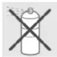
DO NOT SPRAY AEROSOLS IN THE VICINITY OF THIS APPLIANCE WHILE IT IS IN OPERATION.
WHERE THIS APPLIANCE IS INSTALLED IN MARINE CRAFT OR IN CARAVANS, IT SHALL NOT BE USED AS A SPACE HEATER.
DO NOT LEAVE ANY PIECES OF THE PACKING UNATTENDED IN THE HOME. SEPARATE THE VARIOUS PACKING MATERIALS AND DELIVER THEM TO THE NEAREST RECYCLING CENTRE.
THE EARTH CONNECTION IS OBLIGATORY CONFORMING TO THE MODALITIES ENVISAGED BY THE SAFETY STANDARDS OF THE ELECTRICAL WIRING SYSTEM.
SHOULD THE GAS TAPS BE DIFFICULT TO ROTATE, LUBRicate THEM USING A SPECIFIC PRODUCT FOR HIGH TEMPERATURES. CONTACT THE TECHNICAL SERVICE FOR THIS OPERATION.


IMMEDIATELY AFTER INSTALLATION, TEST THE APPLIANCE BRIEFLY BY FOLLOWING THE INSTRUCTIONS SHOWN BELOW. IN THE EVENT OF A MALFUNCTION, DISCONNECT THE APPLIANCE FROM THE MAINS AND CONTACT YOUR NEAREST TECHNICAL SERVICE CENTRE. DO NOT ATTEMPT TO REPAIR THE APPLIANCE.
USING A GAS COOKING APPLIANCE PRODUCES HEAT AND HUMIDITY IN THE ROOM WHERE IT IS INSTALLED. ENSURE GOOD ROOM VENTILATION: KEEP NATURAL VENTILATION GRILLES OPEN OR INSTALL A MECHANICAL VENTILATION DEVICE (DUCTED EXTRACTION HOOD). INTENSIVE AND PROLONGED APPLIANCE USE MAY REQUIRE SUPPLEMENTARY VENTILATION, FOR EXAMPLE, OPENING A WINDOW, MORE EFFECTIVE VENTILATION, OR INCREASING THE EXTRACTION HOOD POWER, IF INSTALLED.

EACH TIME YOU FINISH USING THE COOKING HOB, ALWAYS CHECK THAT THE CONTROL KNOBS ARE IN "ZERO" POSITION (OFF).
NEVER PUT INFLAMMABLE OBJECTS INTO THE OVEN: SHOULD IT BE ACCIDENTALLY SWITCHED ON, A FIRE MAY BREAK OUT. IN THE EVENT OF A FIRE: CLOSE THE MAIN GAS SUPPLY AND CUT OFF THE ELECTRIC CURRENT. DO NOT THROW WATER ON BURNING OR FRYING OIL. DO NOT STORE INFLAMMABLE OBJECTS OR AEROSOL CANS NEAR THE APPLIANCE AND DO NOT SPRAY NEAR THE BURNERS WHEN SWITCHED ON. DO NOT WEAR BAGGY CLOTHES OR ACCESSORIES THAT ARE NOT CLOSE TO THE BODY WHEN THE BURNERS ARE SWITCHED ON: SERIOUS INJURIES CAN BE CAUSED BY BURNING FABRIC. DO NOT USE OR STORE FLAMMABLE MATERIALS IN THE APPLIANCE STORAGE DRAWER OR NEAR THIS APPLIANCE.
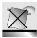
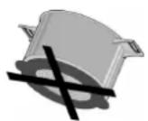
DO NOT REST SAUCEPANS THAT DO NOT HAVE A PERFECTLY SMOOTH, EVEN BASE ON THE COOKING HOB.
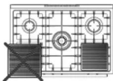
DO NOT USE RECIPIENTS OR STEAK GRILLS THAT EXCEED THE OUTER PERIMETER OF THE COOKING HOB.
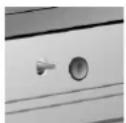
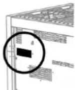
THE IDENTIFICATION PLATE WITH THE TECHNICAL DATA, SERIAL NUMBER AND THE MARK IS CLEARLY VISIBLE ON THE BACK OF THE APPLIANCE. A SECOND PLATE, INCLUDING DETAILED INFORMATION ABOUT THE MODEL AND SERIAL NUMBER, IS PLACED INSIDE THE EQUIPMENT ON THE LEFT SIDE AND IS VISIBLE ON OPENING THE OVEN DOOR.
THESE PLATES MUST NEVER BE REMOVED.
THE APPLIANCE SHOULD ONLY BE USED BY ADULTS. DO NOT ALLOW CHILDREN TO APPROACH OR PLAY WITH THE APPLIANCE. NEVER STORE ITEMS THAT CHILDREN MAY ATTEMPT TO REACH ABOVE THE APPLIANCE. THE HEATING UP OF SOME PARTS OF THE APPLIANCE AND OF THE USED PANS MAY BE A DANGER, SO DURING FUNCTIONING AND DURING ALL THE TIME NECESSARY FOR THE COOOLING DOWN, TAKE CARE TO POSITION THE HOT PANS IN A WAY TO PREVENT BURNS OR OVERTURNING. AVOID LEAVING THE OVEN DOOR OPEN DURING FUNCTIONING OR IMMEDIATELY SOON AFTER THE SWITCHING OFF. AVOID TOUCHING THE HEATING ELEMENTS INSIDE THE OVEN AND GRILLS AS WELL.
RESTING OR SITTING ON THE OPEN OVEN DOOR, DRAWERS OR STORAGE COMPARTMENT CAN OVERTURN THE APPLIANCE, AND CONSEQUENTLY CAUSE HARM. THE DRAWERS HAVE A DYNAMIC CAPACITY OF 25 KG.
IF THE COOKER IS SET ON A PEDESTAL, APPROPRIATE MEASURES MUST BE TAKEN TO PREVENT IT FROM SLIDING OFF THE PEDESTAL.

WHEN THE APPLIANCE IS DECOMMISSIONED, IT MUST BE DISPOSED OF IN A SUITABLE RECYCLING CENTRE. CUT OFF THE MAINS POWER CORD AFTER UNPLUGGING IT FROM THE WALL OUTLET, AND MAKE SAFE ANY COMPONENTS WHICH MIGHT BE DANGEROUS FOR CHILDREN (DOORS, ETC.).
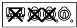
THIS APPLIANCE IS MARKED ACCORDING TO THE EUROPEAN DIRECTIVE 2002/96/EC ON WASTE ELECTRICAL AND ELECTRONIC EQUIPMENT (WEEE). BYENSURING THIS PRODUCT IS DISPOSED OF CORRECTLY, YOU WILL HELP PREVENT POTENTIAL NEGATIVE CONSEQUENCES FOR THE ENVIRONMENT AND HUMAN HEALTH, WHICH COULD OTHERWISE BE CAUSED BY INAPPROPRIATE WASTE HANDLING OF THIS PRODUCT.
THE SYMBOL ON THE PRODUCT, OR ON THE DOCUMENTS ACCOMPANYING THE PRODUCT, INDICATES THAT THIS APPLIANCE MAY NOT BE TREATED AS HOUSEHOLD WASTE. INSTEAD IT SHALL BE HANDED OVER TO THE APPLICABLE COLLECTION POINT FOR THE RECYCLING OF ELECTRICAL AND ELECTRONIC EQUIPMENT. DISPOSAL MUST BE CARRIED OUT IN ACCORDANCE WITH LOCAL ENVIRONMENTAL REGULATIONS FOR WASTE DISPOSAL. FOR MORE DETAILED INFORMATION ABOUT TREATMENT, RECOVERY AND RECYCLING OF THIS PRODUCT, PLEASE CONTACT YOUR LOCAL CITY OFFICE, YOUR HOUSEHOLD WASTE DISPOSAL SERVICE OR THE SHOP WHERE YOU PURCHASED THE PRODUCT.
The manufacturer declines any responsibility for damage incurred by persons or objects that is caused by not following the above guidelines or by tampering with any part of the appliance or by using non-original spare parts.
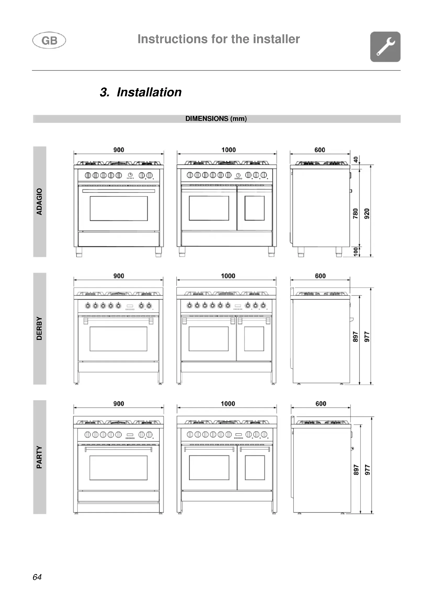
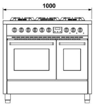
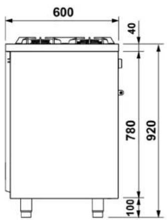
3. Installation
DIMENSIONS (mm)
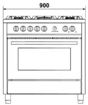
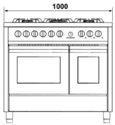
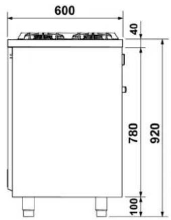
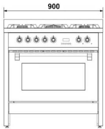
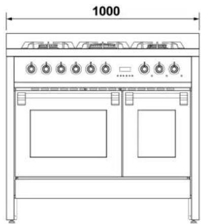
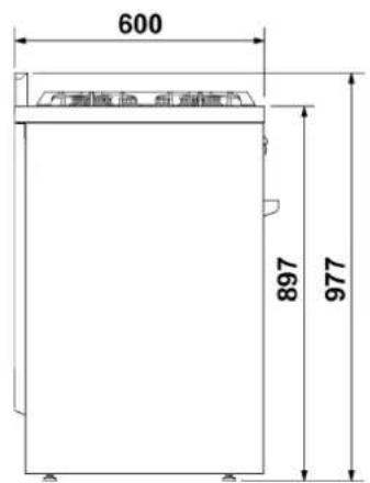
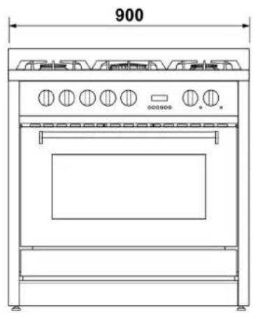
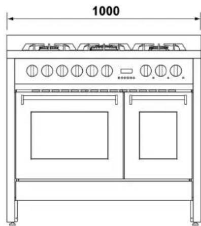
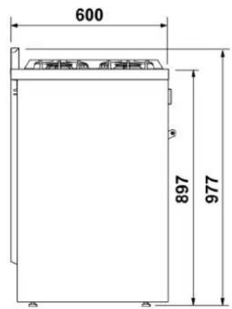
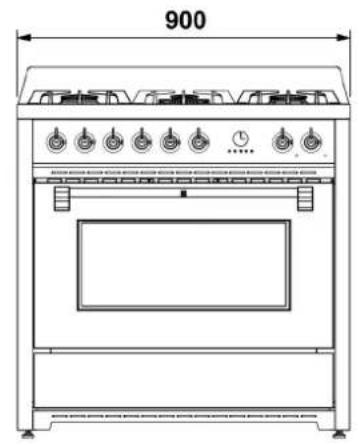
DIMENSIONS (mm)
OXFORD
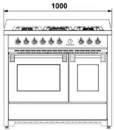
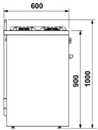
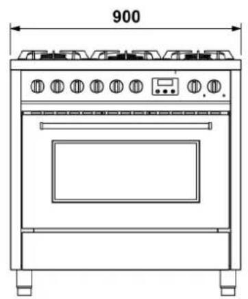
ENFASI
3.1 General warnings

The following operations must be carried out by a qualified installing technician. The installing technician is responsible for correctly installing the appliance according to current safety standards. Before using the appliance, remove the protective plastic on the control panel, stainless steel parts, etc...

This appliance shall be installed only by authorised personnel and in accordance with the manufacturer's installation instructions, local gas fitting regulations, municipal building codes, water supply regulations, electrical wiring regulations, AS 5601/AG 601 - Gas Installations and any other statutory regulations. Before using the appliance, remove the protective plastic on the control panel, stainless steel parts, etc...
The manufacturer declines any responsibility for damage incurred by persons, animals or objects that is caused by not following the above guidelines (cfr. chapter "2.Warnings for safety and use").
The technical data is indicated on the plate located on the back of the appliance. The adjustment conditions are shown on a label applied to the packing and the appliance.

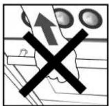
Do not use the oven door handle for lifting or handling, including while unpacking the appliance.
3.2 Replacing the adjustable feet
The cooker comes with standard feet, already installed.

The standard feet allow you to adjust the height so that you can level the cooker to the floor; the cooker becomes unstable if you unscrew them too much.
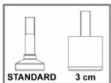
To raise the cooker, you should replace the standard feet with higher ones (supplied with some models or ordered from your retailer) for an extra 3 cm.

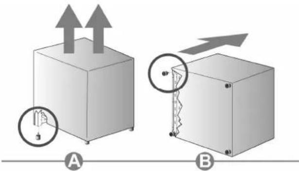
Before turning the cooker over, we recommend removing all the parts that are not stably attached to it, in particular the cooking hob grids and burners. To lighten the weight of the cooker, the accessories inside the oven may also be removed, thereby preventing accidental damage during the overturning operation.
Proceed in either of the following ways to replace the feet:
A Lifting the cooker off the floor.
B Laying the cooker on its back.
Remove the feet from the packing and screw them to the bottom of the cooker.
Make the final adjustment of the feet, to level the cooker to the floor, after completing the gas and electrical connections.

Should you need to drag the equipment, tighten the feet all the way and then adjust them after placing it where expected.

3.3 Fitting the front moulding (only available on certain models)
For some cooker models, a front moulding is available to complement its aesthetics.
Before turning the cooker over, we recommend removing all the parts that are not stably attached to it, in particular the cooking hob grids and burners. To lighten the weight of the cooker, the accessories inside the oven may also be removed, thereby preventing accidental damage during the overturning operation.
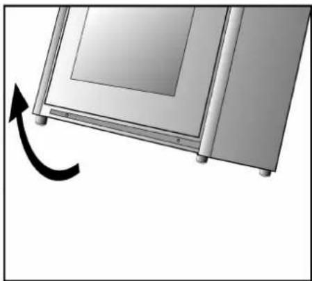
To assemble, proceed as follows:
-
tilt the cooker backwards;
-
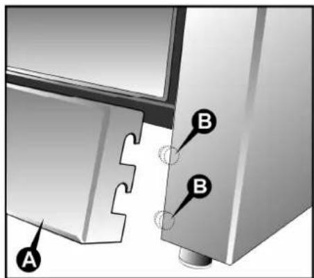
align the moulding A with the mounting position as shown in the illustration;
-
apply the moulding until it fits into the mounting position;
-
pull the moulding downward so that it hooks onto the 4 pins B (two on each side) present on the cooker.
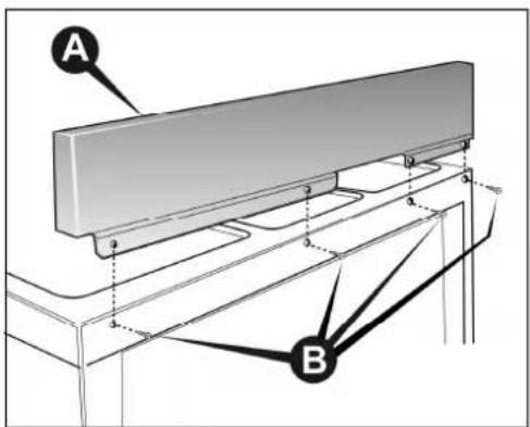
3.4 Fitting the backguard (only available on certain models)
Proceed as follows to install:
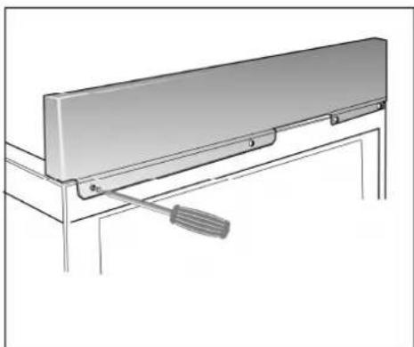
- rest the backguard A on the back of the surface, making sure the holes are aligned.
- tighten the 4 screws B using a Phillips screwdriver.

Any yellowing of the steel over time, which is completely natural, in no way alters its original characteristics. It can be removed using specific steel cleaning products.
3.5 Electric connection
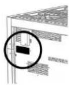
Make sure that the voltage and the size of the mains corresponds to the specifications shown on the plate located on the back of the appliance.
A second plate, including detailed information about the model and serial number, is placed inside the equipment on the left side and is visible on opening the oven door.
These plates must never be removed.
Prepare an omni-polar cutoff device on the power supply line of the appliance with a contact opening distance equal to or more than 3mm , located in a convenient position near the appliance.
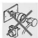
Do not use reducers, adapters or shunts.
Before making the electric connection, make sure of the efficiency of the earthing.
Make sure that the relief valve and the home wiring system are able to withstand the appliance load.
The yellow/green earth cable must not be subject to cutoffs.
The electric cable must not come into contact with parts whose temperature is more than 50^ higher than room temperature.
3.5.1 Electric power cable section
According to the type of power supply, use a cable that conforms to the following table.
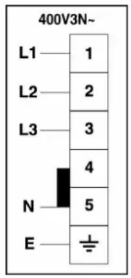
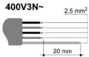
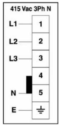
Running at 400V3N~ (models connected according to DIAGRAM "A"): use a pentapolar cable type H05RFF (cable measuring 5 × 2.5 mm²).
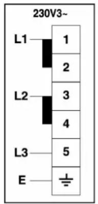
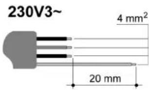
Running at 230V3~ (models connected according to DIAGRAM "C" but commuted by the installer according to DIAGRAM "B"): use a tetrapolar cable type H05RR-F (cable measuring 4 × 4 mm²).
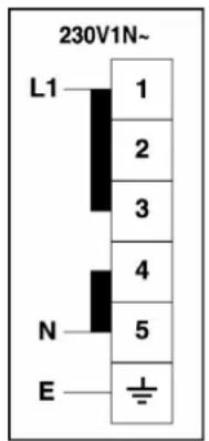
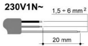
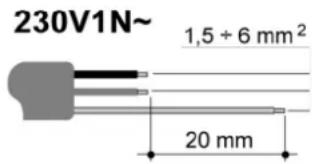
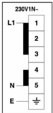
Running at 230V1N~ (models connected according to DIAGRAM "C"): up to 2.9kW use a tripolar cable type H05RR-F (cable measuring 3× 1.5mm^2 ); between 2.9kW and 5.4kW use a tripolar cable type H05RR-F (cable measuring 3× 2.5mm^2 ); between 5.4 kW and 7kW use a tripolar cable type H05RR-F (cable measuring 3× 4mm^2 ); over 7kW use a tripolar cable type H05RR-(cable measuring 3× 6mm^2 ).
The end to be connected to the appliance must have the earth wire (yellow-green) at least 20mm longer.
AUS
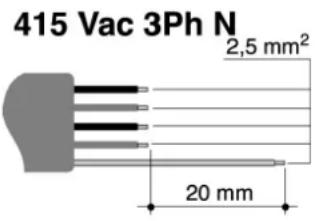
Running at 415 Vac 3Ph N (models connected according to DIAGRAM "A"): use a pentapolar cable type H05RR-F (cable measuring 5 × 2.5 mm^2 ).
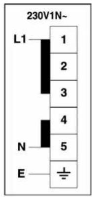
Running at 230V1N~ (models connected according to DIAGRAM "B"): up to 2.9kW use a tripolar cable type H05RR-F (cable measuring 3× 1.5mm^2 ); between 2.9kW and 5.4kW use a tripolar cable type H05RR-F (cable measuring 3× 2.5mm^2 ); between 5.4 kW and 7kW use a tripolar cable type H05RR-F (cable measuring 3× 4mm^2 ); over 7kW use a tripolar cable type H05RR-F (cable measuring 3× 6mm^2 ).
The end to be connected to the appliance must have t he earth wire (yellow-green) at least 20mm longer.
3.5.2 Type of power supply
It is possible to obtain different connections according to the voltage, simply by moving the unconnected cable ends on the terminal board as shown in the following diagrams.
According to the model, consult the table "CONNECTION TO THE TERMINAL BOARD".
DIAGRAM “A” DIAGRAM “B” DIAGRAM “C”
ORIGINAL CONNECTION SET BY MANUFACTURER.

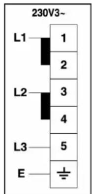
CONNECTION TO THE TERMINAL BOARD
| MODEL POWER KW POWER SUPPLY | ||
| COOKER 5 BURNERS (1 OVEN) | 2.9 | DIAGRAM “C” |
| COOKER 6 BURNERS (1 OVEN) | 2.9 | |
| COOKER INDUCTION HOB (1 OVEN) (6 ELEMENTS) | 10.1 | |
| COOKER 6 BURNERS (2 OVENS) | 3.9 | |
| COOKER INDUCTION HOB (2 OVENS) (6 ELEMENTS) | 11.1 | |
| MODELS CONNECTED ACCORDING TO DIAGRAM“A” CAN BE COMMUTATED BY THE INSTALLER ACCORDING TO DIAGRAM“B”. | ||
| MODELS CONNECTED ACCORDING TO DIAGRAM“C” CAN BE COMMUTATED BY THE INSTALLER ACCORDING TO DIAGRAM“A”. | ||
AUS
DIAGRAM “A” DIAGRAM “B”
AUS
CONNECTION TO THE TERMINAL BOARD
| MODEL | POWER kW | CURRENT DRAW (amps) |
| COOKER 5 BURNERS (1 OVEN) 2.9 12 | ||
| COOKER 6 BURNERS (1 OVEN) 2.9 12 | ||
| COOKER INDUCTION HOB (1 OVEN) (6 ELEMENTS) 10.1 42 | ||
| COOKER 6 BURNERS (2 Ovens) 3.9 16 | ||
| COOKER INDUCTION HOB (2 Ovens) (6 ELEMENTS) 11.1 42 |
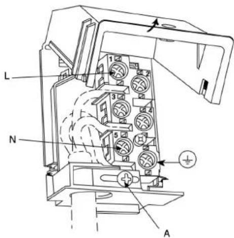
3.5.3 Replacing the electric cable
To replace the electric cable, it is necessary to access the terminal board. It is located on the back of the appliance as shown in the figure.
To replace the cable, proceed as follows:
open the terminal board box;
- unscrew the screw A that locks the cable;
- loosen the screw contacts and replace the cable with one of the same length that corresponds to the specifications in the table in section "3.5.1 Electric power cable section";
- the "yellow-green" earth wire must be connected to the terminal and must be approximately 20mm longer than the line cables;
- the neutral "blue" wire must be connected to the terminal marked with the letter N;
the line wire must be connected to the terminal marked with the letter L.


3.6 Ventilation in rooms with gas appliances
This appliance is not connected to an exhaust device for products of combustion. It must therefore be installed and connected in compliance with current installation standards. Pay particular attention to standards applied to room aeration.
This appliance is not connected to an exhaust device for products of combustion. Ventilation must be in accordance with AS5601/AG 601 - Gas Installations. In general, the appliance should have adequate ventilation for complete combustion of gas, proper flueing and to maintain temperature of immediate surroundings within safe limits. Pay particular attention to standards applied to room aeration.
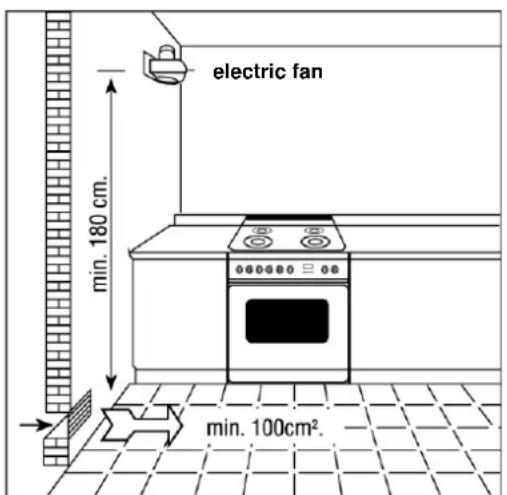
This appliance can only be installed in ventilated rooms, according to current standards, so as to allow, with openings onto external walls or appropriate ducts, for correct natural or forced ventilation that permanently and sufficiently ensures both the air intake necessary for correct combustion and the expelling of vitiated air. It is recommended that the appliance have a rangehood fitted directly above or ceiling fan in close proximity to the appliance.

Using a gas cooking appliance produces heat and humidity in the room where it is installed. Ensure good room ventilation: keep natural ventilation grilles open or install a mechanical ventilation device (ducted extraction hood).
Intensive and prolonged appliance use may require supplementary ventilation, for example, opening a window, more effective ventilation, or increasing the extraction hood power, if installed.
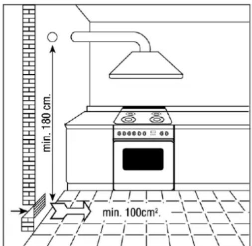
If this is the only gas appliance in the room, it is necessary to install a hood so as to expel vitiated air naturally and directly, with a rectilinear vertical duct at least twice as long as its diameter and having a minimum section of at least 100cm^2
For the essential air intake into the room, it is necessary to prepare a similar opening of at least 100cm^2 that communicates directly outside, situated close to floor level so as not to be obstructed from either inside or outside and so as not to disturb the combustion of the burners and the correct expelling of vitiated air and with a height difference from the exit opening of at least 180~cm .
Remember that the quantity of air necessary for combustion must not be lower than 2m^3 / h per kW of power (see total power in kW shown on the appliance plate).
In all other cases, i.e. when other gas appliances are present in the same room, or, if it is not possible to have natural direct ventilation, it is necessary to create natural, indirect ventilation or forced ventilation: for this type of operation, it is necessary to contact a qualified technician for installing and creating the ventilation system in strict compliance with the guidelines set out in current standards.
The openings should be positioned so as not to allow the formation of any unpleasant air current for the occupants. Furthermore, it is forbidden to use flues already used by other appliances to expel products of combustion.

3.7 Gas connection

The appliance's setting conditions are stated on the plate on the back of the appliance.
Gas-powered devices for home use, which are not connected to a conduit for the evacuation of combustion products, must not cause a concentration of carbon monoxide that could pose a health risk to the persons exposed in relation to the time of exposure.
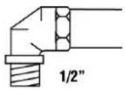
We recommend checking that the appliance is properly set up for the type of gas distributed. The connection to the gas pipes must be made in a workmanlike manner, in compliance with current standards that prescribe the installation of a safety tap at the end of the pipe. The threaded 12 gas connection pipe is located at the rear on the right hand side of the appliance.

We recommend checking that the appliance is properly set up for the type of gas distributed. The connection to the gas pipes must be made in a workmanlike manner, in compliance with current standards that prescribe the installation of a safety tap at the end of the pipe. The Gas Connection is male 12 BSP and is situated at the left hand, top rear of the appliance, 74mm from the side and 700mm from the floor (cookers) or 25mm from the underside (cooktops). The appliance is factory set for Natural gas. The test point pressure should be adjusted to 1.00kPa with the Wok and Semi-Rapid burners operating at maximum on 120cm models and the Wok burner operating at maximum on 90cm models.
For butane and propane, a pressure reducer conforming to standards regulations in force should be prepared. The seals must conform to standards regulations in force. Once the gas has been connected, check the seal of the unions with a soap and water solution.

For propane a pressure regulator set to provide a supply pressure of 2.75kPa conforming to standards regulations in force should be fitted. The seals must conform to standards regulations in force. Fit the test point assembly supplied with the appliance to the gas connection when installing for use with Propane Gas. Once the gas has been connected, check the seal of the unions with a soap and water solution.

It is possible to connect the gas in the following ways:
- using iron or copper rigid pipe as specified in AS5601 table 3.1;
-
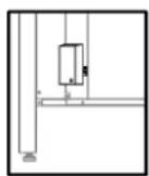
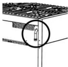
using a Plumbezy flexible hose, AGA approval number 6196, 10mm ID, class D and between 1 - 1.2m long in accordance with AG601 for a "high level connection". For cookers supplied with a flexible hose the restraining chain fitted to the rear of the cooker must be fixed to the wall as follows.
-
Supply fixing points on either side of the cooker (vertically in line with the chains attached) at approximately 100mm above floor level.
- Firmly secure the chains at these points.
- Supply similar fixing points at approximately 700mm above floor level using open hooks.
- Loop the chains over these hooks to prevent the cooker from accidentally tilting.
- Removing the chains from the hooks enables the cooker to be pulled out for service. Ensure that the chains prevent stress on the hose assembly while the cooker is in this position.
| AT | ● | ISO 228-1 |
| BE | ● | |
| CH | ● | |
| DE | ● | |
| DK | ● | |
| ES | ● | ● |
| FI | ● | ● |
| FR | ● | |
| GB | ● | |
| IE | ● | |
| IT | ● | ● |
| LU | ||
| NL | ● | |
| NO | ● | ● |
| PT | ● | ● |
| SE | ● | ● |
It is possible to connect the gas in the following ways:
- using iron or copper rigid pipe;
- using uninterrupted stainless steel flexible pipe with a mechanical fitting conforming to standards regulations in force (maximum length of extended pipe 2000 mm). The pipe should be connected straight to the elbow of the ramp;
- by inserting a flexible rubber pipe conforming to standards regulations in force. This pipe should be coupled straight to the rubber-holder P corresponding to the gas used, and locked with a clamp F conforming to standards regulations in force. In the latter case, check the expiry date printed on the pipe and replace it before that date.
| LPG NATURAL GAS |
| F-P |
Using flexible rubber pipes with a max. length of 1500mm
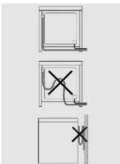
- do not allow the pipes to be constricted or crushed;
- pipes must not be subject to tractive force or torsional stress;
- do not allow the pipes to come into contact with cutting or sharp edges, etc...
- do not allow the pipes to come into contact with parts that can reach temperatures of 70^ above room temperature;
- make sure the entire length of the pipes can be inspected;
- do not use the Natural Gas Regulator supplied with the appliance for Propane Gas.

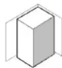
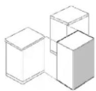
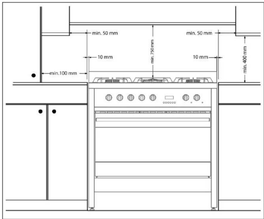
The unit must be coated in heat-resistant material (minimum 90^ . If the appliance is installed close to other units, the minimum space suggested in the following diagram must be left.
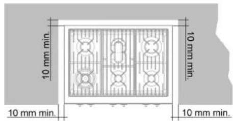

Any adjoining wall surface situated within 200mm from the edge of any hob burner must be a suitable non-combustible material for a height of 150mm for the entire length of the hob. Any combustible construction above the hotplate must be at least 600mm above the top of the burner and no construction shall be within 450mm above the top of the burner.
Where the distance from the edge of any burner to a horizontal surface is less than 200mm , the surface must be either: 10mm (min) below the level of the hob, or have the vertical component of the surface suitably covered with a non-combustible material as specified in AS 5601 - AG 601.
3.8 Gas adjustments
The injectors not supplied with the appliance should be requested from the Service Centre.

If the cooking appliance is set up for a different type of gas than that available, its injectors must be replaced, the minimum flow regulated and the rubber-holder changed. In order to replace the injectors in the cooking hob, it is necessary to carry out the following operations:

For cooktops, the Data Label is located on the underside of the appliance. A duplicate label is supplied to adhere in an accessible area adjacent to the appliance. For cookers, the label is situated in the appliance drawer. This appliance is suitable for Natural Gas and Propane; ensure that the available gas supply matches the Data Label.
If the cooking appliance is set up for a different type of gas than that available, its injectors must be replaced, the minimum flow regulated and the rubber-holder changed. In order to replace the injectors in the cooking hob, it is necessary to carry out the following operations:
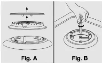
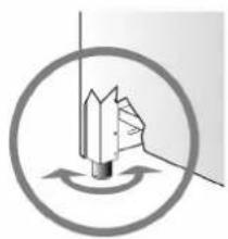
- remove the pan supports;
- remove the burners and burner caps (Fig. A);
- take out the injector (Fig. B) and replace it with one suitable for the new type of gas (see "G ENERAL INJECTORS TABLE" on page 76-77);
- replace the gas label (on the rear of the appliance) with the new one provided with the injectors kit;
- refit all parts by following the disassembly instructions in reverse order and taking care to position the burner cap correctly on the burner.
3.8.1 Minimum flow of valved cooking hob taps
- Switch on the burner and turn the control knob towards the minimum flow position
- remove the knob;
- using a screwdriver, adjust the internal screw Z until the correct low flame is obtained;
- refit the knob.
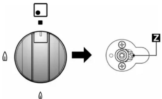

- Unscrew the adjustment screw Z to increase the flow, or tighten it to reduce the flow.
The adjustment is correct when the low flame measures approximately 3 or 4mm - For butane/propane, the adjustment screw should be tightened all the way.
- When changing quickly from maximum to minimum flow and vice versa make sure that the flame does not go out.

3.9 Connecting to LPG
Gas may only be connected to a gas installation, whether bottle supplied or other.

Gas may only be connected to a gas installation, whether bottle supplied or other.
When converting from Natural Gas to Propane ensure that the NG regulator is removed and replaced with the Test Point Assembly. A gas regulator suitable for a supply pressure of 2.75kPa should be part of the gas tank supply and should be adjusted with the Wok burner operating at maximum. Replace the old data plate with one which is suitable for the type of gas for which the appliance has been regulated.
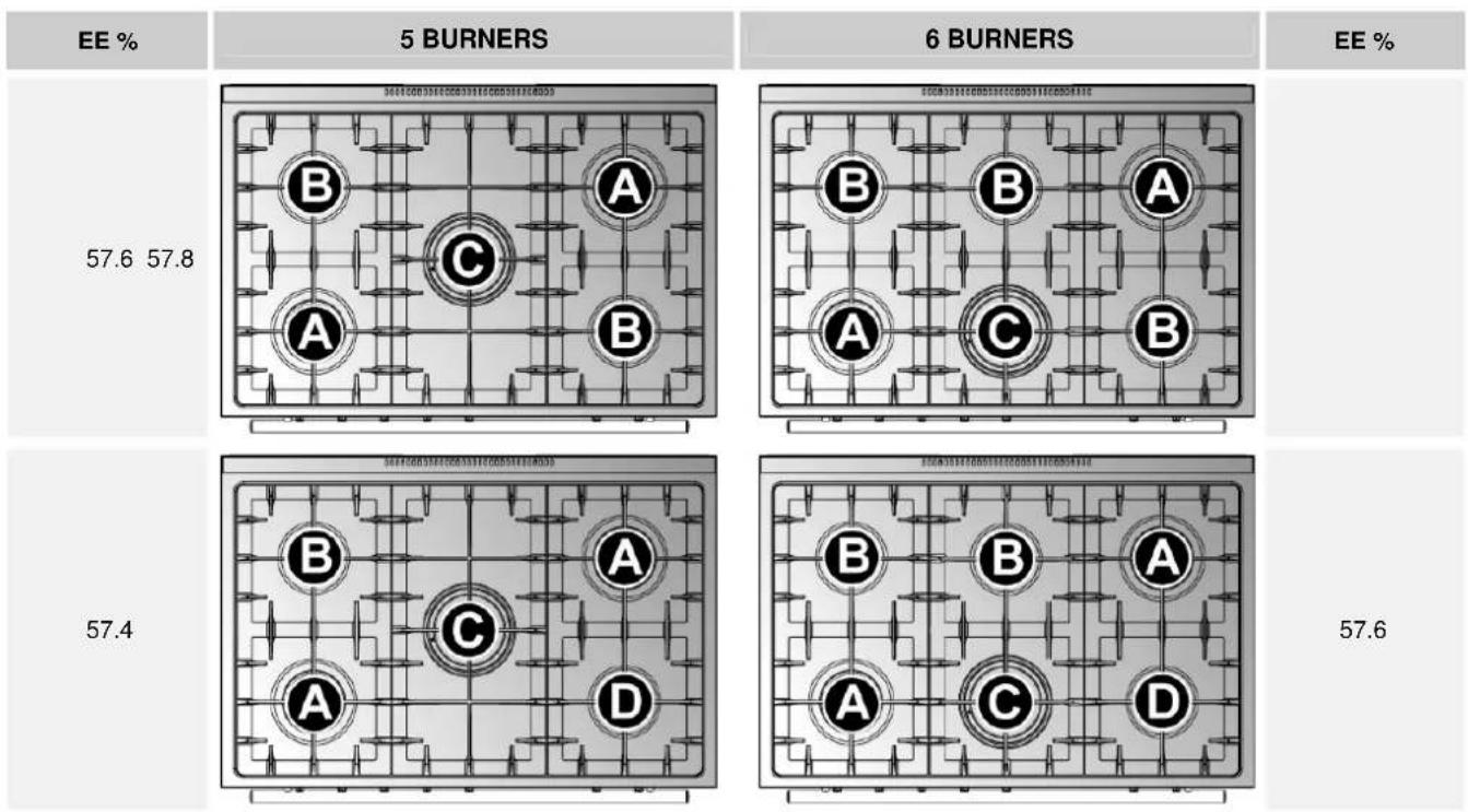
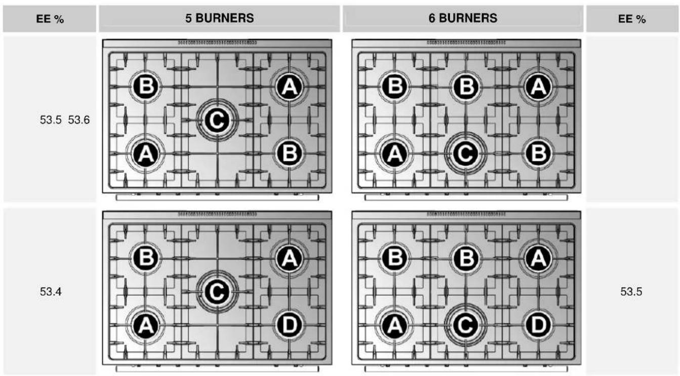
| GENERAL INJECTORS TABLE (ALUMINUM) | ||||||
| TYPE OF GAS | mbar | NOZZLE NO. | BURNERS POSITION TYPE MAX. | POWER Watt CONSUMPTION EE | ||
| MAX. MIN. | % | |||||
| G20 NATURAL GAS | 20 | 115 RAPID (A) 3000 750 286 l/h 58.9 | ||||
| 97 SEMI RAPID (B) 1750 480 167 l/h 58.7 | ||||||
| 128 TRIPLE-RING (C) 3500 1400 333 l/h 52.9 | ||||||
| 72 | AUXILIARY (D) | 1000 | 330 | 95 l/h | ||
| LPG BUTANE G30 PROpane G31 | 30 | 85 | RAPID (A) 3000 | 750 | 219 g/h | 58.9 |
| 28 | 65 SEMI RAPID (B) 1750 480 | 128 g/h | 58.7 | |||
| 37 | 96 TRIPLE-RING (C) 3500 1400 | 254 g/h | 52.9 | |||
| 50 | AUXILIARY (D) | 1000 | 330 | 73 g/h | ||

| GENERAL INJECTORS TABLE (ALUMINUM) | ||||
| TYPE OF GAS | kPa | NOZZLE NO. | BURNERS POSITION TYPE | MAX. CONSUMPTION |
| MJ | ||||
| NATURAL GAS | 1.00 | 1.50 | RAPID (A) | 11.50 |
| 1.20 | SEMI RAPID (B) | 6.90 | ||
| 1.65 | TRIPLE-RING (C) | 13.00 | ||
| 0.90 | AUXILIARY (D) | 3.90 | ||
| ULPG 2.75 | 0.95 | RAPID (A) | 11.50 | |
| 0.73 | SEMI RAPID (B) | 6.90 | ||
| 1.00 | TRIPLE-RING (C) | 13.00 | ||
| 0.53 | AUXILIARY (D) | 3.90 | ||

GENERAL INJECTORS TABLE (BRASS)
| TYPE OF GAS | mbar | NOZZLE NO. | BURNERS POSITION TYPE MAX. | POWER Watt CONSUMPTION EE | ||
| MIN. MAX. % | ||||||
| G20 NATURAL GAS | 20 | 115 RAPID (A) 3000 750 286 l/h 53.8 | ||||
| 97 SEMI RAPID (B) 1750 480 167 l/h 54 | ||||||
| 132 TRIPLE-RING (C) 3500 1800 | 333 l/h 52.3 | |||||
| 72 | AUXILIARY (D) | 1000 | 330 | 95 l/h | ||
| LPG BUTANE G30 PROPANE G31 | 30 | 85 | RAPID (A) 3000 | 750 | 219 g/h | 53.8 |
| 28 | 65 | SEMI RAPID (B) 1750 480 | 128 g/h 54 | |||
| 37 | 94 | TRIPLE-RING (C) 3500 1800 | 254 g/h | 52.3 | ||
| 50 | AUXILIARY (D) | 1000 | 330 | 73 g/h | ||
GENERAL INJECTORS TABLE (BRASS)
| TYPE OF GAS | kPa | NOZZLE NO. | BURNERS POSITION TYPE | MAX. CONSUMPTION |
| MJ | ||||
| NATURAL GAS | 1.00 | 1.50 | RAPID (A) | 11.50 |
| 1.20 | SEMI RAPID (B) | 6.90 | ||
| 1.65 | TRIPLE-RING (C) | 13.00 | ||
| 0.90 | AUXILIARY (D) | 3.90 | ||
| ULPG 2.75 | 0.95 | RAPID (A) | 11.50 | |
| 0.73 | SEMI RAPID (B) | 6.90 | ||
| 1.00 | TRIPLE-RING (C) | 13.00 | ||
| 0.53 | AUXILIARY (D) | 3.90 |
4. Final operations
4.1 Levelling the cooker to the floor
After having made the electrical and gas hook-ups, level the cooker to the floor using the adjustable feet that were previously screwed onto the bottom of the cooker.

Should it be necessary to drag the cooker, screw the feet in completely and carry out the final regulation only when the other operations are completed.

Check all connections for gas leaks with soap and water. DO NOT use a naked flame for detecting leaks. Ignite all burners to ensure correct operation of gas valves, burners and ignition. Turn gas taps to low flame position and observe stability of the flame. When satisfied with the hotplate, please instruct the user on the correct method of operation. In case the appliance fails to operate correctly after all checks have been carried out, refer to the authorised service provider in your area.
5. Description of controls
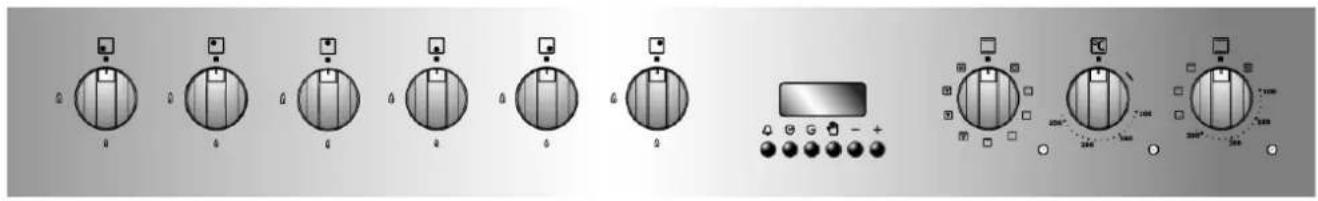
5.1 The front panel
All the commands and controls for the cooking hob and oven are on the front panel.
THE CONTROL PANEL
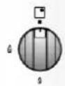
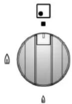
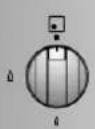
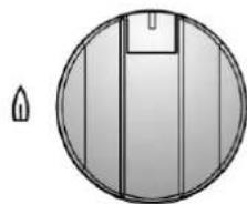
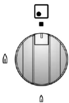
DESCRIPTION OF HOB BURNER KNOB
The flame is lit by simultaneously pressing and turning the knob anticlockwise to the low flame symbol
To regulate the flow of the flame, turn the knob to between the maximum and minimum settings. Turn off the burner by returning the knob to position

LAYOUT OF BURNERS - Description of symbols

FRONT LEFT

FRONT RIGHT

REAR LEFT

REAR RIGHT

CENTRE

REAR CENTRE

FRONT CENTRE
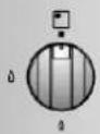
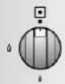
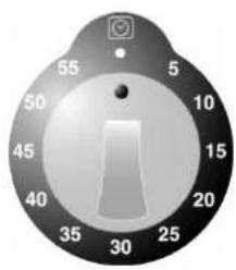
DESCRIPTION OF TIMER KNOB
Turn the knob all the way clockwise to wind the timer. It is possible to set the required time up to a maximum of 60 min. The bell rings briefly when the preset time has elapsed.
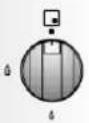
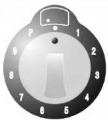
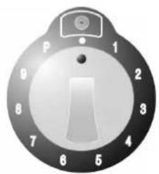
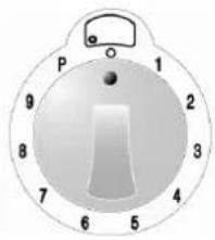
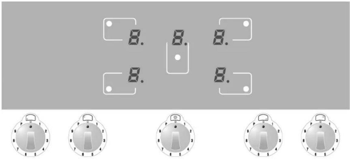
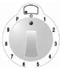
DESCRIPTION OF KNOBS ON THE INDUCTION HOB
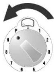
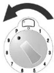
The induction hob is fitted with knobs for controlling the power level.
To select a different power level, turn the control knob to the required value (1 - 9 and P).
P is the maximum power applicable to each radiant element.
Each time the power level is changed, the display shows the value selected on the knob.
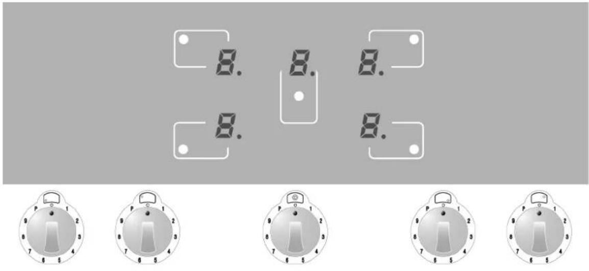
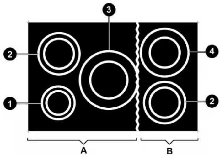
LAYOUT OF RADIANT ELEMENTS - Description of symbols

REAR LEFT

REAR RIGHT

FRONT LEFT

FRONT RIGHT

CENTRAL
All the controls for the radiant elements are located on the front panel and the relative displays are visible on the hob.
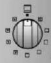
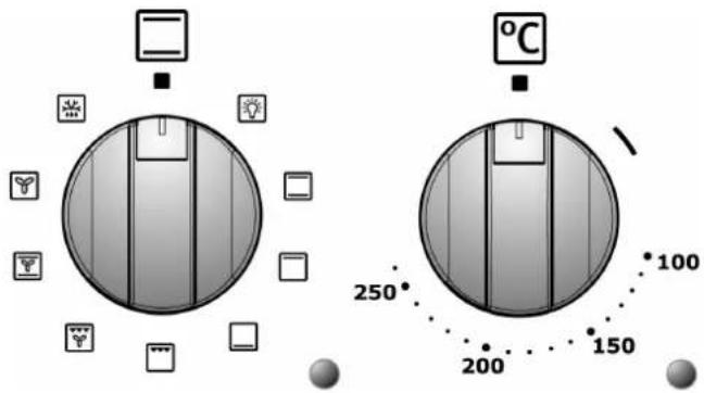
DESCRIPTION OF ELECTRIC OVEN KNOBS
The electric oven is controlled by two knobs: function switch knob and thermostat knob. They allow you to choose the most suitable type of heating for different cooking requirements, by switching on the heating elementents appropriately and setting the required temperature.
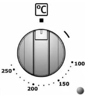
The setting on the thermostat knob operates the oven fan.
Below the oven knobs there are two warning lights: the green light signals the oven is working; the orange light indicates that the preset temperature has been reached. The orange light switches on and off to indicate when the heating automatically kicks in to maintain the temperature inside the oven at the level set on the thermostat knob.
The oven has an internal light. The light is always on while the oven is working: it can be switched on while the oven is off, for cleaning purposes, by turning the function switch knob to the symbol
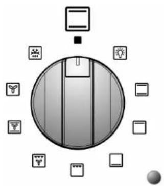
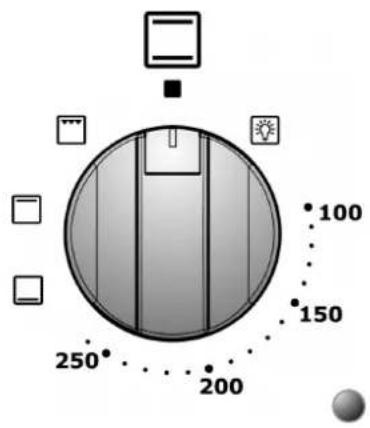
DESCRIPTION OF SYMBOLS ON THE FUNCTION SWITCH KNOB

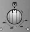
Some cooker models are equipped with an auxiliary electric oven with natural convection, controlled by a single knob. This allows the user to choose the most suitable type of heating for different cooking requirements, by switching on the heating elements appropriately and setting the required temperature. Using the same knob it is also possible to set the functions described in the table.
Below the auxiliary oven knob there is an orange light, which indicates when the oven has reached the set temperature. The orange light switches on and off to indicate when the heating automatically kicks in to maintain the temperature inside the auxiliary oven at the level set on the control knob.
The auxiliary oven has an internal light. The light is always on while the oven is working: it can be switched on while the oven is off, for cleaning purposes, by turning the function switch knob to the symbol
DESCRIPTION OF SYMBOLS ON AUXILIARY ELECTRIC OVEN KNOB

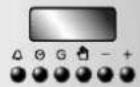
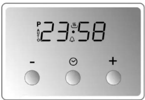
USING AND PROGRAMMING THE DIGITAL CLOCK ON OVENS
The end of cooking display electronically checks the operation of the oven. Programming the display allows the user to set the oven to switch on and off at set times.
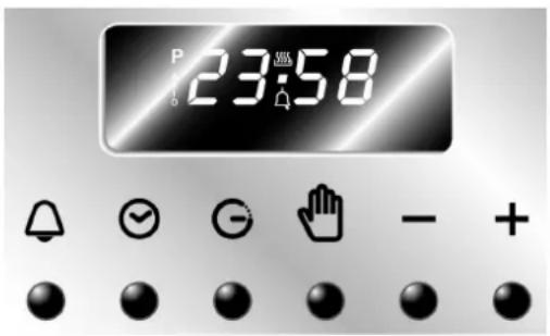
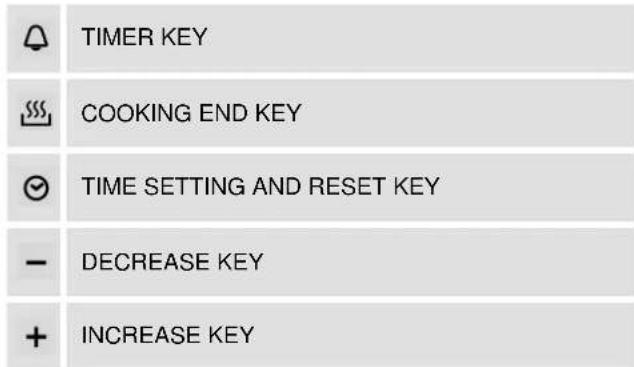
TIMER BUTTON
COOKING TIME BUTTON
END OF COOKING BUTTON
MANUAL OPERATION BUTTON
- DECREASE VALUE BUTTON
+ INCREASEVALUEBUTTON
SETTING THE TIME
When using the oven for the first time, or after a power cut, the display flashes regularly indicating 0:00
Press button to stop the flashing. Press the value variation buttons - or + within 5 seconds to increase or decrease by one minute at a time. Press one of the two value variation buttons until the current time appears.
Before setting the end of cooking display, it is necessary to select the required function and temperature. The function P is not enabled.
SEMI-AUTOMATIC COOKING
This setting automatically switches off the oven at the end of the cooking.
Press button and the display lights up showing the figures ; hold down and press at the same time the value variation buttons or to set the cooking time.
Release the button 品 begin the count of the programmed cooking time and the display shows the current time together with symbols AUTO and
AUTOMATIC COOKING
This setting switches the oven on and off automatically.
Press button and the display lights up showing the figures ; hold down and press at the same time the value variation buttons or to set the cooking time.
Press button to display the sum of the current time plus the cooking time: hold down and press at the same time the value variation buttons or to set the end of cooking time.
Release the button Go to begin the programmed count and the display shows the current time together with symbols AUTO and
After the setting, press button to see the remaining cooking time. Press button to see the end of cooking time.
END OF COOKING
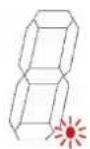
At the end of the cooking, the oven switches off automatically and at the same time an intermittent bell rings. After deactivating the bell, the display once again shows the current time together with symbol, which signals the oven has returned to manual conditions.


ADJUSTING THE VOLUME OF THE BELL
The volume of the bell can be varied (on 3 levels) while it is operating by pressing button .
DEACTIVATING THE BELL
The bell automatically stops ringing after seven minutes. It is possible to deactivate it manually by pressing button

After pressing button the oven begins to operate once again: to switch it off, turn the function switch knob and the thermostat knob to
It is also possible to deactivate the bell by pressing any one of the function buttons. The oven switches off regardless of the function or set temperature and the AUTO symbol flashes. To stop the AUTO symbol flashing, press button , turn the function selector switch and thermostat to
TIMER
The end of cooking display can also be used as a simple timer.

Using the display as a timer does not interrupt the operation of the oven at the end of the set time.

Press button and the display shows the figures ; hold down and press at the same time the value variation buttons or . Release the button to begin the programmed count and the display shows symbols and .

After programming the timer, the display once more shows the current time. To display the time remaining, press button
Setting inconsistent values is logically prevented (e.g. the end of cooking display does not accept a contrast between an end of cooking time and a longer cooking time).
DELETING SET DATA
With the program set, hold down the button of the function you wish to delete while at the same time reaching value with the value variation buttons or. Deleting the cooking time is interpreted by the display as the end of the cooking.
MODIFYING SET DATA
The data set for cooking can be modified at any moment by holding down the button of the function and at the same time pressing the value variation buttons or . +
USING AND PROGRAMMING THE DIGITAL CLOCK ON TOUCH SCREEN OVENS
The digital clock enables the oven to be set to automatically switch on and off.
| - | DECREASE KEY |
| ◎ | MODE KEY |
| + | INCREASE KEY |

This programmer works like a touch screen; rest the tip of the finger on the key for a few seconds to activate it.
INITIAL POWER-ON AND SETTING THE TIME
When first powering on the appliance or following a power failure, and the word AUTO flash on the display. Touch the "Mode" key to stop the flashing and use the + / - keys to set the time (hold down the keys to scroll rapidly).
To adjust the time under normal operating conditions, i.e. when the clock is already on, touch both keys + / - simultaneously for at least two seconds and then set the time as described previously.
MANUAL USE

This function is for using the oven without any programming.
It is always possible to switch from a programmed function to "Manuale" (Manual) function, by touching the "Mode" key; choose "Manuale" if no cooking programmes are to be used.

PROGRAMMING THE TIMER
This function activates an audible alarm after a preset time, without interfering with the operation of the oven.
The digital clock can also be used as a timer:
- touch the "Mode" key for at least 2 seconds to enter the programming menu; the flashing symbol will appear;
- use the keys to set the required time and the display will show the time remaining. The timer starts automatically and the symbol will stop flashing. When the set time is reached, an audible alarm sounds for 7 minutes and the symbol will flash;
- touch any key to stop the alarm or the "Mode" key to delete the programme.
PROGRAMMING THE COOKING DURATION

This function is for programming the cooking duration after which the oven switches off automatically.
- Set the required cooking function and temperature using the control knobs;
- touch the "Mode" key to enter the programming menu, touch again and the word "Dur" appears;
- use the + / - keys to set the cooking duration. The word "Auto" flashes for the duration of the programming phase. After 7 seconds the cooking programme starts and the symbol appears, while the word "Auto" stops flashing.
At the end of the set cooking time, an audible alarm sounds for 7 minutes, and the symbol AUTO will flash and symbol will turn off, switching the oven off automatically;
- touch any key to stop the alarm or the "Mode" key to delete the programme.
PROGRAMMING THE COOKING DURATION AND COOKING END

This function is for programming the oven to switch on at a set time and switch off automatically after cooking.
- Set the required cooking function and temperature using the control knobs;
- touch the "Mode" key to enter the programming menu, touch again and the word "Dur" appears;
- use the / keys to set the cooking duration;
- touch the "Mode" key to display "end", use the + / - keys to set the cooking end time. The word "Auto" flashes for the duration of the programming phase. After 7 seconds the programme exits the menu and the word "Auto" stops flashing. When the cooking start time is reached, the symbol appears and the oven switches on automatically.
At the end of the set cooking time, an audible alarm sounds for 7 minutes, and the symbol AUTO will flash and symbol 山 will turn off, switching the oven off automatically;
- touch any key to stop the alarm or the "Mode" key to delete the programme.
BEEPER
At the end of each preset function, an audible alarm sounds which turns off automatically after 7 minutes; touch the Mode" key to turn the beeper off immediately.
Three different types of audible alarm are available on the appliance; to choose between them, touch the + / - keys simultaneously, then touch the "Mode" key until "Tone" appears, then choose the required tone by touching the key.
USING AND PROGRAMMING THE DIGITAL ANALOGUE CLOCK ON OVENS
The digital clock enables the oven to be set to automatically switch on and off.
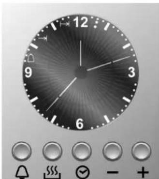
INITIAL POWER-ON AND SETTING THE TIME
When first powering on the appliance or following a power failure the display flashes. Press the key to stop the flashing and use the +/ - keys to set the time (hold down the +/ - keys to scroll rapidly).
MANUAL USE
This function is for using the oven without any programming.
It is always possible to switch from a programmed function to "Manuale" (Manual) function, by pressing the key; choose "Manuale" if no cooking programmes are to be used.
PROGRAMMING THE TIMER
This function activates an audible alarm after a preset time, without interfering with the operation of the oven.
The digital analogue clock can also be used as a timer:
- press the key and the display will light up as shown in Fig. 1;
- use the / keys to set the required time; the display will illuminate one segment for each minute set (Fig. 2 shows a cooking time of 10 minutes).
The timer starts automatically and the symbol will stop flashing. After a few seconds the display returns to clock function;
- press to display the time remaining. When the set time is reached, an audible alarm sounds for 7 minutes and the symbol will flash;
- press the key to reset the programme.
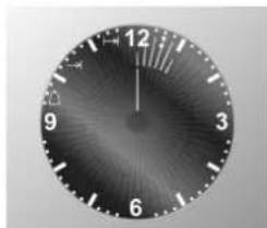
Fig. 1
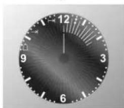
Fig. 2
PROGRAMMING THE COOKING DURATION
This function is for programming the cooking duration after which the oven switches off automatically.

- Set the required cooking function and temperature using the control knobs;
- press the key to enter the programming menu; the display will light up as shown in Fig. 3;
- use the + / - keys to set the cooking duration; one press of key + adds one minute cooking time and every twelve minutes one internal segment illuminates (Fig. 4). After 7 seconds the cooking programme starts and the symbol appears.
At the end of the set cooking time, an audible alarm sounds for 7 minutes; the symbol and the numbers on the dial start to flash, switching the oven off automatically;
- press any key to stop the alarm or the key to delete the programme.
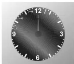
Fig. 3
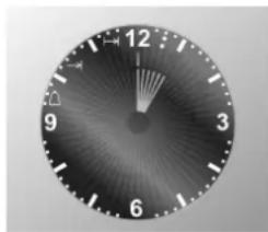
Fig. 4
PROGRAMMING THE COOKING DURATION AND COOKING END

This function is for programming the oven to switch on at a set time and switch off automatically after cooking.
Set the required cooking function and temperature using the control knobs.
In addition to the cooking duration, also set the time the oven is to switch on:
- press the key to enter the programming menu; the display will light up as shown in Fig. 3 and the symbol appears;
- use the + / - keys to set the cooking duration; one press of key + adds one minute cooking time and every twelve minutes one internal segment illuminates (Fig. 4);
- press the key again and use the +/- keys to set the cooking end time (cooking end time minus cooking duration = cooking start time), the symbol →↑appears.
After 7 seconds the display shows the current time while the cooking start time and the cooking duration are shown with the illuminated internal segments, which remain steady until cooking starts and flash for the duration of the cooking time.
At the set time, the oven switches on automatically; at the end of the set cooking time, an audible alarm sounds for 7 minutes; the symbols and the numbers on the dial start to flash, switching the oven off automatically;
- press any key to stop the alarm or the key to delete the programme.
Fig. 5 shows a programming example: the current time is 7:06 and cooking is programmed to start at 8.00 and end at 9.00.
At 8:00, the internal segments between 8 and 9 will start to flash, while the hour hand will remain still.
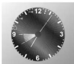
Fig. 5
BEEPER
At the end of each preset function, an audible alarm sounds which turns off automatically after 7 minutes; press the key to turn the beeper off immediately.
Seven different types of audible alarm are available on the appliance; to choose between them press the key for at least 7 seconds; each time the key is pressed again the tone changes.
BRIGHTNESS
The brightness of the clock can be changed; press the and keys simultaneously for at least 5 seconds and then use the f^+ keys to change the brightness of the dial.
GRAPHICS
The graphics of the clock can be changed; press the and keys simultaneously and use the + key to display and choose the preferred graphics.
6. Using the cooking hob
Make sure that the flame caps, the burner caps and the pan supports are fitted correctly.


During normal operations, the appliance heats up considerably. Caution should therefore be used. Do not allow children to approach the appliance. Do not leave the cooking hob unattended while it is on.
6.1 Switching on the burners
All the hob burner knobs have the following symbols:
tap closed
high flame
low flame
The low flame setting is found by turning the knob anticlockwise all the way. All intermediate settings must be selected between the high flame and low flame, never between high flame and closed.
6.1.1 One-touch lighting
The hob burners are equipped with a "one-touch" lighting system. To switch on one of the burners, press the knob corresponding to the required burner and turn it anticlockwise to the low setting. Hold down the knob to activate the automatic "one-touch" lighting system. When the burner is on, hold down the knob for approximately 10 seconds, to allow the safety valve to open. In the event of a power cut, the burner can also be lit with a match (see section "6.1.2 Manual lighting").

Should the burner switch off accidentally, the safety thermocouple blocks the gas flow, even when the tap is open.

The device should not been activated for longer than 15 seconds. If after that time it fails to operate stop pressing the knob, open the window and wait 1 minute before trying again. In case the flame goes out accidentally turn off the knob and do not try to switch on the burner for at least 1 minute.
6.1.2 Manual lighting
To light one of the burners, move a lit match towards the burner, press the corresponding knob and turn it anticlockwise to the minimum setting 山 Release the knob.
6.2 Switching off the burners
At the end of the cooking, return the knob to position
6.3 Abnormal Operation
AUS
Any of the following are considered to be abnormal operation and may require servicing:
- Yellow tipping of the hob burner flame.
- Sooting up of cooking utensils.
- Burners not igniting properly.
- Burners failing to remain alight.
- Burners extinguished by cupboard doors.
Gas valves, which are difficult to turn.
In case the appliance fails to operate correctly, contact the authorised service provider in your area.
7. Using the induction hob
The hob is equipped with one radiant generator per cooking zone. Each generator located below the glass ceramic cooking surface generates an electromagnetic field that induces a thermal current in the base of the pan.
In induction cooking, heat is not transmitted from a heat source, but created by inductive currents directly inside the pan.

Advantages of induction cooking:
- Energy saving thanks to the direct transmission of energy to the pan, compared with traditional electric or gas cooking.
- Safer thanks to the transmission of energy solely to the pan rested on the hob.
Highly efficient energy transmission from the induction cooking zone to the base of the pan.
Rapid heating speed. - Reduced risk of burns, since the cooking surface is heated solely at the base of the pan.
- Spilt food does not stick to the surface of the hob.
7.1 General warnings
Remove all labels and self-adhesives from the ceramic glass.
Before connecting the appliance to the mains, ensure it has been standing at room temperature for at least 2 hours.

People with a pacemaker or other similar devices must ensure that the operation of their devices is not jeopardised by the induction field, the frequency range of which is between 20 and 50kHz .
Do not wear metal objects or necklaces in direct contact with the body. When entering the radiating field of the induction hob, they may overheat with an ensuing risk of scalding. Non-magnetisable metals (e.g. gold or silver) do not carry this risk.
Objects with a magnetic strip (credit cards, swipe cards, floppy discs, etc.) must not be left near the appliance while it is on.
Do not heat canned food or other sealed containers. The pressure that builds up inside the container during cooking may cause it to explode.
Do not place metal objects such as cookware or cutlery on the surface of the hob as they can overheat, with an ensuing risk of scalding.
Never cover the appliance with a cloth or a protection sheet. this is supposed to become very hot and catch fire.
Do not use the glass surface of the hob as a countertop or work surface.
Make sure no cable of any fixed or moving appliance contacts with the glass or the hot saucepan.
Any damage arising from the use of saucepans unsuitable for induction cooking, or of removable accessories between the pan and the radiant element, will void the warranty. The manufacturer cannot be held liable for damage to the hob or related damage arising from improper use.
7.2 Automatic radiant power distribution
The maximum applicable power is distributed among the active radiant elements, the last power level set takes priority over the previous settings on the other radiant elements.
Power is distributed automatically among the three radiant elements on the left (A) and the two on the right (B).
| A B | |||||
| RADIANT ELEMENT | 1∅ 145 | 2∅ 180 | 3∅ 260 | 2∅ 180 | 4∅ 210 |
| POWER (W) | 1400 1600 | 2400 1600 | 2300 | ||
| POWER WITH BOOSTER FUNCTION (W)(ref. section "7.6.3") | 1800 3000 | 3200 3000 | 3200 | ||
| TOTAL MAXIMUM POSSIBLE POWER (W) | 3700 3700 | ||||
| SELECTED POWER LEVEL | 1 2 3 4 5 6 7 8 9 |
| % POWER SUPPLIED | 3 6.5 11 15.5 19 31.5 45 64.5 100 |
When using several radiant elements simultaneously, the last activated element may maintain the set value to the detriment of the other previously set elements, which may then be affected by a reduction in power. On activating the last radiant element, the values on the displays of the previously set elements, will start to flash, automatically showing the new lower power level supplied. If the heating value of any of the radiant elements is manually reduced, the difference in power will be redistributed among the remaining elements.

Given that cooking will continue with new, automatically reset power values, adjustments may need to be made depending on the type of food being cooked.
7.3 Energy regulator table
The table below indicates the power levels that can be set and the type of food that can be cooked at each level. The values may vary depending on the quantity of food and personal taste.
| 1-2 | For heating food, keeping small quantities of water on the boil, making egg- or butter- based sauces. |
| 3-5 | For cooking solid and liquid food, keeping water on the boil, defrosting frozen food, frying 2-3 eggs, cooking fruit and vegetables, general cooking. |
| 6-8 | Cooking meat, fish and vegetable stews, food with more or less water, making jams, etc. |
| 9 | Roasting meat or fish, steak, liver, browning meat or fish, eggs, etc. |
| P | Deep fat frying potatoes etc., bringing water rapidly to the boil. |

7.4 Switching on the induction hob for the first time
Clean the hob with a damp cloth, and then dry the surface thoroughly. Do not use detergent which risks causing blue-tinted colour on the glass surface.
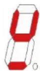
When the hob is first switched on the displays of all the radiant elements light up simultaneously displaying the symbols as shown in the figure; the displays will then switch off immediately without emitting any sound.
If one or more knobs is not in "0" position when the hob is first switched on, the relative displays light up as normal, but the radiant element will not work.
On turning the knob, the relative display will show the adjacent symbol, signalling the radiant element failed to work. The element will only work properly again once the knob is returned to "0" position and a new power value is set.
7.5 Pan recognition
An electronic sensor detects if a pan is present or absent on the radiant element. If the type of pan is unsuitable for magnetic induction cooking (see section "7.5.1") or if the pan is too small (see table "MINIMUM DIAMETER" on p. 94), the adjacent symbol is displayed.
If during cooking a pan is removed from the radiant element without having first returned the relative knob to "0" position, the power value, previously set and shown on the relative display, will be automatically replaced with the symbol .
If the pan is repositioned correctly on the radiant element, the symbol switches off and cooking will resume normally; otherwise, after 10 minutes, the symbol will switch off, the knob will have to be returned to "0" position and a new power value set before the radiant element can be used again.
If a knob is turned to any position before placing a pan on the radiant element, the relative display shows the set power value and then immediately replaces it with the symbol (the radiant element stands by for 10 minutes). If in the meantime a pan is placed correctly on the radiant element, cooking will begin; otherwise the radiant element does not activate and switch off. To reactivate the radiant element, the relative knob must be returned to "0" position and a new power value set.
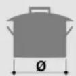
Pan recognition limits: the diameter of the pan base is signalled by a circumference on the cooking zone.
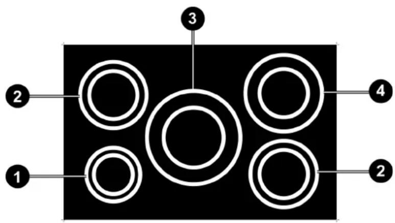

1 0145
2 0180
3 0260
4 0210
MINIMUM DIAMETER (mm)
120 145 180 145

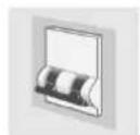
7.5.1 Pans suitable for induction cooking
Manufacturers generally state whether or not their cookware is suitable for induction cooking. The adjacent pictogram indicates the kind of symbol used to denote suitability for induction cooking, usually found on the bottom of the pan.
Only use pans with perfectly flat, smooth bases suitable for induction cooking.
The cookware used for induction cooking must be made of ferrous alloys or ferritic steel, be magnetisable and have a sufficiently thick base.
To check whether the pan is suitable, simply hold a magnet at its base: if it is attracted the pan is suitable for induction cooking. If you do not have a magnet, pour a little water into the pan, rest it on a cooking zone and turn on the hob.
Certain pans can make noise when they are placed on an induction cooking zone. This noise doesn't mean any failure on the appliance and doesn't influence the cooking operating.
SUITABLE COOKWARE UNSUITABLE COOKWARE
Enamelled ferritic steel cookware with thick base.
- Ferrous cast iron cookware with enamelled base.
- Multilayer stainless steel, stainless ferritic steel or aluminium cookware with special base for induction cooking.
Copper, stainless steel, aluminium, fireproof glass, wood, ceramic and terracotta.
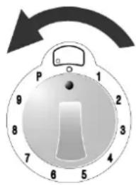
7.6 Switching on a radiant element
Before activating a radiant element, place a suitable pan on the relative cooking circumference.
On turning any knob clockwise, a beep is emitted and all the displays switch on; the one corresponding to the turned knob will show the selected power value, while the others will show the value.
On turning a second knob, no beep is emitted and the display shows the power value set for that knob.
7.6.1 Changing the power level
Each knob has a graduated scale increasing clockwise from level "0" to level "9". The heating power of the radiant elements is increased by turning any knob clockwise from "0" position, and is decreased by turning the knob anticlockwise from the position reached.
The knob's default position corresponds to level "0" (value 0 on the relative display). Turning the knob displays the selected power level on the relative display.
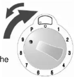
Turning knob clockwise beyond power level "9" will result in a click and an audible signal, which will enable the "Booster" function indicated on the display with the symbol ; then reposition the knob on level "9" (see paragraph "7.6.3").

00
7.6.2 Rapid heating function
This function enables the required power level to be reached more quickly, although it remains active for a very limited period of time.
Starting from "0" position, turn the knob anticlockwise until it clicks and hold it in that position for 2 seconds; the display will light up showing the adjacent symbol. You will then have 10 seconds to turn the knob to the required power level; the display will start flashing alternating symbol with the new power level set with the knob.
The following table gives the rapid heating times to the various power levels.
SELECTED POWER LEVEL
123456789
DURATION IN SECONDS
48 144 230 312 408 120 168 216 -
#
7.6.3 Booster function
Turn the knob clockwise beyond power level "9" until you hear a click and an audible signal (the display shows the adjacent symbol); then reposition the knob on level "9".
The knob must be correctly repositioned on level "9"; otherwise the symbol
P , shown on the display, will be replaced by error code H which signals deactivation of the radiant element; to restore the radiant element, follow the instructions given in paragraph "7.6.7".
The maximum heating time with the Booster function is 10 minutes.
At the end of the maximum heating time, symbol flashes for a few seconds and the power is automatically reset, displaying the value 9.
With the Booster function activated, several consecutive cycles can be repeated.
#
7.6.4 Residual heat
After cooking is finished and the knob is returned to "0" position, the radiant element's display shows the adjacent symbol alternated with the value 0, indicating that that radiant element has just been used and is still hot.
The symbol H will flash for a few seconds, then will become steady and will stay on until the glass temperature has gone below the safety level.
7.6.5 Ventilation
The cooling system is fully automatic. The cooling fan starts with a low speed when the calories brought out by the electronic system reach a certain level. The ventilation starts his high speed when the hob is intensively used. The cooling fan reduces his speed and stops automatically when the electronic circuit is cooled enough.
7.6.6 Overheating
The induction hob is fitted with a safety device that protects the internal electronics against overheating. This device requires no attention from the user and enables the hob to be used confidently without the risk of overheating.

7.6.7 Deactivating a single radiant element
On turning any knob anticlockwise and keeping it in that position for more than 30 seconds, the relative display will show the adjacent symbol to indicate the radiant element is deactivated.

If the knob is not positioned correctly, the relative display will show error code which signals deactivation of the radiant element. It is not necessary to call Customer Service; to restore the radiant element, simply return the knob to position "0" and reset the required power value.

This function is advisable to disable a single radiant element if it is faulty or malfunctioning.
After the radiant element has been repaired by the authorised Technical Support Service, it can be reactivated by turning the knob anticlockwise again and keeping it in that position for more than 30 seconds.
7.7 Automatic switch-off
An automatic counter counts the time elapsing since the last power variation. This determines the maximum heating duration, which varies according to the power level selected.
If a radiant element is left on by mistake (with a correctly positioned pan), it will switch off automatically once the maximum heating duration for the selected power is reached.
| SELECTED POWER LEVEL | 1 | 2 | 3 | 4 | 5 | 6 | 7 | 8 | 9 | P |
| MAX TIME IN MINUTES | 360 | 360 | 300 | 300 | 240 | 90 | 90 | 90 | 90 | 10 |
7.8 Switching off manually
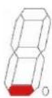
Turn all the knobs to "0" position. Each display will show a flashing dot as in the adjacent figure; after 15 seconds all the displays will switch off, a beep will be emitted and the appliance with go to stand-by.

7.9 Child safety
The radiant elements can be deactivated. Turn the first two knobs on the left anticlockwise simultaneously and keep them in this position for least 2 seconds, until all the displays show symbol .
After a few minutes the symbols switch off, but the radiant elements will not activate and the above-mentioned lock symbols appear on all displays if any knob is turned.
The deactivation has no time limit. A prolonged power failure may cancel this deactivation.
To reactivate the radiant elements, turn the first two knobs on the left anticlockwise simultaneously.
7.10 In the event of faults and failures

If a defect is noticed, switch off the appliance and turn off the electrical supplying.
Do not attempt to use a faulty radiant element until it is repaired by the authorised Technical Support Service.
Any repairs must be carried out exclusively by qualified personnel. Do not open the appliance for any reason.
If the glass surface is damaged, switch off the appliance immediately to prevent the risk of electric shocks and contact the Technical Support Service.
If a radiant element is faulty, the remaining elements can still be used normally.
To clear the error code from the displays, set all the knobs to "0" position and set new power values.
The following list includes the most frequent failures, the causes of which can be removed by the user or via the Technical Support Service.
| FAULT CAUSE REMEDY | ||
| The hob or the cooking zones do not switch on. | The appliance is not correctly connected to the mains. | Reconnect the appliance to the mains. |
| The hob lock function has been activated. | Deactivate the lock by following the instructions in section 7.9 | |
| U | The display shows the adjacent symbol. | There is no pan on the cooking zone. |
| The pan is not suitable for magnetic induction cooking. | ||
| The diameter of the base of the pan is too small for the cooking zone. | ||
| F | The display shows the adjacent symbol. | The knob is not positioned correctly. |
| E | The display shows the adjacent code alternated with numbers or letters. | |
| The hob or a cooking zone switches off. | The safety device has triggered. The device triggers when a cooking zone is left on by mistake. | Return the relative knob to "0" position. |
| An empty pan has overheated. | Remove the empty pan from the cooking zone. | |
| The cooling fan stays on after the hob is switched off. | This is not a fault. The fan stays on until the hob has cooled down. The fan will switch off automatically. | |
8. Using the ovens
8.1 General warnings

When the oven or grill is operating, the outer walls and oven door can become very hot.
Keep children away from the appliance.
Do not allow children to sit on the oven door or play with it.
Do not use the door as a stool.
Never stand aluminium pots or foil on the base of the oven, as this may seriously damage the oven enamel.
Do not cook food on the bottom of the oven.
When using the oven for the first time, or after a power cut, the display flashes regularly indicating 0:00. To set the display, refer to section "SETTING THE TIME" on page 83.
Do not attempt to disassemble the oven door without consulting the relative instructions carefully (refer to section "11.1 Removing the oven door"): the hinges on the oven door may injure the hands.

If during normal operation the oven interrupts heating and the programmer display begins to flash and goes to zero, check whether:
there has been a current interruption.
If the block occurs again after the cooking programme has been restarted, this means that the safety device has been tripped. This device intervenes in the event of a thermostat fault and prevents oven overheating. In such case, we recommend that you not try to light the oven again and that you contact your nearest service centre.
8.2 Storage drawer (only available on certain models)
The cookers are fitted with a storage drawer below the oven. Only store the cooker's metallic accessories in the storage drawer.

The drawer becomes hot while the oven is in use; avoid contact with the internal parts to prevent scalding.
Do not store inflammable material such as cloths, paper or similar in the storage drawer.
8.3 Risk of condensation

- Some cooking with high water content combined with the use of certain functions can cause the formation of condensation on the door's inner glass. To prevent this occurring, open the oven door for a few seconds once or twice while cooking.
- Do not leave food to cool in the oven after cooking to prevent condensation forming on the door's inner glass, which may drip out of the oven when the door is opened.
8.4 Using the electric multifunction oven

The end of cooking display and the control knobs on the main oven have no bearing on the operation of the auxiliary oven.
8.4.1 Switching on the oven for the first time
The first time it is used, the oven may smoke or give off an acrid smell caused by oily residue from manufacturing that may give unpleasant odours or flavours to food. Before putting food in the oven, heat to the maximum temperature for 30-40 minutes with the door closed and wait until the smoke or odour has stopped.

To prevent any steam in the oven from scalding, proceed as follows: turn the function switch knob to ,r to function ; open the door in two stages: hold it partly open (approx. 5 cm) for 4-5 second then open it completely.
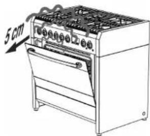
Should you need to adjust the food, leave the door open for as short a time as possible to prevent the temperature inside the oven from lowering to such an extent as to jeopardise cooking.
8.4.2 Traditional cooking
Turn the function switch knob to position and the thermostat knob in correspondence with the required temperature value. For differentiated heating over or below the food, set the function selector switch to position (hot above) or (hot below). For more uniform heating throughout the oven, turn the function switch knob to position

The oven is equipped with an automatic cooling system regulated by the temperature of the door. When the limit temperature is reached, the cooling fan automatically activates and then deactivates when the temperature of the door goes below the preset limit. The cooling fan may stay on after the oven has turned off.
In case that does not happen, switch off the appliance and contact the Technical Service immediately.
8.4.3 Convection cooking
Turn the function switch knob to position; turn the thermostat knob in correspondence with the required temperature value.
8.4.4 Cooking with the ventilated grill (with closed door)
Turn the function switch knob to position; turn the thermostat knob in correspondence with the maximum temperature value.
8.4.5 Cooking with the grill + roasting spit (with closed door)
Turn the function switch knob to position turn the thermostat knob in correspondence with the maximum temperature value. The grill and spit operate at the same time, allowing for cooking on the spit.
8.4.6 Cooking with the roasting spit (with closed door)
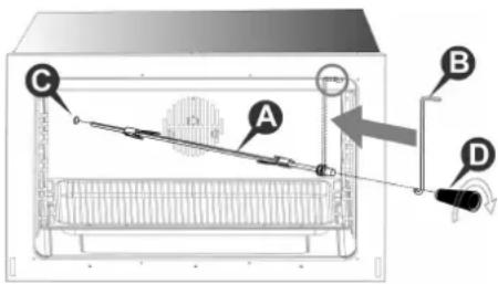
If your oven model has a roasting spit, proceed as follows:
- Slide the meat to be cooked on the spit rod A and secure it with the adjustable forks.
- Hang the hook B at the top of the oven as shown in the figure.
- Place the spit rod A into the hole C in the oven casing; before closing the oven door, make sure that the rod A is correctly inserted into the hole C (insert the rod and turn it slightly back and forth).
- Hang the other end of the spit rod to the hook B (the pulley of the rod A is situated on the handle of the hook B).
- Close the oven door and activate the spit by turning the function selector knob to the position.
- When cooking is completed, open the oven door and remove the spit rod using the plastic handle D, which is screwed into the base of the rod A.
8.4.7 Defrosting
Turn the function switch knob to position the thermostat knob to position : in this way the motor fan is activated, which moves the air inside the oven and encourages frozen food to defrost.
8.4.8 Switching off the oven
The oven is switched off by returning the thermostat knob to position
8.5 Using the auxiliary oven with natural convection

The end of cooking display and the control knobs on the main oven have no bearing on the operation of the auxiliary oven.
The auxiliary oven with natural convection is equipped with:
- a heating element positioned on the base of the oven (at the bottom);
- a heating element positioned on the ceiling of the oven (at the top) + grill.
8.5.1 Switching on the auxiliary oven for the first time
The first time it is used, the auxiliary oven may smoke or give off an acrid smell caused by oily residue from manufacturing that may give unpleasant odours or flavours to food. Before putting food in the oven, heat the auxiliary oven to the maximum temperature for 30-40 minutes with the door closed and wait until the smoke or odour has stopped.
To start heating the auxiliary oven, select the temperature (100÷ 260) or the required function by turning the thermostat knob.
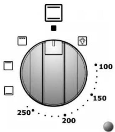
8.5.2 Cooking with the grill (with closed door)
Turn the thermostat knob to position and let the auxiliary oven preheat for approximately 5 minutes. For correct operations, position the grill shelf on the third guide from the bottom. It is however possible to vary the position of the grill shelf according to personal taste and different cooking requirements. Before putting food in the oven, allow it to preheat for 5 minutes. A cooling system prevents the control knobs from overheating.
8.5.3 Cooking with the spit (with closed door)
If your oven model has a roasting spit, proceed as follows:
- turn the thermostat knob to position and let the auxiliary oven preheat for approximately 5 minutes;
- insert the food on to the spit rod A taking care to hold it firm with the two forks B, and balancing it so as to avoid straining the gearmotor;
- place the pulley C of the spit rod onto the support D after introducing the opposite end into the hole E, until the coupling with the gearmotor F so that the rod rotates;
- pour a little water into the dripping pan and position it under the spit rod;
- monitor the cooking from time to time and check the spit rod is rotating correctly;
- at the end of the cooking, switch off the auxiliary oven by returning the thermostat knob to position
- remove the spit rod from the auxiliary oven using the knob G and wearing an oven glove.
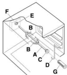
8.5.4 Switching off the auxiliary oven
The oven is switched off by returning the thermostat knob to position
9. Cooking suggestions
9.1 Suggestions for using the hob burners correctly
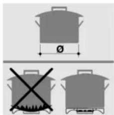
The diameter of the base of cooking recipients should fit the diameter of the burner used (see adjacent table). The burner flame must never be wider than the diameter of the recipient. Use recipients with a flat base. Where possible use pots with a lid, as this allows less power to be used. To reduce cooking times for vegetables, potatoes, etc., use little water.
| Burner | Recipient diameter (in cm) |
| Rapid | from 24 to 26 |
| Semi rapid | from 16 to 22 |
| Auxiliary | from 8 to 14 |
| Triple-ring | from 24 to 26 |
9.2 Suggestions for using the induction hob correctly
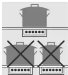
For best cooking results and energy saving, only use cookware suitable for induction cooking. The diameter of the base of the cookware must be the same as the diameter of the circle on the cooking zone (section "7.5"); if they do not match energy will be wasted.
The base of the cookware must be ferrous alloy or ferritic steel and perfectly flat. It must also be perfectly clean and dry, as must the glass in the cooking zone.
Do not use pans with a rough, scratched or damaged base, as they may scratch the hob surface.

Sugar, synthetic materials or aluminium sheets must not contact with the heating zones. These may cause breaks or other alterations of the glass ceramic surface by cooling. Before cooking sugary foods, it is advisable to treat the glass ceramic surface with a specific silicone-based product to protect the hob surface from any burned-on food residue.
Do not put or leave empty saucepans on the vitroceramic hob.
Avoid dropping objects, even little ones, on the vitroceramic hob.
Sand or other abrasive materials may damage the ceramic glass.
The glass may be scratched if pans are placed on top of abrasive residue. Scratches do not, however, affect the operation of induction cooking.
Make sure the appliance fan is working correctly.
9.3 Suggestions for using the oven correctly

The oven allows to optimise cooking. It is possible to cook traditionally, with convection and with the grill.
The oven door should be completely closed for all types of cooking.

9.3.1 Traditional cooking
With this type of cooking, the heat comes from the top and the bottom. It is therefore preferable to use the central guides. If the cooking requires a hotter temperature from the bottom or from the top, use the lower or upper guides. Traditional cooking is recommended for all food that requires high cooking temperatures, or long brazing times. This system is also recommended when cooking with recipients made of terracotta, porcelain and similar materials.

9.3.2 Convection cooking
With this type of cooking, the food is heated by preheated air that is circulated in the oven thanks to a fan located on the rear wall of the oven. Heat rapidly and evenly reaches all parts of the oven, thus enabling different food to be cooked at the same time on different shelves. Humidity is eliminated from the air and the drier area prevents odours and flavours from being spread and mixed.
The possibility of cooking on more than one shelf allows you to cook many different dishes at the same time. Biscuits and mini pizzas can be cooked in three different baking tins. The oven, however, can also be used for cooking on a single shelf. The lower shelves can be used so that it is easier to monitor cooking.
Convection cooking is particularly convenient for bringing frozen food rapidly back to room temperature, for sterilising preserves or home-made fruit in syrup and, finally, for drying mushrooms or fruit.

9.3.3 Cooking with the grill
The heat comes from the top. Almost all meat can be grilled, with the exception of lean game and dishes such as meat-loaf. Meat and fish to be grilled should be lightly drizzled with oil and placed on the grid bars, which should be placed in the guides closest to or farthest away from the grill element, depending on the thickness of the meat, so as to avoid burning the surface and cooking too little inside.
Suitable for: relatively thin meat; toasted sandwiches.

Position the grill pan on the lowest level to collect the juices and fat; pour one glass of water into the grill pan to prevent smoke forming due to fat overheating.

9.3.4 Cooking with the ventilated grill
Using the combination of grill and fan.
This type of cooking allows the heat to penetrate gradually inside the food, even though the surface is directly exposed to the grill.
Suitable for: thicker meat; game-birds.
9.3.5 Cooking meat and fish
Meat to be cooked in the oven should weigh at least 1kg . Very tender red meat to be cooked rare (roast beef, fillet, etc.), or which should be well cooked on the outside and preserve all its juices on the inside, require cooking on high temperatures for a short time (200 - 250^) . White meat, gamebirds and fish require cooking on low temperatures (150 - 175^) .
The ingredients for the sauce should only be placed in the baking tin if the cooking time is short, otherwise, they should be added in the last half hour. Meat can be placed on an ovenproof plate or directly on the grid bars, below which the dripping pan should be placed to collect the juice. Press the meat with a spoon to check if it is done. If it is firm, it is cooked.
At the end of the cooking, wait at least 15 minutes before cutting the meat so as not to lose the juices. Before serving, plates can be warmed in the oven at minimum temperature.
9.3.6 Baking
Beaten mixtures must stick to the spoon because excess fluidity would prolong the cooking time.
Sweets require moderate temperatures (generally between 150 - 200^ ) and require preheating (approximately 10 minutes). The oven door must not be opened until at least 34 of the way through the cooking time.
9.3.7 Recommended cooking tables
Cooking times vary according to the nature, homogeneity and volume of the food. We recommend monitoring your first attempts and checking the results, as similar results are obtained by cooking the same dishes in the same conditions. The following three tables (I, II and III) provide guidelines.
TABLE OF CONVECTION AND TRADITIONAL COOKING TIMES (I)
| TYPE OF COOKING | QUANTITY KG. | POSITION OF GUIDE FROM BOTTOM | TEMPERATURE °C | TIME IN MINUTES | ||
| CONVECTION | TRADITIONAL | CONVECTION | TRADITIONAL | |||
| BAKING | ||||||
| WITH BEATEN MIXTURE, IN A TIN | 1 | 1-3 | 2 | 175 | 200 | 60 |
| WITH BEATEN MIXTURE, ON THE DRIPPING PAN | 1 | 1-3 | 2 | 175 | 200 | 50 |
| SHORT PASTRY, PIE BASE | 0.5 | 1-3 | 3 | 175 | 200 | 30 |
| SHORT PASTRY WITH MOIST FILLING | 1.5 | 1-3 | 2 | 175 | 200 | 70 |
| SHORT PASTRY WITH DRY FILLING | 1 | 1-3 | 2 | 175 | 200 | 45 |
| MIXTURE WITH NATURAL LEAVENING | 1 | 1-3 | 1 | 175 | 200 | 50 |
| SMALL CAKES | 0.5 | 1-3 | 3 | 160 | 175 | 30 |
| MEAT | ||||||
| VEAL | 1 | 2 | 2 | 180 | 200 | 60 |
| BEEF | 1 | 2 | 2 | 180 | 200 | 70 |
| ENGLISH STYLE ROAST BEEF | 1 | 2 | 2 | 220 | 220 | 50 |
| PORK | 1 | 2 | 2 | 180 | 200 | 70 |
| CHICKEN | 1-1.5 | 2 | 2 | 200 | 200 | 70 |
| STEWS | ||||||
| BEEF STEW | 1 | 1 | 2 | 175 | 200 | 120 |
| VEAL STEW | 1 | 1 | 2 | 175 | 200 | 110 |
| FISH | ||||||
| FILLET, STEAK, COD, HAKE, SOLE | 1 | 1-3 | 2 | 180 | 180 | 30 |
| MACKEREL, TURBOT, SALMON | 1 | 1-3 | 2 | 180 | 180 | 45 |
| OYSTERS | 1 | 1-3 | 2 | 180 | 180 | 20 |
| TIMBALE | ||||||
| PASTA TIMBALE | 2 | 1-3 | 2 | 185 | 200 | 60 |
| VEGETABLE TIMBALE | 2 | 1-3 | 2 | 185 | 200 | 50 |
| SWEET AND SAVOURY SOUFFLÉS | 0.75 | 1-3 | 2 | 180 | 200 | 50 |
| PIZZA AND CALZONE | 0.5 | 1-3 | 2 | 200 | 220 | 30 |
The times refer to cooking on one shelf only; for more than one shelf increase the time by 5-10'.
The cooking times do not include preheating which takes approximately 15^
- When cooking on more than one shelf, the guides are given in the preferential position.
For beef, veal, pork and turkey roasts, either with bone or rolled, increase the time by 20'.
TABLE OF COOKING TIMES WITH GRILL AND VENTILATED GRILL (II)
| TRADITIONAL GRILLING | ||||
| TYPE OF COOKING QUANTITY | KG. | POSITION OF GUIDE FROM BOTTOM | TEMPERATURE °C | TIME IN MINUTES |
| CHICKEN | 1-1.5 | 3 | MAX | 30 PER SIDE |
| TOASTED SANDWICHES | 0.5 | 4 | MAX | 5 PER SIDE |
| SAUSAGES | 0.5 | 4 | MAX | 10 PER SIDE |
| PORK CHOPS | 0.5 | 4 | MAX | 8 PER SIDE |
| FISH | 0.5 | 4 | MAX | 8 PER SIDE |
| GRILLING WITH VENTILATED GRILL | ||||
| TYPE OF COOKING QUANTITY | KG. | POSITION OF GUIDE FROM BOTTOM | TEMPERATURE °C | TIME IN MINUTES |
| ROAST PORK | 1.5 | 2 | 170 | 180 |
| ROAST BEEF | 1.5 | 3 | 220 | 60 |
| CHICKEN | 1.2 | 2 | 190 | 90 |
The dripping pan for collecting cooking juices should always be positioned in the 1^st guide from the bottom.
TABLE OF DEFROSTING TIMES (III)
| DEFROSTING | |||
| TYPE OF FOOD QUANTITY | KG. | POSITION OF GUIDE FROM BOTTOM | TIME IN MINUTES |
| READY-TO-EAT DISHES | 1 | 2 | 45 |
| MEAT | 0.5 | 2 | 50 |
| MEAT | 0.75 | 2 | 70 |
| MEAT | 1 | 2 | 110 |
- Defrosting at room temperature has the advantage of not modifying the flavour and appearance of food.
10. Cleaning and maintenance
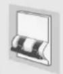
Before cleaning or carrying out maintenance, switch off the power supply to the appliance and close the gas tap.

Warning: Servicing should be carried out only by authorised personnel.
Do not clean the surfaces of the appliance when they are still hot.
Use only suitable detergents to clean the surfaces of the appliance. The manufacturer declines all responsibility and is not liable for damage arising from the use of unsuitable and/or other detergents than those indicated.
Do not use pressure or steam spray guns to clean the appliance.
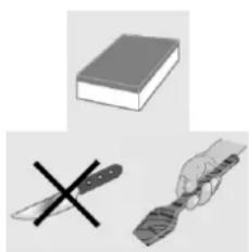
10.1 Cleaning the stainless steel surfaces
To clean and preserve the stainless steel surfaces, use a solution of warm water and vinegar or neutral soap. Pour the solution onto a damp cloth and wipe the steel surface, in the direction of the satin finish, rinse thoroughly and dry with a soft cloth or chamois leather.
Do not under any circumstances use metallic sponges or sharp scrapers that may damage the surfaces. Only use non-scratch, non-abrasive sponges and, if necessary, wooden or plastic utensils.
10.2 Cleaning the enamelled surfaces
Clean with a non-scratch, non-abrasive sponge dampened with neutral soap and water. Grease stains can easily be eliminated with hot water or a product specifically made for cleaning enamel. Rinse carefully and dry with a soft cloth or a piece of deerskin.
Do not use products containing abrasives, scouring pads, steel wool or acid, which may spoil the surfaces. Do not leave acid or alkaline substances on the enamel (lemon juice, vinegar, salt, etc.).
10.3 Cleaning the polished surfaces
Clean with a non-abrasive, scratchproof sponge dampened with warm water and neutral soap or with a standard detergent for polished surfaces. Rinse and dry carefully with a soft cloth. Abrasive pastes, coarse wire pads, steel wool or acid will damage the surfaces. Do not use alcohol.
10.4 Cleaning the wooden surfaces, accessories and parts
We recommend using cleaning products normally available on the market. These products ensure the wood is preserved over time. If these products are not available, we recommend removing the dirt as soon as possible using a cloth dampened with water and neutral soap. Rinse thoroughly and dry with a soft cloth. Remove the larger incrustations and more stubborn residues using a scratch-resistant scraper for wood or a special sponge designed for delicate surfaces.
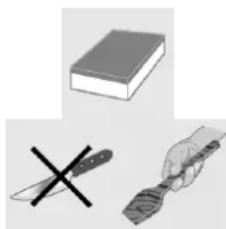
Do not under any circumstances use metallic sponges or sharp scrapers that may damage the surfaces.
Do not wash wooden accessories and parts in the dishwasher. Keep dry and avoid extreme temperature changes. Excessive humidity and extreme temperature changes may irrevocably deform the wooden accessories and parts.
10.5 Cleaning the knobs and the control panel
Clean the knobs and the control panel with a damp cloth.
10.6 Cleaning the grids and burners
To clean the grids and hob burners, remove them from their housing by lifting them upwards as shown in the figure, and immerse them in a solution of warm water and non-abrasive neutral detergent for about ten minutes. Rinse and dry carefully.
Do not wash the burners or the plates in the dishwasher.
Always check that none of the burner openings is clogged.
Be sure to refit the burner correctly, checking the flame is uniform.
We recommend carrying out this operation at least once a week and each time it is necessary.
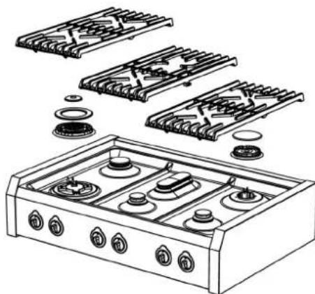
10.7 Cleaning the igniter plugs and thermocouples
In order for the igniter plugs and thermocouples to operate correctly, they must be kept clean at all times. Check them frequently and, if necessary, clean them with a damp cloth. Dry thoroughly.
Any dry residue should be removed with a toothpick or needle, taking care not to damage the insulating ceramic part.
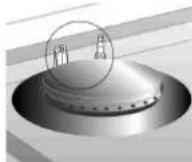
10.8 Cleaning the induction hob
The induction hob requires no special maintenance or cleaning. If burned-on food residues remain near the cooking zone after cooking, remove them using a scratch-resistant scraper, rinse with water and dry well with a dry cloth. Regular use of the scraper avoids the use of chemical cleaning products.
Before moving or sliding pans onto the hob, ensure that there are no crumbs or impurities that may cause scratches.
Do not use abrasive sponges or detergents. Avoid using aggressive chemical products, such as oven cleaning sprays, stain-proof products or other products such as bathroom or all-purpose cleaners.

Take care that the hot glass ceramic hob does not come into contact with plastic, aluminium foil, sugar or food containing sugar. These substances can damage the surface of the hob and should be removed immediately using a scratch-resistant scraper.
Before cooking sugary foods, it is advisable to treat the glass ceramic surface with a specific silicone-based product to protect the hob surface from any burned-on food residue.
To clean the surface of the glass ceramic hob, proceed as follows:
- Remove the larger incrustations and more stubborn residues using a scratch-resistant scraper or a special sponge designed for delicate surfaces.
- Wait for the hob surface to cool down completely, pour a few drops of detergent and rub with kitchen roll or a clean cloth. Alternatively, use a special sponge designed for delicate surfaces.
- Wipe over the hob surface with a damp cloth, or with the dry side of a special sponge.

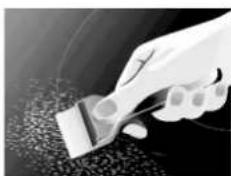
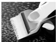
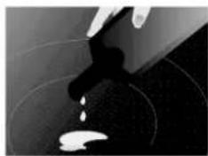
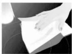

10.9 Cleaning the oven
In order to preserve the oven well, it should be cleaned regularly, each time it is used if possible, after leaving it to cool: in this way it is possible to remove any residue more easily, preventing it from burning the next time the oven is used.
Clean the stainless steel parts and enamelled parts as described in the corresponding sections "10.1 Cleaning the stainless steel surfaces" and "10.2 Cleaning the enamelled surfaces".
Take out all the removable parts and wash them separately. Rinse and dry thoroughly with a clean cloth.
10.9.1 Cleaning the oven walls
Never use detergent products to clean this type of oven.
The walls of the oven can be cleaned using white vinegar and wiped with a cloth dampened with water. Subsequently, heat the oven for at least one hour at 150^ to facilitate cleaning. When the oven has cooled, wipe it again with a damp cloth.
10.9.2 Cleaning the oven door
We recommend always keeping the oven door clean. Use kitchen roll and on tougher dirt use a damp cloth and household detergent.
Spray products for cleaning the oven must not be used to clean the fan and the thermostat sensor inside the oven compartment.
11. Special maintenance
Periodically, it is necessary to maintain or replace some parts that are subject to wear and tear. Specific instructions are given below for each type of maintenance.
Before carrying out maintenance, switch off the power supply to the appliance and close the gas tap.
11.1 Removing the oven door
The oven door can be completely removed to enable more thorough cleaning.
Though this operation is possible, it should not be performed by everyone, as it requires the strength to hold up the door and a minimum of expertise to re-fit it. If you are not sure of being able to do this, we recommend that you clean the door without taking it off or, in special cases, that you contact the nearest authorised service centre.
To remove the door, proceed as follows:
open the oven door and release the safety catches of the hinges by turning the respective pins A (one for each hinge) backward;
- partially close the door until there is no more load tension on the springs (the door will form an angle of about 30^ );
using both hands, accompany the movement of the door towards closure and simultaneously lift it upward;
- turn the lower part of the door towards the outside to free the hinges B from their seats.
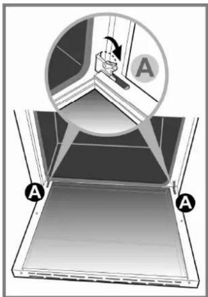
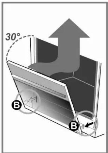
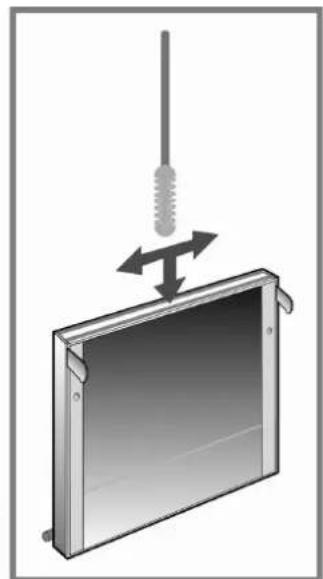
The inner glass can be removed for more thorough cleaning.
Proceed as follows:
- loosen screw C by half a turn to enable the catch to be lifted from right to left;
- lift the two catches and slide out the inner glass;
to refit the glass, follow the above instructions in reverse order.
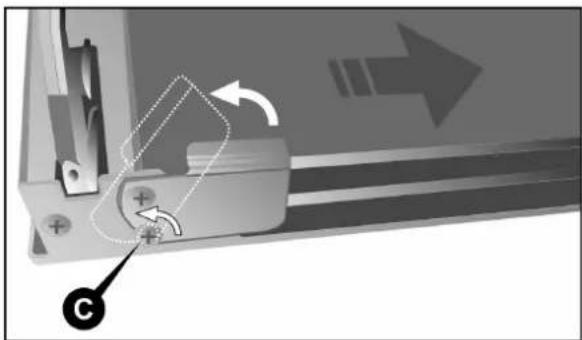
To clean the area between the outer glass and the intermediate glass, use a soft brush in the space between the glass panels, as shown on p. 109.
To refit the door, follow the instructions on p. 109 in reverse order.
When the hinges B are back in their seats, open the door all the way and re-fit the safety catches of the hinges, lowering the respective pins A (one for each hinge).

CAUTION: After re-fitting the door, always be sure to re-fit the hinge safety catches.
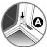
11.2 Removing the side rack-holder frames
The rack-holder frames can be removed to clean them separately and to facilitate cleaning the oven walls. The frames are hooked to the oven wall in the three points indicated by the arrows in the figure (detail 1).
- Press downward with your fingers as shown in detail 2 of the figure to release the frame from the upper pin.
- Lift the frame upward and take it out.
To re-fit proceed in the inverse direction. Set the lower part of the frame on the respective pins and press the upper part against the oven wall until it hooks onto the pin.
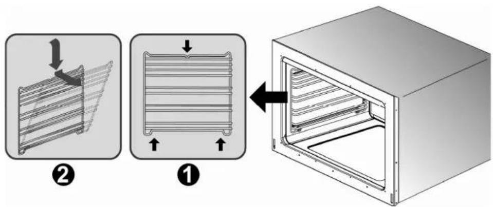
11.3 Removing and cleaning the inside oven fan
The inside fan of the ventilated oven may require periodic cleaning. To disassemble the fan proceed as follows:
- Make sure that the power supply to the appliance is switched off.
- Remove all inside components (dripping pan, shelves).
- Loosen and remove the four screws A from the cover panel.
- Remove the cover panel B.
- Use a coin to loosen the fixing nut C of the fan (this threading is inverse; to loosen turn clockwise).
- Remove the fan D and wash it by immersing it in warm water and dish detergent. Never use abrasive or corrosive detergents, powdered products, or metal scrubbers. Rinse the fan and dry it thoroughly.
Re-fit the fan and the cover by working in the inverse direction to the instructions for removal.
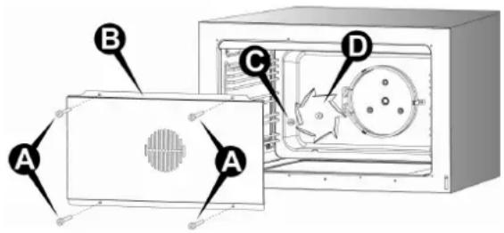
11.4 Replacing the oven light bulb

Before carrying out maintenance, switch off the power supply to the appliance.
Proceed as follows:
open the oven door;
- unscrew the glass safety cap anticlockwise;
- unscrew the bulb and replace it with another one for high temperatures (300^) with the following characteristics:
Voltage: 230 V / 50 Hz
Voltage: 230 V1N~/50 Hz
Power: 15 W
Attachment: E 14
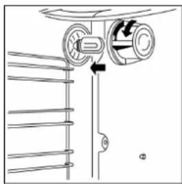
AUS
- Refit the glass cap and switch on the power. It is possible to check that the oven light is working even when the door is closed by turning the function switch knob to position
SCHEMA “A” SCHEMA “B” SCHEMA “C”
| AT | ● | ISO 228-1 |
| BE | ● | |
| CH | ● | |
| DE | ● | |
| DK | ● | |
| ES | ● | ● |
| FI | ● | ● |
| FR | ● | |
| GB | ● | |
| IE | ● | |
| IT | ● | ● |
| NL | ● | |
| NO | ● | ● |
| PT | ● | ● |
| SE | ● | ● |
1.1 Assistance technique 169
1.1 Assistance technique
SCHEMA “A” SCHEMA “B” SCHEMA “C”
BRANCHEMENT D'ORIGINE CONFIGURE PAR LE FABRICANT.
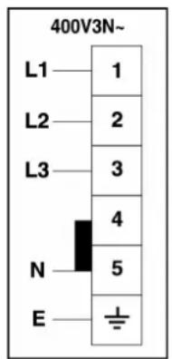
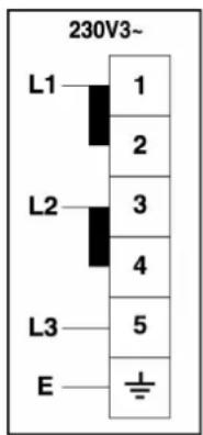
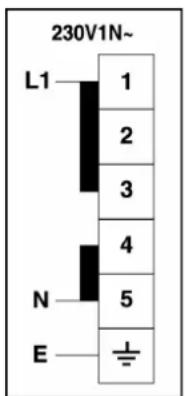
BRANCHEMENT A LA BOITE À BORNES
| ISO 7-1 | ||
| AT | ● | |
| BE | ● | |
| CH | ● | |
| DE | ● | |
| DK | ● | |
| ES | ● | ● |
| FI | ● | ● |
| FR | ● | |
| GB | ● | |
| IE | ● | |
| IT | ● | ● |
| NL | ● | |
| NO | ● | ● |
| PT | ● | ● |
| SE | ● | ● |
| AT | ● | |
| BE | ● | |
RECIPIENTS APPROPRIES RECIPIENTS NON APPROPRIES
8.4.3 Cuisson a convection
www.steel-cucine.com
STEEL SRL
Via dell'Agricoltura 21
41012 Carpi (MO) - Italy
T. +39 059 645180
F. +39 059 6220804
P. Iva 02593690361