CBT63241N - Basket CANDY - Free user manual and instructions
Find the device manual for free CBT63241N CANDY in PDF.

| Brand | Candy |
| Model | CBT63241N |
| Product type | Kitchen hood |
| Power supply | 220-240 V ~ 50 Hz |
| Insulation class | Class I |
| Recommended fuse | MAX 6 A |
| Minimum distance (electric hob) | 650 mm |
| Minimum distance (gas or other fuel hob) | 750 mm |
| Recommended exhaust duct diameter | 150 mm (min. 120 mm) |
| Number of speeds | 3 (depending on model: rocker switch, touch) |
| Lighting | LED or halogen bulbs (depending on version) |
| Grease filter | Washable aluminum filter (dishwasher or manual) |
| Charcoal filter (optional) | AF 90 or AF 100 – replace every 3-5 months |
| Functions | Exhaust or recirculation mode, 15 min timer, filter cleaning indicator |
| Cleaning metal filters | Every 2-3 weeks or when "C" signal appears |
| Replacing bulbs | LED 1 W or halogen – disconnect before intervention |
| Installation | Wall or under-cabinet mounting, with exhaust duct |
| Safety | Automatic shut-off, backdraft protection, use with combustion appliances |
| Technical service | Contact an authorized service, warranty conditions apply |
Frequently Asked Questions - CBT63241N CANDY
User questions about CBT63241N CANDY
0 question about this device. Answer the ones you know or ask your own.
Ask a new question about this device
Download the instructions for your Basket in PDF format for free! Find your manual CBT63241N - CANDY and take your electronic device back in hand. On this page are published all the documents necessary for the use of your device. CBT63241N by CANDY.
USER MANUAL CBT63241N CANDY
CBT9240/2X - CBT6324/1X - CBT6324/1W - CBT6324/1N
CBT6130/2X - CBT6240/1LN - CBT6240/1LW - CBT6240/1LX
natural_image
3D rendering of a stainless steel kitchen ventilation duct with ventilation grilles and ventilation grilles (no text or symbols visible)1 TECHNICAL DRAWING 3
2 WARNINGS AND SAFETY PRECAUTIONS....4
2.1 Life-Threatening Danger, Poisoning Danger 6
2.2 Danger of electric shock! 6
2.3 Danger of physical injury!......6
2.4 Danger of burn, danger of electric shock! 7
2.5 Dangers of fire and physical injury!....7
3 USAGES WITH AND WITHOUT CARBON USE 8
3.1 Replacement of Carbon Filter 9
3.2 Replacement of AF 90 Carbon Filter 9
3.3 Replacement of AF 100 Carbon Filter 9
4 CLEANING AND PREVENTIVE MAINTENANCE 10
4.1 Washing in Dishwasher 10
4.2 Hand Wash 10
4.3 Removal/Installation of Aluminium Filter 10
5 INSTALLATION OF APPLIANCE 11
5.1 Installation and Unpacking of the Appliance....11
5.2 Installation and Unpacking of the Appliance 11
5.3 Exhaust Air Mode....12
5.4 Air Discharge Line....12
5.5 Checking the Wall 12
5.6 Electrical Connection 12
5.7 Danger of Electric Shock! 12
6 OVERVIEW OF APPLIANCE 13
7 ASSEMBLY OF PRODUCT 14
8 USE OF PRODUCT 15
9 REPLACEMENT OF LAMPS....17
9.1 Replacement of Halogen Lamp 17
9.2 Replacement of Spark Plug Lamp 17
9.3 1W Replacement of LED Lamp ....17
10 AUTHORIZED TECHNICAL SERVICE....18
10.1 Potential Failures and Solutions .... 19
10.2 Technical Table....19
"Complies with EEE Regulation. No PCB* Included"
* PCB = Printed Circuit Board
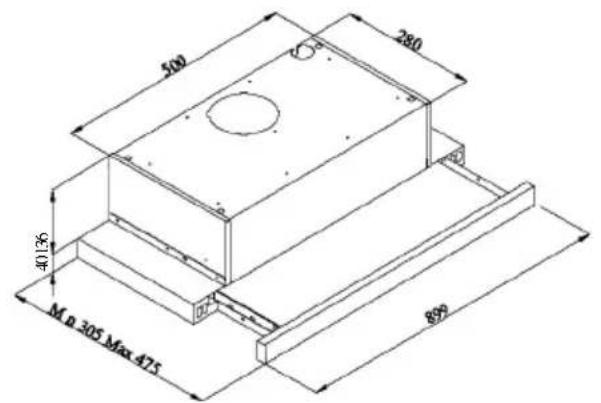
1 TECHNICAL DRAWING
text_image
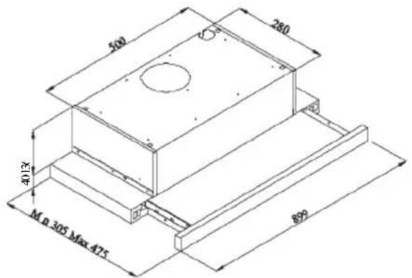
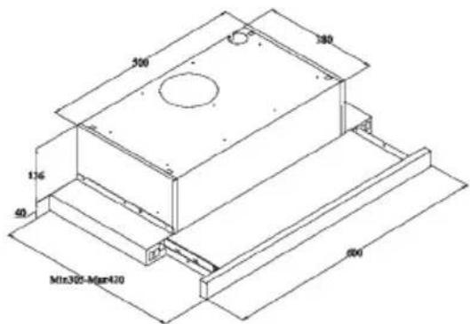
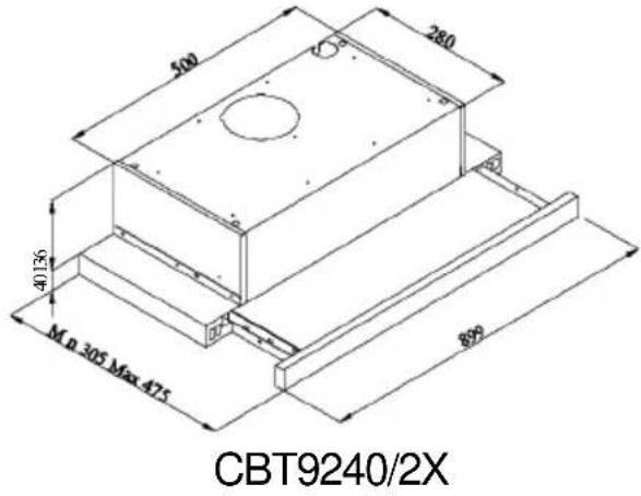
500 280 40136 M n 305 Max 475 890CBT9240/2X
text_image
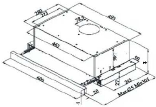
280 223 493 28.27 462 16 50 600 20 27 243 Max Q5 Min 105CBT6324/1X
CBT6324/1W
CBT6324/1N

text_image
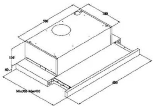
300 140 116 40 Min300-Mgn420 600CBT6130/2X
CBT6240/1LN
CBT6240/1LW
CBT6240/1LX
Fig. 1: TECHNICAL DRAWING
2 WARNINGS AND SAFETY PRECAUTIONS
■ This appliance can be used by children aged from 8 years and above and persons with reduced physical, sensory or mental capabilities or lack of experience and knowledge if they have been given supervision or instruction concerning use of the appliance in a safe way and understand the hazards involved.
■ This product is designed for home use.
■ Usage voltage of your product is 220-240 Volt\~50 Hz.
■ Power cord of your product is fitted with a grounded plug. This cord must be plugged into a grounded outlet.
■ The whole electrical wiring must be installed by a qualified electrician.
■ Installation by unauthorized persons could lead to poor operation performance, damage to the product, and accidents.
■ Feeder cable of the appliance mustn't be exposed to jamming or crashing during assembly. Feeder cable mustn't be placed near the cooker. In such cases, it might melt down and lead to fire.
■ Do not plug in the appliance before the installation.
■ Make sure that the installation place allows the user to easily unplug the power cable in case of any danger.
■ Do not touch your product's lamps when they work for a long time. Since they would be hot, they could burn your hand.
■ Kitchen cooker hoods are designed for normal cooking and home use. For uses other than specified, there is the risk of failure and the appliance becomes out of warranty.
■ Comply with the rules and instructions regarding discharge of outgoing air, stipulated by the relevant authorities. (This warning does not apply to uses without flue.)
■ Flammable foods must not be cooked under the appliance.
■ Turn on the appliance after placing a saucepan, pan, etc. on the cooker. Otherwise, high
temperature might lead to deformation on some components of your product.
■ Turn off the cooker's burner before taking the saucepan, pan, etc. off the cooker.
■ Do not leave hot oil on your cooker. Pots that contain hot oil might lead to inflammation.
■ Since oils could catch fire when you cook fried foods in particular, be careful about your curtains and tablecloths.
■ Ensure timely replacement of the filters. Filters not replaced in a timely manner pose risk of fire due to accumulated grease deposits on them.
■ Do not use non-fire-resistant filtering materials instead of the filter.
■ Do not operate your product without filter, and do not remove the filters when the product is in use.
In case of any deflagration, de-energize the cooker hood and cooking appliances. (Plug off the appliance or turn off the main switch).
■ If your product's periodic cleaning is not made in a timely manner, it could pose risk of fire.
■ De-energize the appliance before any maintenance operations. (Plug off the appliance or turn off the main switch.)
■ When electric cooker hood and devices fed with energies other than electricity operate simultaneously, the negative pressure in the room must not exceed 4 Pa (4 X 10 bar).
■ Gas or fuel oil burning appliances, such as room heaters, which share the same environment with your product, must be fully insulated from the exhaust of this product or they must be hermetical.
■ When you make a flue connection for your product, use pipes with a diameter of 150 mm or 120 mm.
■ The length of the pipe connection as well as the number of elbows must be as minimum as possible.
■ Children must not play with the appliance.
■ For your safety, use "MAX 6 A" fuse in the cooker hood system.
■ Since the packing materials could be dangerous, keep them away from children.
If the feeder cable is damaged, it must be replaced by its manufacturer or authorized technical service or any other personnel qualified at the same level, in order to avoid any dangerous situation.
In case of any deflagration, de-energize the cooker hood and cooking appliances, and cover the flame. Never use water to extinguish the fire.
■ When cooking appliances are in operation, their accessible parts could be hot.
■ This appliance is not intended to be used by people with physical, sensory and mental disabilities (including children) or those who have not adequate experience and knowledge regarding its use, unless they are under the supervision of a person responsible for the safety of the appliance.
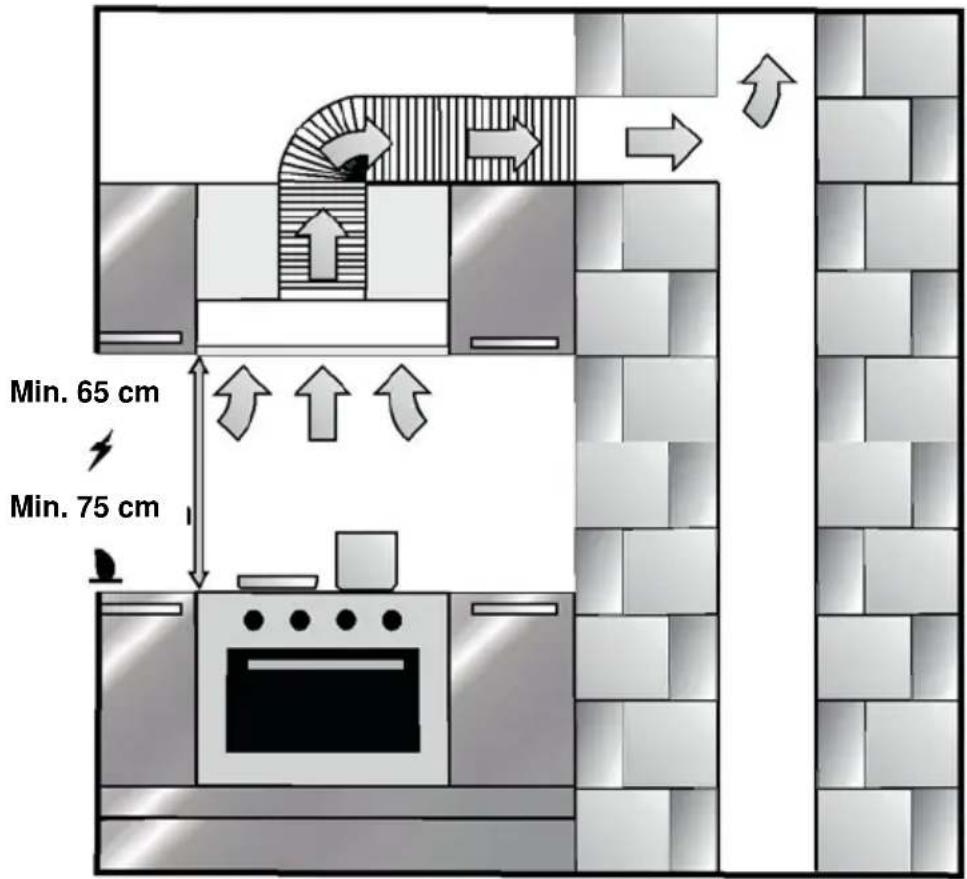
■ After the installation of the cooker hood, the minimum distance must be 65 cm between the product and any electric cooker; and 75 cm between it and any gas ranges or cookers burning other fuels.
■ Output of the cooker hood must not be connected to air ducts, where there exist another smokes.
■ You must be careful when using the appliance spontaneously with other appliances (e.g. gas, diesel fuels, coal or wood burning heaters, shower heaters, etc.) Attention must be paid when using them simultaneously. It is because the cooker hood could adversely affect the combustion, by discharging the ambient air.
■ This warning does not apply to uses without flue.
■ When electric cooker hood is used simultaneously with devices that use gas or other fuels, there must be sufficient ventilation in the room (might not apply to devices that discharges the air back into the room).
■ Simultaneous operation of more than one gas cooker leads to generation of high heat. A ventilation appliance placed on the surface of cookers might therefore get damaged or burn. Do not operate two gas cookers in high heat for more than 15 minutes. One large burner with more than 5kW (Work) power generates power equal to that of two gas burners.
2.1 Life-Threatening Danger, Poisoning Danger
DANGER
There are life-threatening danger and poisoning danger due to reabsorbed combustion gases. During the air discharge outlet use, unless sufficient air supply is provided, do not use the appliance simultaneously with devices that discharge toxic gases through flue such as ventilated, gas, oil, wood or coal burning heaters, shower heaters, water heaters, etc.
text_image
Safety warning symbol and diagram showing a skull hazard and a house with airflow arrowsFig. 2: Poisoning Danger
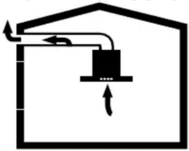
Ventilated devices (e.g. gas, oil, wood or coal burning heaters, shower heaters, water heaters) take combustion air from the installation location, and discharge the waste gas through a waste gas system (e.g. flue). When the cooker hood is active, it absorbs air from the kitchen and neighbouring rooms. If adequate air entry is not provided vacuum emerges. In such a case, the toxic gases are absorbed from the flue and waste gas channel, and are taken into to door again. Fig. 2 Therefore, adequate fresh air ingress must always be ensured. Fig. 3
natural_image
Simple line drawing of a house with airflow and fire symbol (no text or labels)Fig. 3
! DANGER
Fire danger!
Due to sparkling. Installation of appliance over a heating device that is heated by using solid fuels (for ex. wood or coal) is only allowed if an non-detachable cover is present. For the installation process, attention must be paid to current applicable construction regulations and regulations of local electric and gas companies. Appliance might lead to fire unless it is produced in accordance with cleaning instructions.
! DANGER
2.2 Danger of electric shock!
Do not bend or jam the connection cable during installation due to danger of damaged connection cable.
! DANGER
2.3 Danger of physical injury!
■ During the installation, there is a danger of physical injury due to the sharp edges. Use protective gloves throughout the installation process of the appliance.
■ Due to risk of dropping the appliance, assembly of all safety bolts and covers must be performed as specified in the user manual.

DANGER
2.4 Danger of burn, danger of electric shock!
■ Allow the appliance to cool before cleaning or maintenance process. Switch off the fuse or pull out the mains plug from the socket.
■ There is risk of damage due to ingress of moisture in the electronics. Do not clean the control components with a wet cloth.
■ The surface could be damaged due to a wrong cleaning process. Clean stainless steel surfaces only in their brushing direction. Do not use a stainless steel cleaner for the control elements.
■ The surface could be damaged due to aggressive and abrasive cleaning agents. Never use aggressive and abrasive cleaning agents.
■ There is risk of damage due to backflow of condensate. Mount the air outlet channel downwards from the appliance (slope of 1°).

DANGER
2.5 Dangers of fire and physical injury!
In case of repairing that is not performed according to the rules or as required, turn off the fuse or unplug the feeder cable of your appliance. Repairing must be performed only by the authorized technical service or authorized experts.
NOTE
If the appliance is faulty or damages, turn off the fuse or unplug the feeder cable of your appliance and call the authorized service.
NOTE
If the feeder cable is damaged, it must be replaced by its manufacturer or its authorized technical service or any other personnel qualified at the same level, in order to avoid any dangerous situation.
NOTE
If the bulbs of your appliance are faulty, turn off the fuse or unplug the feeder cable of your appliance. Replace the bulbs immediately to avoid overload on other bulbs (wait for the bulbs to cool down first)

ATTENTION
Accessible components might be heated when used with cooking devices.

DANGER
Air outlet pipe of this appliance mustn't be connected in the flue used to discharge the fume generated by devices that use gas or other fuels.
3 USAGES WITH AND WITHOUT CARBON USE
You can use this appliance in exhaust air mode and ventilated air mode.
Exhaust air mode
The absorbed air is cleaned by the grease filters and is discharged through a piping system. 4
natural_image
Simple line drawing of a house with a central box and airflow arrows (no text or symbols)Fig. 4: Air Outlet without Carbon Filter
DANGER
Death Risk!

Exhaust gases that are reabsorbed might lead poisoning Exhaust air must not be transferred to an active smoke or waste gas flue; or a flue used for ventilation of the places, where heat sources are installed.
■ If you want to transfer exhaust air to an inactive centre. smoke or waste gas flue, you need to obtain permission from an authorized chimney sweep.
■ If exhaust air is discharged through the external wall, a telescopic wall safe must be used.
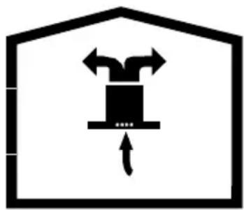
Ventilated air mode

Absorbed air is cleaned by the grease filters and an active carbon filter, and then it is transferred back to the kitchen. 5
natural_image
Simple line drawing of a box inside a house-shaped frame with arrows indicating movement (no text or symbols)Fig. 5: Air Outlet with Carbon Filter

To retain the substances that lead to odour in ventilated air mode, you must attach an active carbon filter. Consult your authorized dealer for various options available to use your appliance in ventilated air mode. You can purchase the accessories required for this process for related sales points, authorized services or online sales
3.1 Replacement of Carbon Filter
In environments without flue, active carbon filter must be used for filtering the air and resending it in. Active carbon filter must be supplied from service or your dealer. De-energize the appliance before replacing the carbon filter. Since carbon filter is used in kitchens with no flue outlet, it must be replaced in every 3-5 months depending on the use.
Carbon filter must never be washed. Grease filters must be installed in the product, regardless of whether or not carbon filters are used. Do not use your product without grease filter.
3.2 Replacement of AF 90 Carbon Filter
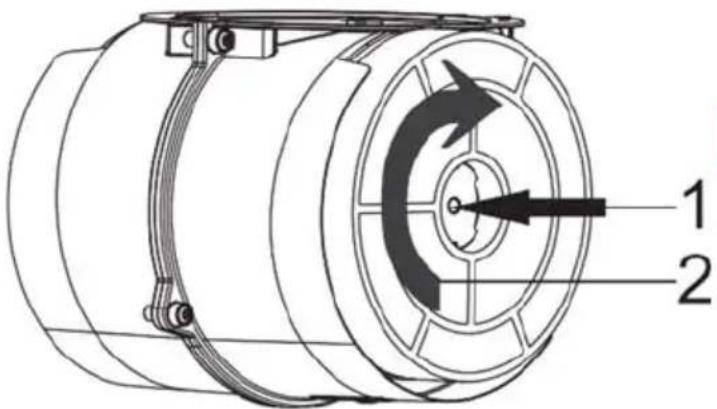
text_image
Technical diagram of a mechanical component with labeled parts 1 and 2, showing directional arrows indicating motion or flow.Fig. 6: AF 90 CARBON FILTER
The appliance you have purchased is appropriate for use with AF 90 carbon filters.
- Place the carbon filter in its housing. Fig. 6
- Rotating the carbon filter clockwise, ensure that it is completely fit. Fig. 6

If carbon filter does not fit in
completely, it might drop and damage your product.
3.3 Replacement of AF 100 Carbon Filter
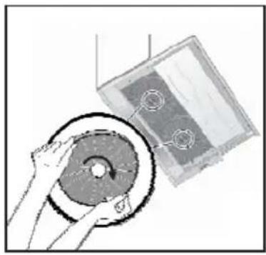
natural_image
Illustration of a hand holding a circular component next to a rectangular device (no text or symbols visible)Fig. 6: AF 100 CARBON FILTER
The appliance you have purchased is appropriate for use with AF 100 carbon filters.
- Place the carbon filter in its housing. Fig. 6
- Rotating the carbon filter clockwise, ensure that it is completely fit. Fig. 6

DANGER
Do not wash carbon filters. Keep the carbon filters away from children.
4 CLEANING AND PREVENTIVE MAINTENANCE
ATTENTION
■ Prior to each maintenance and cleaning, cooker hood must be unplugged, and appliance must be dead
■ Cleaning and user maintenance of the appliance shall not be performed by unattended children.
■ The surface could be damaged due to aggressive and abrasive cleaning agents. Never use aggressive and abrasive cleaning agents.
Supply your cleaning and protective substances that are appropriate for your appliance from the authorized technical service. Surface of appliance and control units are sensitive to scratching.
■ Clean the surfaces with a soft and damp cloth, dish-washing liquid or mild glass cleaning agent. Soften the dry, sticky dirt with a damp cloth. Do not scrape!
■ It is not appropriate to use dry cloths, sponges that may scratch, materials that require rubbing, and other aggressive cleaning agents containing sand, soda, acid or chlorine.
■ Clean the stainless steel surfaces in their brushing direction only.
■ Do not use stainless steel cleaning agents and wet clothes for control units. Cleaning of metal grease filters Used metal grease filters retain the greasy particles in the moisture and vapour generated in the kitchen. Clean the metal grease filters about every three months, under normal use conditions (1 to 2 hours a day).
■ Do not use excessively effective, acidic or alkaline cleaning agents.
■ For cleaning the metal grease filters, clean the holder parts of the metal grease filters in the appliance, with a damp cloth as well.
■ You can clean the metal grease filters in the dishwasher or by hand.
4.1 Washing in Dishwasher
In case of washing in dishwasher, a slight change might occur in colour. This has no effect on the function of the metal grease filter.
■ Do not wash the excessively dirty metal grease filters together with dishes.
■ Place the metal grease filters loosely and freely in the dishwasher. Metal grease filters must be placed in the dishwasher without jamming.
4.2 Hand Wash
For stubborn dirts, you can use a special grease solvent. You can buy such an agent from the authorized sales centre.
■ Soften the metal grease filters in a hot water with dish-washing liquid.
■ Use a brush for cleaning and wait for the liquid in metal grease filters to flow off completely.
■ Rinse the filters thoroughly after cleaning.
ATTENTION
Thanks to timely cleaning of metal grease filter, the fire danger caused by excessive heat that is generated during frying is avoided.
4.3 Removal/Installation of Aluminium Filter
Pull the aluminium filter towards you by pressing on its tab. Reverse the process to install the filter.
5 INSTALLATION OF APPLIANCE
text_image
Min. 65 cm Min. 75 cmFig. 7: INSTALLATION OF APPLIANCE
After completing the installation of cooker hood, the minimum distance must be 650 mm between the product and any electric cooker; and 750 mm between it and any gas ranges or cookers burning other fuels. Fig. 7
5.1 Installation and Unpacking of the Appliance
Check that your appliance is not deformed.
■ Report the transport issues immediately to transport operator.
■ Any faults encountered shall be reported to the dealer, too.
■ Do not allow children to play the with packaging materials !!!
5.2 Installation and Unpacking of the Appliance
■ Replace the carbon filters on a regular basis.
■ Regularly clean your aluminium filters. Since dirty filters would block the air passage, you might have to use the appliance at a higher speed.
■ Use your product according to its normal speeds.
■ Use at higher speed would cause an increase in the energy consumption.
5.3 Exhaust Air Mode
DANGER
Death Risk!
Exhaust gases that are reabsorbed might lead to poisoning. Exhaust air must not be transferred to an active smoke or waste gas flue; or a flue used for ventilation of the places, where heat sources are installed. If you want to transfer exhaust air to an inactive smoke or waste gas flue, you need to obtain permission from an authorized chimney sweep.
If exhaust air is discharged over the external wall, a telescopic wall case must be used.
5.4 Air Discharge Line
Information: Manufacturer of appliance cannot be held responsible for defects caused by laid pipes.
■ Appliance shows the highest performance when a short and flat air outlet pipe and a pipe diameter as large as possible is used.
■ Optimum ventilation performance cannot be reached and noise of fan increases when long and rough air outlet pipes and multiple pipe elbows or pipe diameters smaller than 150 mm are used.
■ Pipes or hoses used in laying the air outlet line must be made of inflammable materials.
Circular Pipes
It is recommended that inner diameter should be 150 mm or at least 120 mm.
Flat Channels
Inner Section must be appropriate to the diameter of circular pipes.
∅150 mm approx. 177 cm²
∅120 mm approx. 173 cm ^2
■ Flat channels shouldn't have sharp elbows.
■ Use sealing strips for different pipe diameters.
5.5 Checking the Wall
■ Wall must be flat, straight and have the sufficient bearing capacity.
■ Depth of drilling holes must comply with the length of bolts. Dowels must fit in properly.
■ Bolts and dowels in the enclosure are appropriate for use in rigid monolithic walls. Use appropriate fasting materials for different constructions (for ex. plasterboard, aerated concrete, proton bricks).
5.6 Electrical Connection
DANGER
Electric Shock Danger!
Components in the appliance might have sharp edges. Connection cable can be damaged. Do not bend or jam the connection cable during installation.
Necessary connection data is provided on the type label found inside your appliance; metal grease filters must be removed to see the label.
Length of connection line: approx. 1.3 m
This appliance complies with EU interference elimination guidelines.
! DANGER
5.7 Danger of Electric Shock!
It must always be possible to disconnect the appliance from the electric network. Appliance must be plugged in a protected contact outlet that is mounted in accordance with the rules. If the plug cannot be reached after installation or during the required fixed connection, there must be many pole separation assemblies available with at least 3 mm contact distance to the installation. Fixed connection must be performed by an electronics expert only.
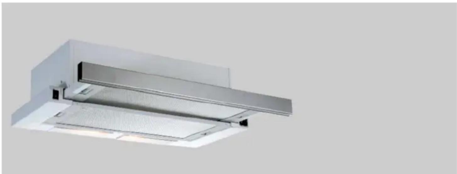
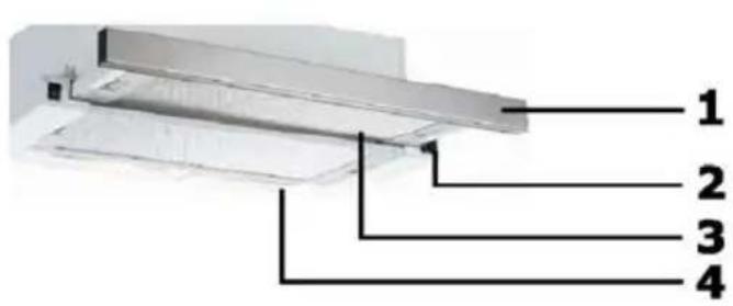
6 OVERVIEW OF APPLIANCE
text_image
1 2 3 4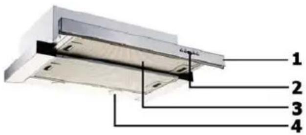
text_image
1 2 3 4Fig. 9: OVERVIEW OF COOKER HOOD
- Front Panel
- Key
- Filter
- Lighting
7 ASSEMBLY OF PRODUCT
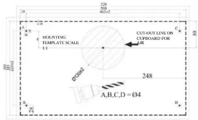
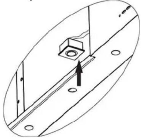
Drilling the Hanger Holes
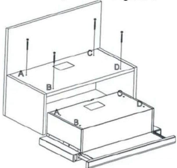
Make holes with ∅4 mm diameter on the points marked as A, B, C, D on the mounting scheme.
Figure 2
text_image
520 500 462x2 A E R MOUNTING TEMPLATE SCALE 1:1 CUT-OUT LINE ON CUPBOARD FOR AIR Ø130±2 248 A,B,C,D = Ø4 B D 28 20 22±2 80Figure 2
The appliance should be mounted on the cabinet on the points A, B, C, D by using 4 x 40 screws provided with the appliance. The front panel should not be rubbed against the cabinet cover when the sliding set moves. Figure 3
text_image
A B C D A B C DFigure 3
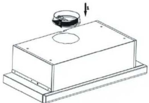
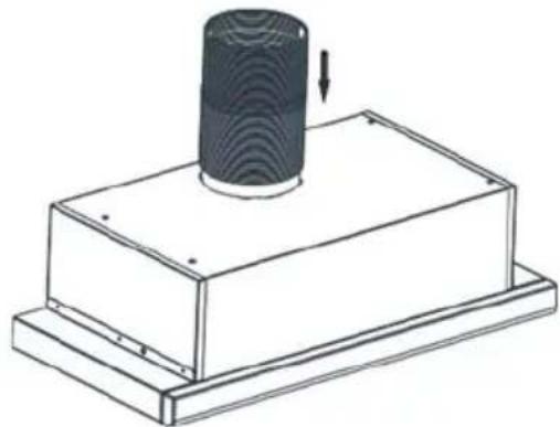
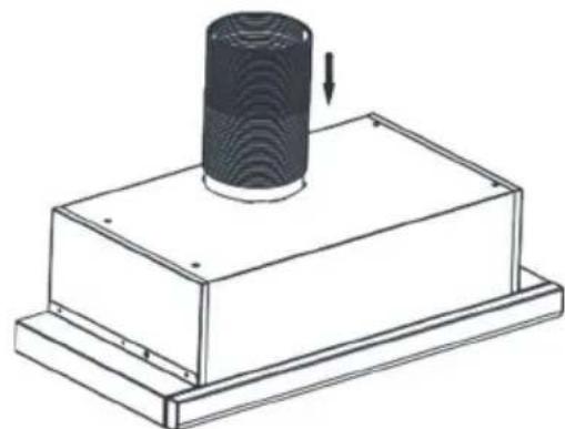
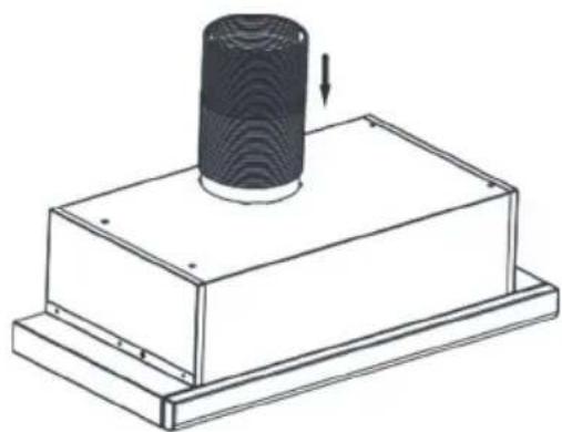
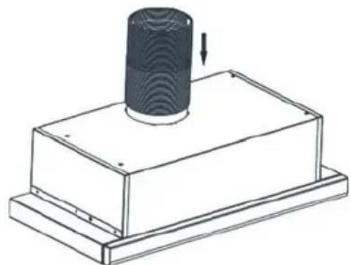
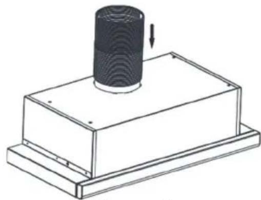
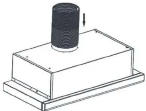
Place the plastic flue provided with the appliance on the flue outlet on the appliance. Rotate the plastic flue clockwise. Figure 4 Install flexible aluminium pipe to plastic flue outlet. Install the other end of the pipe to the flue hole on the wall. Figure 5
natural_image
Technical line drawing of a mechanical housing with a circular component and a downward arrow indicator (no text or symbols)Figure 4
natural_image
Technical line drawing of a mechanical assembly with a cylindrical component and base plate (no text or symbols)Figure 5
ATTENTION
Since twists and bends in the aluminium pipe will lead to reduction in the air suction power, avoid using twists and bends as much as possible.
Functions of Device
Cooker hood is used in kitchens with or without flue.
In case of use with flue;
In flue-connected use, cooker hood must be connected to a flue that will discharge the air. Prefer the shortest way for the pipe system that leads to flue, in order to get the maximum efficiency from your cooker hood. Your product is manufactured in a form appropriate for use with flue.
8 USE OF PRODUCT
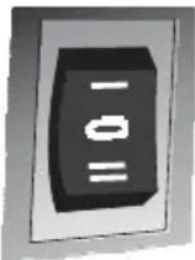
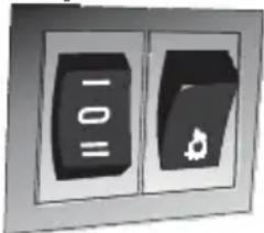
3 Spd Rocker Switch

natural_image
Simple black-and-white diagram of a rocket inside a rectangular frame (no text or symbols)Lamp Switch
Turn the switch to lamp position to turn on the light of the appliance. The sliding set must be detached to turn on lights.
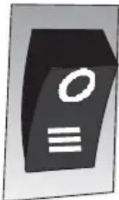
3. Circulation Switch
text_image
-10 =0If you want to run the appliance at the third speed move the switch down.
3. Circulation Switch
natural_image
Abstract 3D icon of a black rectangular object with white circular and horizontal lines, resembling a stylized letter or symbol (no text or numbers present)If you want to run the appliance at the third speed move the switch down.
2 Spd Rocker Switch
natural_image
Two black rectangular buttons with symbols, one labeled '10' and the other a leaf icon (no readable text or numbers)The product has 2 lamps and a switch to control lighting. The sliding set must be detached to turn on lights.
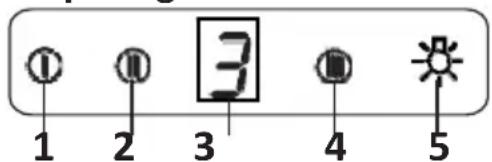
3 Spd Dgt Switch
text_image
① ② ③ ④ ⑤ 1 2 3 4 51- Press this button when you want to operate the product in speed 1.
2- Press this button when you want to operate the product in speed 2.
3- Press this button when you want to operate the product in speed 3.
4- Press this button when you want to turn on the product lights.
Speed Selection
Appliance has is a 3-level ventilation. One of the low-medium-high ventilation levels is selected according to cooking and frying vapour. It is started by pressing the motor control buttons on the front panel. Electronic controlled models have automatic timer.
Timer
If you press any of the motor starting buttons for longer than 2 seconds, a timer function shall activate with 15 minutes duration. Display shall also give a signal when the timer starts and the motor shall stop automatically 15 minutes later.
Cleaning Periods of the Metal Filter:
The filters must be cleaned when "C" signal appears on the display or (depending on usage) after every 2-3 weeks. When the filters are cleaned and mounted in their places, press button (① for more than 3 seconds in order to delete "C" signal (when the product is inactive). Letter "E" will appear on the display, and the product will switch to normal operation. If the operation is desired to continue without deleting "C" signal, when you push on (① button, active operation will be observed for 1 sec. and then "C" signal will reappear and the motor will continue to run.
ATTENTION
"C" mark will appear at the end of the product's usage period of 60 hours.
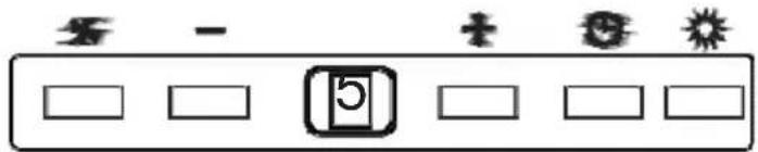
5 Spd Dgt Switch
text_image
Diagram showing a control panel with icons for alarm, display, and sun symbolsATTENTION
"C" mark will appear at the end of the product's usage period of 60 hours.

On-Off: The appliance will start once this button is pressed.

Decreasing Speed: Speed will decrease if this button is pressed.

Increasing Speed: Speed will increase if this button is pressed.

Timer: When the button is pushed on, a timing function is activated for a period of 15 minutes, and once the timing starts, also the display gives a signal, and the motor stops automatically after 15 minutes.

Lamp: The lamp will turn on once the button is pressed. Re-press the button to turn off the lamp.
Cleaning Periods of the Filters:
The filters must be cleaned when "c" signal appears on the display or (depending on usage) after every 2-3 weeks. When the filters are cleaned and mounted in their places, press button for more than 3 seconds in order to delete "c" signal (when the product is inactive). Letter "E" will appear on the display, and the product will switch to normal operation. If the operation is desired to continue without deleting "c" signal, when you push on (×button, active operation will be observed for 1 sec. and then "C" signal will reappear and the motor will continue to run.
NOTE: "c" mark will appear at the end of the product's usage period of 60 hours.
Efficient Use With Regard to Energy Saving:
* When using your hood, adjust the speed settings according to vapour and odour intensity, in order to save energy.
* Use low speeds (1-2) under normal conditions, and high speeds (3) in intense odour and vapour.
* The lamps on the hood are placed for illuminating the cooking area.
Using them for environmental lighting shall cause unnecessary energy expenditure and insufficient lighting.
Use of Hood:
* Your hood contains a motor that has various speeds.
9 REPLACEMENT OF LAMPS

DANGER
Disconnect the electrical supply of the cooker hood. Leave the lamps to cool down first because they could burn your hands when they are hot.
9.1 Replacement of Halogen Lamp
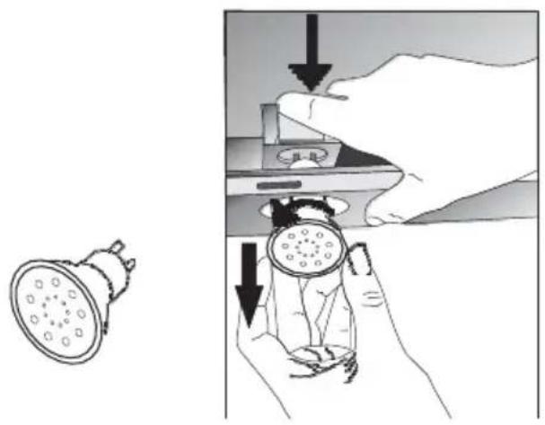
natural_image
Illustration showing a showerhead being held by hands, with no text or symbols present.Fig. 13: Replacement of LED Lamp
Remove the aluminium cartridge filter. Remove the faulty bulb and replace with a new one with the same rating. Fig. 13
9.2 Replacement of Spark Plug Lamp
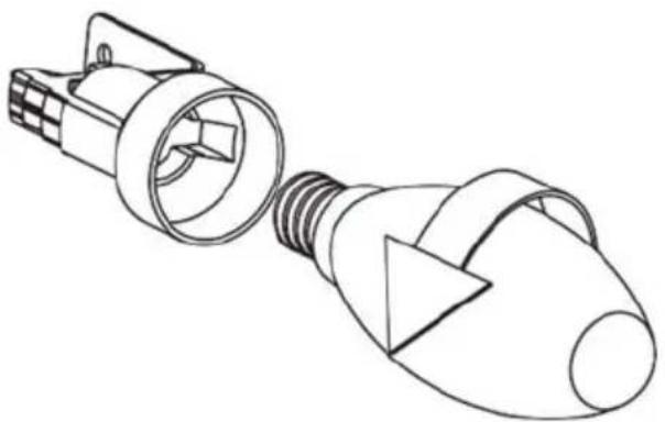
natural_image
Line drawing of two types of light bulbs with no text or symbolsFig. 14: Replacement of Spark Plug Lamp
Remove the aluminium cartridge filter. Remove the faulty bulb and replace with a new one with the same rating. Fig. 14
9.3 1W Replacement of LED Lamp
natural_image
Technical diagram showing a mechanical assembly with a central bolt and mounting holes, no text or symbols present.- Disconnect the electrical connection of LED lamp.
- Push on the lamp with your hand, to remove it.
- Separate the self adhesive tape around the lamps and the body plate from each other.
- Before placing the new LED lamp, remove the protective folio from the frame, and then stick it on its place on the body of the product.
10 AUTHORIZED TECHNICAL SERVICE
If Lighting is Not Functioning:
■ Make sure that the plug is plugged in, and that the fuses are intact.
- Check the bulbs. Make sure you unplugged the device before performing this check. Tighten the bulbs if they are loose; you can replace the bulbs if they still doni work.
Possible Faults and What-to-Do Before Calling the Technical Service:
A) If the appliance does not work in any way:
- Check to see if the cooker hood is plugged in or if the plug is fit properly into the socket.
■ Check the fuse, to which the appliance is connected, as well as the main fuse of your house.
If the performance of appliance is insufficient or it operates with too much noise:
■ Is the outlet diameter of the appliance's flue adequate? (min.120 mm).
■ Are the metal filters clean? Please check.
■ If you use the cooker hood without flue, make sure that the carbon filters are not older than 6 months.
■ Be attentive to ventilate your kitchen adequately, in order to provide an airflow. If you are still not satisfied with the performance of the appliance, consult the authorized technical service.
10.1 Potential Failures and Solutions
| Description of Failure | Reason | Help |
| Appliance Does Not Work. | Check the power connection. | Mains voltage must be 220-240 V, and product must be plugged into a grounded socket. |
| Lighting Lamp Does Not Operate. | Check the power connection. | Mains voltage must be 220-240 V, and product must be plugged into a grounded socket. |
| Lighting Lamp Does Not Operate. | Check the power connection. | Lamp switch must be at "on" position. |
| Lighting Lamp Does Not Operate. | Check the bulbs. | Bulbs must be operative. |
| Product's Air Intake is Weak. | Check the aluminum filter. | The aluminum cartridge filter should be washed once a month under normal conditions. |
| Product's Air Intake is Weak. | Check the air outlet flue. | Air Outlet Flue Must Be Open. |
| Product's Air Intake is Weak. | Check the carbon filter. | In products that work with carbon filters, carbon filter must be replaced once in every 3 months under normal conditions. |
| It Does Not Discharge Air (in flueless use) | Check the aluminum filter. | The aluminum cartridge filter should be washed once a month under normal conditions. |
| It Does Not Discharge Air (in flueless use) | Check the carbon filter. | In products that work with carbon filters, carbon filter must be replaced once in every 3 months under normal conditions. |
10.2 Technical Table
| Supply Voltage | 220 - 240 V 50Hz |
| Insulation Class of Motor F | |
| Insulation Class | CLASS I |
CANDY
HOTTE DE CUISSON MANUEL D'INSTRUCTIONS
CBT9240/2X
CBT6324/1X
CBT6324/1W
CBT6324/1N
CBT6130/2X
CBT6240/1LN
CBT6240/1LW
CBT6240/1LX
natural_image
Exterior view of a modern kitchen air duct with ventilation grilles and ventilation grilles (no text or symbols visible)* PCB = Printed Circuit Board
1 DESSIN TECHNIQUE
text_image
500 280 40136 M n 305 Max 475 899 CBT9240/2X
text_image
280 223 78.2 499 462 6 20 R 600 20 27 283 Max425 Min305 ACBT6324/1X
CBT6324/1W
CBT6324/1N

text_image
100 130 116 40 Min300-Men430 800CBT6130/2X
CBT6240/1LN
CBT6240/1LW
CBT6240/1LX
text_image
Safety warning symbol and diagram showing a skull hazard and electrical circuit with smokestacknatural_image
Simple line drawing of a house with airflow indicators and a checkmark (no text or symbols)Fig. 3
DANGER
Danger d'incendie !
natural_image
Simple line diagram of a house with a central box and directional arrows, no text or symbols present.natural_image
Symbolic icon of a box inside a house outline, with arrows indicating direction (no text or labels)text_image
Technical diagram of a mechanical device with labeled parts 1 and 2, showing internal components and directional arrows.natural_image
Illustration of a hand holding a circular component next to a rectangular device (no text or symbols visible)7 ASSEMBLAGE DU PRODUIT
natural_image
Technical line drawing of a mechanical component with a circular feature and a downward arrow indicator (no text or symbols)Figure 4

natural_image
Technical line drawing of a mechanical assembly with a cylindrical component and base plate (no text or symbols)Figure 5
ATTENTION
natural_image
Simple black-and-white diagram of a rocket inside a rectangular frame (no text or symbols)natural_image
Close-up of a black rectangular electronic component with three horizontal white lines and one vertical line, no visible text or symbols.natural_image
Simple 3D icon of a folder with an 'O' and three horizontal lines below (no text or symbols)text_image
Diagram showing a control panel with symbols for alarm, battery, and sun, alongside blank input boxes.ATTENTION
natural_image
Illustration showing a showerhead being held by hands, with no text or symbols present.natural_image
Line drawing of two light bulbs with screw heads and bulb ends, no text or symbols presentnatural_image
Technical line drawing of a mechanical assembly with a central component and mounting holes (no text or symbols)10.2 Tableau technique
natural_image
Exterior view of a modern kitchen ventilation duct (no text or symbols visible)* PCB = Printed Circuit Board
1 DISEGNO TECNICO
text_image
500 280 401.76 M n 305 Max 475 899CBT9240/2X
text_image
280 222 78.5 499 462 600 20 27 283 Max625 Min305 ACBT6324/1X
CBT6324/1W
CBT6324/1N
text_image
1/6 40 M1x305-Mgn470 100 30 600CBT6130/2X
CBT6240/1LN
CBT6240/1LW
CBT6240/1LX
Fig. 1: DISEGNO TECNICO
text_image
Safety warning symbol and diagram showing a skull inside a triangular warning triangle and a gas stove with flame, indicating hazard or hazard.natural_image
Simple line drawing of a house with airflow indicators and a checkmark (no text or symbols)Fig. 3
PERICOLO
natural_image
Simple line diagram of a house with a central box and directional arrows indicating airflow or movement (no text or symbols)natural_image
Simple line drawing of a box inside a house-shaped frame with arrows indicating direction (no text or symbols)text_image
Technical diagram of a mechanical device with labeled parts 1 and 2, showing internal components and directional arrows.Fig. 6: FILTRO AL CARBONE AF 90
natural_image
Illustration of a hand holding a circular object next to a rectangular panel with circular markings (no text or symbols)Fig. 6: FILTRO AL CARBONE AF 100
natural_image
Technical line drawing of a mechanical component with a circular feature and a downward arrow indicator (no text or symbols)Figura 4
natural_image
Technical line drawing of a mechanical component with a cylindrical top and base, showing a downward arrow indicating motion (no text or symbols)Figura 5
ATTENZIONE
natural_image
Simple black-and-white diagram of a 3D object with a small white figure inside, enclosed in a rectangular frame (no text or symbols)Interruttore luce
natural_image
Simple 3D icon of a computer monitor with 'O' and three horizontal lines below (no text or symbols)natural_image
Two black rectangular buttons with symbols, one labeled '10' and the other a small icon (no readable text or numbers)text_image
Diagram showing a control panel with symbols for alarm, battery, and sun, alongside blank input boxes for display.ATTENZIONE
natural_image
Illustration showing a showerhead being lowered and held by hands, with no text or symbols present.natural_image
Line drawing of two light bulbs with internal components, no text or symbols presentnatural_image
Technical line drawing of a mechanical assembly with a central component and mounting holes (no text or symbols)natural_image
Exterior view of a modern kitchen air duct with ventilation grilles and ventilation grilles (no text or symbols visible)1 RYSUNEK TECHNICZNY 60
* PCB = Printed Circuit Board
1 RYSUNEK TECHNICZNY

text_image
400 280 40135 M n 305 Max 475 890 CBT9240/2X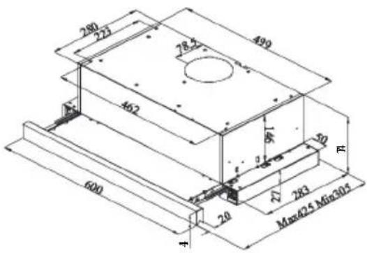
text_image
280 223 78.2 499 462 6 20 R 600 20 27 283 Max425 Min305 ACBT6324/1X
CBT6324/1W
CBT6324/1N

text_image
100 130 116 40 Min300-Men430 800CBT6130/2X
CBT6240/1LN
CBT6240/1LW
CBT6240/1LX
Rys. 1: RYSUNEK TECHNICZNY
text_image
Safety warning symbol and schematic diagram showing a skull hazard inside a triangular warning triangle and a house with electrical circuit lines.natural_image
Simple line drawing of a house with airflow indicators and a checkmark (no text or symbols)Rys. 3
NIEBEZPIECZEŃSTWO
natural_image
Simple line diagram of a house with a central box and directional arrows, no text or symbols present.natural_image
Symbolic icon of a box inside a house outline, with arrows indicating direction (no text or numbers present)text_image
Technical diagram of a mechanical device with labeled parts 1 and 2, showing internal components and directional arrows.Rys. 6: FILTR WĘGLOWY AF 90
natural_image
Illustration of a hand holding a circular object next to a rectangular device with circular components (no text or symbols visible)Rys. 6: FILTR WĘGLOWY AF 100
natural_image
Technical line drawing of a mechanical component with a circular feature and downward arrow (no text or symbols)Rysunek 4
natural_image
Technical line drawing of a mechanical component with a cylindrical top and base, showing a downward arrow indicating motion (no text or symbols)Rysunek 5
⚠️ UWAGA
natural_image
Abstract geometric shape with a small white star-like symbol inside a dark frame (no text or symbols)text_image
Close-up of a black rectangular electronic component with white markings, likely a button or indicator.natural_image
Simple icon of a computer monitor with 'O' and three horizontal lines below (no text or symbols)text_image
Diagram showing a sequence of icons including '5', '1', '2', and '3' with corresponding blank boxes below, likely representing a timer or timer.⚠️ UWAGA
text_image
Diagram illustrating the process of using a showerhead to adjust its interior, with Chinese annotations indicating steps and directional arrows.natural_image
Line drawing of two types of fluorescent bulbs with internal components (no text or symbols)natural_image
Technical line drawing of a mechanical assembly with a central component and mounting holes (no text or symbols)natural_image
3D rendering of a stainless steel kitchen ventilation duct (no text or symbols visible)8 USO DEL PRODUCTO....91
* PCB = Printed Circuit Board
1 ESQUEMA TÉCNICO
text_image
500 280 401.36 M n 305 Max 475 899CBT9240/2X
text_image
280 273 78.2" 490 460 600 20 Max Q5 Min305 27 243 3 4CBT6324/1X
CBT6324/1W
CBT6324/1N
text_image
100 30 1/6 40 Min305-Max420 600CBT6130/2X
CBT6240/1LN
CBT6240/1LW
CBT6240/1LX
Fig. 1: ESQUEMA TÉCNICO
text_image
Safety warning symbol and diagram showing a skull hazard and a gas stove with airflow arrowsnatural_image
Simple line drawing of a house with airflow indicators and a checkmark (no text or symbols)Fig. 3
PELIGRO
Peligro de incendio
natural_image
Simple line diagram of a house with a central box and directional arrows, no text or symbols present.Fig. 4: Salida de aire sin filtro de carbón
PELIGRO
Riesgo de muerte

natural_image
Simple line drawing of a box inside a hexagonal frame with arrows indicating direction (no text or symbols)text_image
Technical diagram of a mechanical component with labeled parts 1 and 2, showing internal flow direction indicated by arrows.natural_image
Illustration of a hand holding a circular object next to a rectangular panel with circular markings (no text or symbols)text_image
Technical diagram of a two-tiered storage unit with labeled components A, B, C, D and vertical supportsFigura 3
natural_image
Technical line drawing of a mechanical component with a circular feature and a downward arrow indicator (no text or symbols)Figura 4
natural_image
Technical line drawing of a mechanical component with a cylindrical top and base, showing a downward arrow indicating motion (no text or symbols)Figura 5
ATENCIÓN
natural_image
Simple black-and-white diagram of a device with a triangular component and a small white symbol inside (no text or labels)natural_image
Close-up of a black rectangular electronic component with three horizontal lines (one labeled '1', one '2') on its surface, no readable text or symbols.natural_image
Simple 3D icon of a computer monitor with 'O' and three horizontal lines below (no text or symbols)natural_image
Two black rectangular buttons with symbols, one labeled '100' and the other a small icon (no readable text or numbers)text_image
Control panel with icons for alarm, battery, and sun symbolsATENCIÓN
natural_image
Illustration showing a showerhead being held by hands, with no text or symbols present.natural_image
Line drawing of two types of light bulbs with no text or symbolsnatural_image
Technical line drawing of a mechanical assembly with a central component and mounting holes (no text or symbols)EXAUSTOR MANUAL DE INSTRUÇÕES
CBT9240/2X
CBT6324/1X
CBT6324/1W
CBT6324/1N
CBT6130/2X
CBT6240/1LN
CBT6240/1LW
CBT6240/1LX

natural_image
Exterior view of a modern kitchen air duct with ventilation grilles and ventilation grilles (no text or symbols visible)1 ESQUEMAS TÉCNICOS....98
2 AVISOS E PRECAUÇÕES DE SEGURANÇA 99
2.1 Risco de vida, risco de envenenamento ..... 101
* PCB = Printed Circuit Board
1 ESQUEMAS TÉCNICOS
text_image
500 280 40134 M n 305 Max 475 899CBT9240/2X

text_image
280 223 462 600 20 78.5 490 50 R 27 283 Max425 Min305CBT6324/1X
CBT6324/1W
CBT6324/1N

text_image
100 30 1.16 40 Mdn309-Mdn470 600CBT6130/2X
CBT6240/1LN
CBT6240/1LW
CBT6240/1LX
Fig. 1: ESQUEMAS TÉCNICOS
2 AVISOS E PRECAUÇÕES DE SEGURANÇA
text_image
Safety warning symbol and diagram showing a skull inside a triangular warning triangle and a house with airflow arrows and smoke.Fig. 2: Perigo de envenenamento
natural_image
Simple line drawing of a house with airflow and fire symbol (no text or labels)Fig. 3
PERIGO
Risco de incêndio!
natural_image
Simple line diagram of a house with a central box and directional arrows, no text or symbols present.Fig. 4: Saída de ar sem filtro de carbono
PERIGO
Perigo de morte!

natural_image
Simple line icon of a box inside a house outline, with arrows indicating direction (no text or symbols)Fig. 5: Saída de ar com filtro de carbono

text_image
Technical diagram of a mechanical component with labeled parts 1 and 2, showing internal flow or movement arrows.Fig. 6: FILTRO DE CARBONO AF 90
natural_image
Illustration of a hand holding a circular object next to a rectangular device with circular components (no text or symbols visible)Fig. 6: FILTRO DE CARBONO AF 100
natural_image
Line drawing of a two-tiered storage unit with labeled sections A, B, C, D and support fixtures (no text or symbols beyond labels)Figura 3
Coloque a chaminé plástica fornecida com o aparelho na saída para a chaminé no aparelho. Rode a chaminé de plástico para a direita.
Figura 4
natural_image
Technical line drawing of a mechanical component with a circular feature and a downward arrow indicator (no text or symbols)Figura 4
natural_image
Technical line drawing of a mechanical assembly with a cylindrical component mounted on a base plate (no text or symbols)Figura 5
ATENÇÃO
natural_image
Simple 3D-rendered object with a white flower-like symbol inside, enclosed in a dark rectangular frame (no text or symbols)natural_image
Abstract 3D icon of a computer monitor with 'O' and three horizontal lines (no text or symbols)text_image
Diagram showing a control panel with symbols for alarm, display, and warning signs⚠️ ATENÇÃO
natural_image
Illustration showing a showerhead being held by hands, with no text or symbols present.natural_image
Line drawing of two light bulb components with no text or symbolsnatural_image
Technical line drawing of a mechanical assembly with a central component and mounting holes (no text or symbols)natural_image
Exterior view of a modern kitchen ventilation duct (no text or symbols visible)1 TECHNICKÉ VÝKRESY 117
2 VAROVÁNÍ A BEZPEČNOSTNÍ OPATŘENÍ....118
* PCB = Printed Circuit Board
1 TECHNICKÉ VÝKRESY

text_image
500 280 40136 M n 305 Max 475 899CBT9240/2X

text_image
280 222 78.5 499 462 600 20 27 283 Max625 Min305 A RCBT6324/1X
CBT6324/1W
CBT6324/1N
text_image
M1x305-Mgn420 1/6 40 30 300CBT6130/2X
CBT6240/1LN
CBT6240/1LW
CBT6240/1LX
Obr. 1: TECHNICKÉ VÝKRESY
2 VAROVÁNÍ A BEZPEČNOSTNÍ OPATŘENÍ
text_image
Safety warning symbol and electrical circuit diagram showing a skull hazard and a device with flameObr. 2: Nebezpečí otravy
natural_image
Simple line icons showing a checkmark and a house with airflow arrows (no text or symbols)Obr. 3
NEBEZPEČÍ
Nebezpečí požáru!
natural_image
Simple line diagram of a house with a central box and airflow arrows (no text or symbols)natural_image
Simple line drawing of a box inside a house-shaped frame with arrows indicating movement (no text or symbols)text_image
Technical diagram of a mechanical component with labeled parts 1 and 2, showing directional arrows indicating motion or flow.Obr. 6: UHLÍKOVÝ FILTR AF 90
natural_image
Illustration of a hand holding a circular disc next to a rectangular device (no text or symbols visible)Obr. 6: UHLÍKOVÝ FILTR AF 100
natural_image
Line drawing of a two-tiered storage unit with labeled sections A, B, C, D and support fixtures (no text or symbols beyond labels)Obrázek 3
natural_image
Technical line drawing of a mechanical component with a circular feature and downward arrow indicator (no text or symbols)Obrázek 4
natural_image
Technical line drawing of a mechanical component with a cylindrical top and base, showing a downward arrow indicating motion (no text or symbols)Obrázek 5
⚠ UPOZORNĚNÍ
natural_image
Simple black-and-white diagram of a 3D object with a white figure inside, enclosed in a rectangular frame (no text or symbols)Spínač lampy
natural_image
Abstract 3D icon of a document or folder with three horizontal lines and a central oval (no text or symbols)natural_image
Two black rectangular buttons with white symbols, one labeled '10' and the other a flame icon (no readable text or numbers)text_image
Diagram showing a control panel with icons for alarm, battery, and sun symbols, featuring a labeled button '5' inside.⚠ UPOZORNĚNÍ
natural_image
Illustration showing a showerhead being adjusted for a showerhead inside a shower tube, with no text or symbols present.natural_image
Line drawing of two light bulb components with no text or symbolsnatural_image
Technical diagram of a mechanical assembly with a central bolt and mounting holes, showing alignment lines (no text or symbols)natural_image
Exterior view of a modern kitchen air duct system (no text or symbols visible)1 TECHNICKÝ NÁKRES 136
2 UPOZORNENIA A BEZPEČNOSTNÉ OPATRENIA 137
* PCB = Printed Circuit Board
1 TECHNICKÝ NÁKRES
text_image
400 280 401.56 M.p.305 Max.475 899 CBT9240/2X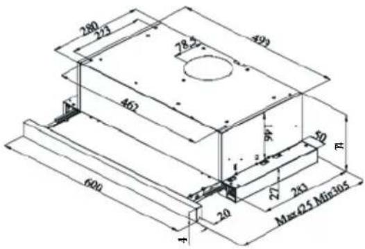
text_image
280 273 493 78.27 462 600 20 27 243 Max Q5 Min105 RCBT6324/1X
CBT6324/1W
CBT6324/1N

text_image
100 130 116 40 M1x300-M2x430 600CBT6130/2X
CBT6240/1LN
CBT6240/1LW
CBT6240/1LX
Obr. 1: TECHNICKÝ NÁKRES
2 UPOZORNENIA A BEZPEČNOSTNÉ OPATRENIA
text_image
Safety warning symbol and diagram showing a skull hazard and a gas stove with airflow arrowsObr. 2: Nebezpečenstvo otravy
natural_image
Simple line drawing of a house with airflow indicators and a checkmark (no text or symbols)Obr. 3
NEBEZPEČENSTVO
natural_image
Simple line diagram of a house with a central box and airflow arrows (no text or symbols)natural_image
Simple black-and-white icon of a box inside a house-shaped frame, with arrows indicating direction (no text or symbols)text_image
Technical diagram of a mechanical component with labeled parts 1 and 2, showing directional arrows indicating motion or flow.Obr. 6: UHLÍKOVÝ FILTER AF 90
natural_image
Illustration of a hand holding a circular component next to a rectangular device with circular components and a pointer (no text or symbols)Obr. 6: UHLÍKOVÝ FILTER AF 100
natural_image
Technical line drawing of a mechanical component with a circular feature and a downward arrow indicator (no text or symbols)Obrázok 4

natural_image
Technical line drawing of a mechanical assembly with a cylindrical component and base plate (no text or symbols)Obrázok 5
⚠️ POZOR
natural_image
Simple black-and-white diagram of a device with a white star-like symbol inside, enclosed in a rectangular frame (no text or labels)Vypínač svetla
Zapnite spínač do polohy svetla a zapnite svetlo spotrebiča. Posuvná súprava sa musí odpojit na to, aby sa zaplo svetlo.
natural_image
Close-up of a black rectangular electronic device with three horizontal lines and one vertical line, no visible text or symbols.Ak chcete spustit' spotrebič na tretej rýchlosti, posuňte spínač smerom nadol.
natural_image
Simple 3D icon of a computer monitor with 'O' and three horizontal lines, no text or symbols present.Ak chcete spustit' spotrebič na tretej rýchlosti, posuňte spínač smerom nadol.
natural_image
Two black rectangular buttons with symbols, one labeled '10' and one with a flame icon (no readable text or numbers)Výrobok má 2 svetlá a spínač na ovládanie osvetlenia. Posuvná súprava sa musí odpojit na to, aby sa zaplo svetlo.