CTS6ESMX - Basket CANDY - Free user manual and instructions
Find the device manual for free CTS6ESMX CANDY in PDF.

| Brand | Candy |
| Model | CTS6ESMX |
| Product Type | Cooker Hood |
| Installation | External evacuation (recycling possible with optional charcoal filter) |
| Control Type | Touch electronic (5 buttons) |
| Number of Speeds | 3 (Low, Medium, High) + Power function (Boost) |
| Lighting | Integrated LED, 2 x 1.5 W |
| Bulb Type | Round LED module, ILCOS code D DSR-1.5/65-S-64 |
| Grease Filters | Metallic, dishwasher safe or hand washable |
| Charcoal Filter | Optional, replace every 3 to 6 months depending on use |
| Minimum Installation Distance | 65 cm above a gas cooktop; 65-75 cm recommended for all types |
| Outlet Diameter | 150 mm |
| Material | Stainless steel |
| Electrical Class | Class I (grounding required) |
| Maintenance | Clean filters and surfaces regularly with a soft cloth |
Frequently Asked Questions - CTS6ESMX CANDY
User questions about CTS6ESMX CANDY
0 question about this device. Answer the ones you know or ask your own.
Ask a new question about this device
Download the instructions for your Basket in PDF format for free! Find your manual CTS6ESMX - CANDY and take your electronic device back in hand. On this page are published all the documents necessary for the use of your device. CTS6ESMX by CANDY.
USER MANUAL CTS6ESMX CANDY
natural_image
Line drawing of a kitchen air conditioner unit with ventilation grilles and a barcode on top (no text or symbols)Content
- Safety instructions
2....Installation
3....Start using your cooker hood
4....Troubleshooting
5....Maintenance and cleaning
6 Environment protection
SAFETY INSTRUCTIONS
This manual explains the proper installation and use of your cooker hood, please read it carefully before using even if you are familiar with the product.
The manual should be kept in a safe place for future reference.
Never to do:
- Do not try to use the cooker hood without the grease filters or if the filters are excessively greasy!
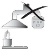
- Do not install above a cooker with a high level grill.
- Do not leave frying pans unattended during use because overheated fats or oils might catch fire.
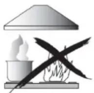
● Never leave naked flames under the cooker hood.
- If the cooker hood is damaged, do not attempt to use.
- Do not flambé under the cooker hood.
● CAUTION: Accessible parts may become hot when used with cooking appliances.
● The minimum distance between the supporting surface for the cooking vessels on the hob and the lowest part of the cooker hood. (When the cooker hood is located above a gas appliance, this distance shall be at least 65 cm)
● The air must not be discharged into a flue that is used for exhausting fumes from appliances burning gas or other fuels. Range hoods and other cooking fume extractors may adversely affect the safe operation of appliances burning gas or other fuels (including those in other rooms) due to back flow of combustion gases. These gases can potentially result in carbon monoxide poisoning. After installation
of a range hood or other cooking fume extractor, the operation of open flued gas appliances should be tested by a competent person to ensure that back flow of combustion gases does not occur.
Always to do:
● Important! Always switch off the electricity supply at the mains during installation and maintenance such as light bulb replacement.
● The cooker hood must be installed in accordance with the installation instructions and all measurements followed.
● All installation work must be carried out by a competent person or qualified electrician.
● Please dispose of the packing material carefully. Children are vulnerable to it.
● Pay attention to the sharp edges inside the cooker hood especially during installation and cleaning.
● Make sure the ducting has no bends sharper than 90 degrees as this will reduce the efficiency of the cooker hood.
● Warning: Failure to install the screws or fixing device in accordance with these instructions may result in electrical hazards.
● Warning: Before obtaining access to terminals, all supply circuits must be disconnected.
Always to do:
● Always put lids on pots and pans when cooking on a gas cooker.
- When in extraction mode, air in the room is being removed by the cooker hood. Please make sure that proper ventilation measures are being observed. The cooker hood removes odours from room but not steam.
● There shall be adequate ventilation of the room when the cooker hood is used at the same time as appliances burning gas or other fuels.
● Cooker hood is for domestic use only.
- If the supply cord is damaged, it must be replaced by the manufacturer, its service agent or similarly qualified persons in order to avoid a hazard.
● This appliance can be used by children aged from 8 years and above and persons with reduced physical, sensory or mental capabilities or lack of experience and knowledge if they have been given supervision or instruction concerning use of the appliance in a safe way and understand the hazards involved. Children shall not play with the appliance. Cleaning and user maintenance shall not be made by children without supervision.
natural_image
Prohibition sign showing two people crossed out of a diagonal line (no text or symbols)Always to do:
●Caution: The appliance and its accessible parts can become hot during operation. Be careful to avoid touching the heating elements. Children younger than 8 years old should stay away unless they are under permanent supervision.
● There is a fire risk if cleaning is not carried out in accordance with the instructions.
● Regulations concerning the discharge of air have to be fulfilled.
● Clean your appliance periodically by following the method given in the chapter MAINTENANCE.
● For safety reason, please use only the same size of fixing or mounting screw which are recommended in this instruction manual.
● Regarding the details about the method and frequency of cleaning, please refer to maintenance and cleaning section in the instruction manual.
● Cleaning and user maintenance shall not be made by children without supervision.
- When the cooker hood and appliances supplied with energy other than electricity are simultaneously in operation, the negative pressure in the room must not exceed 4 Pa(4 x 10 ^-5 bar).
● WARNING: Danger of fire: do not store items on the cooking surfaces.
●A steam cleaner is not to be used.
● NEVER try to extinguish a fire with water, but switch off the appliance and then cover flame e.g. with a lid or a fire blanket.
INSTALLATION (VENT OUTSIDE)
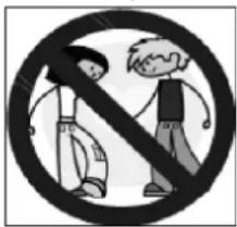
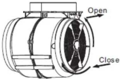
MOUNTING OF THE V-FLAP
If the cooker hood does not have an assembled V-flap 1, you should mount the half-parts to its body. The images only show an example of how to mount the V-flap, because the outlet may vary according to different models and configurations.
To mount the V-flap 1 you should:
- Mount two half-parts 2 into the body 6;
• the pin 3 should be top oriented; - the axis 4 should be inserted into the holes 5 on the body;
- repeat all the operations for the 2nd half-part.
INSTALLATION
If you have an outlet to the outside, your cooker hood can be connected as below picture by means of an extraction duct (enamel, aluminum, flexible pipe or non-flammable material with an interior diameter of 150mm)
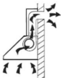
natural_image
Diagram of airflow around a mechanical component with directional arrows indicating movement (no text or symbols)-
Before installation, turn the unit off.
-
The cooker hood should be placed at a distance of 65\~75cm above the cooking surface for best effect. See pic 1.
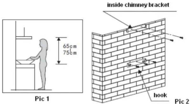
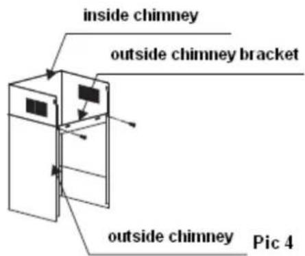
- Install the hook on a suitable place once the installation height is fixed, and keep it in line. The fixed position of the inside chimney bracket is the place of chimney. See pic 2.
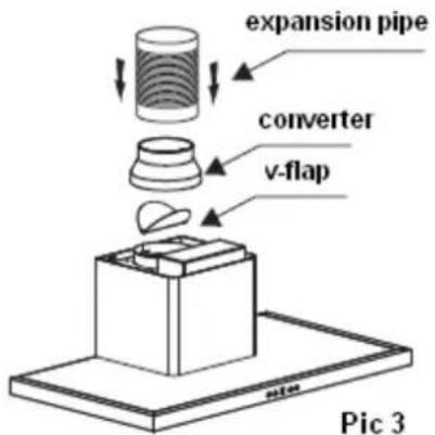
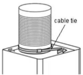
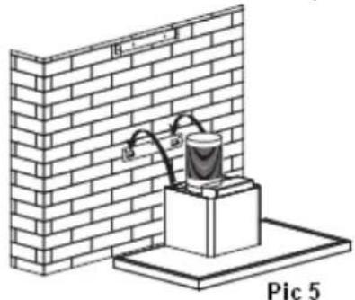
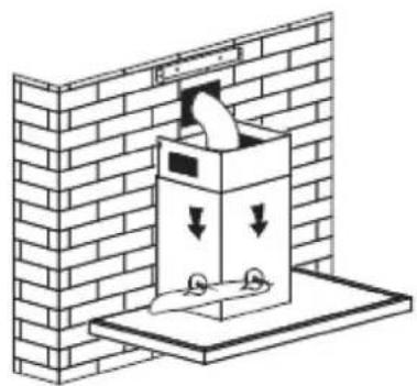
- Intall the v-flap on the outlet. Then attach the converter and expansion pipe, and fix the pipe on the converter with a cable tie, see pic 3. Fix the outside chimney bracket on the outside chimney, and be sure that the inside chimney can be adjusted the height in it freely. Afterwards, install the expansion pipe and chimney on the cooker hood, see pic4. Note: The expansion pipe is not included in the product.
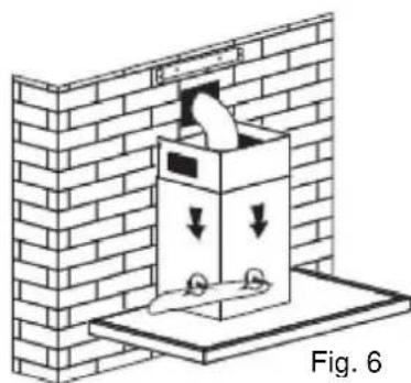
- Put the cooker hood on the hook. Then adjusting the position and fix the body with safety screws. Note: The two safety vents are positioned on the back housing, with diameter of 6mm. See pic 5 & 6.
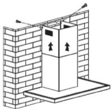
- Adjust the height of the inside chimney to the position of the inside chimney bracket and fix it with screws. See pic 7.
natural_image
Diagram of a brick wall setup with a container and tubing, labeled 'Pic 5' (no text or symbols on the diagram itself)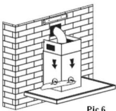
natural_image
Diagram of a brick wall with a box containing a bag, showing airflow or ventilation (no text or symbols)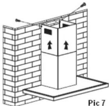
natural_image
Diagram of a brick wall with a vertical structure and directional arrows, labeled 'Pic 7' (no text or symbols on the diagram itself)HINTS FOR EXHAUST DUCT INSTALLATION
The following rules must be strictly followed to obtain optimal air extraction:
- Keep expansion pipe short and straight.
- Do not reduce the size or restrict the expansion pipe.
- When using the expansion pipe always install the pipe pulled taut to minimize pressure loss.
- Failure to observe these basic instructions will reduce the performance and increase noise levels of the cooker hood.
- Any installation work must be carried out by a qualified electrician or competent person.
- Do not connect the ducting system of the hood to any existing ventilation system which is being used for any other appliance, such as warmer tube, gas tube, hot wind tube.
- The angle of the bend of the expansion pipe should not be less than 120^ ; you must direct the pipe horizontally, or, alternatively, the pipe should go up from the initial point and should be led to an outer wall.
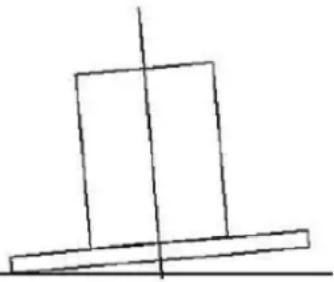
- After the installation, make sure that the cooker hood is level to avoid grease collection at on end.
- Ensure the expansion pipe selected for installation complies with relevant standards and is fire retardant.
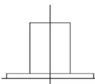
natural_image
Simple geometric diagram with a vertical line intersecting a rectangle (no text or symbols)Right
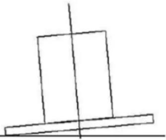
natural_image
Simple line drawing of two stacked rectangles with a vertical line crossing through them (no text or symbols)wrong
Electrical Installation
All installation must be carried out by a competent person or qualified electrician.
Before connecting the mains supply ensure that the mains voltage corresponds to the voltage on the rating plate.
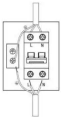
Direct Connection
The appliance must be connected directly to the mains using an omnipolar circuit breaker with a minimum opening of 3mm between the contacts.
The installer must ensure that the correct electrical connection has been made and that it complies with the wiring diagram.
The cable must not be bent or compressed.
Regularly check the power plug and power cord for damage. If the supply cord is damaged, it must be replaced by a special cord or assembly available from the
manufacturer or its service agent.
WARNING: This is a Class I appliance and MUST be earthed
This appliance is supplied with a 3 core mains cable coloured as follows:
Brown = L or Live
Blue = N or Neutral
Green and Yellow = E or Earth
WARNING:
For safety reason, please use only the same size of fixing or mounting screws which are recommended in this instruction manual.
➢ Failure to install the screws or fixing device in accordance with these instructions may result in electrical hazards.
Start Using Your Cooker Hood
Electronic button

[NO TEXT]

[Non-Text]

[Non-Text]

[Non-Text]

[Non-Text]
There are five buttons: (Low), (Mid), (High), (Lamp), (Power). See picture above.
- After connecting to power, indicator light will lit on, all the output close and the hood will enter standby mode. The indicator light will be off automatically after reminding if no operation.
- Power on: Press power button ☉ once, its indicator light will lit on, the hood works at low speed. Indicator light of low speed ⚡ will be bright. Press power button again to close it, and its indicator light will be off. All the function operation of the hood will be closed, the hood enters into standby mode, and run by circle.
The speed buttons and lamp button can work separately and not controlled by the power button. When a certain function button is pressed, the hood operates at that function status. Press (Power) button under any status, the cooker hood will be switched off without any functions.
- Press lamp button ✪ once; lights will be turn on. Indicator light of lamp button
and power button will lit on. Press lamp button again to turn off the lights. Indicator light of lamp button and power button will be off. And recycle like this.
- Press the ⚙️ (High) button once, motor runs on high speed, the indicator light of high button ⚙️ and power button ⏻ will beam. Press high button ⚙️ again and the motor will stop. Indicator light of high button and power button will be off, and run by circle.
- Press the 🎨 (Mid) button once, motor runs on middle speed, the indicator light of middle button 🎨 and power button ⏻ will beam. Press middle button 🎨 again and the motor will stop. Indicator light of middle button and power button will be off, and run by circle.
- Press the 🔗 (low) button once, motor runs on low speed, the indicator light of low button 🔗 and power button ⏻ will beam. Press low button 🔗 again and the motor will stop. Indicator light of low button and power button will be off, and run by circle.
- Low speed, mid speed and high speed cannot work at the same time. When hood is on high speed, press low speed, it will turn to low speed at once; when it is in low speed, press middle speed, it will turn to middle speed immediately, and so on.
TROUBLESHOOTING
| Fault | Possible Cause | Solution |
| Light on, but motor does not work | Fan switch turned off | Select a fan switch position. |
| Fan switch failed | Contact service center. | |
| Motor failed | Contact service center. | |
| Light does not work, motor does not work | House fuses blown | Reset/Replace fuses. |
| Mains power cable is loose or disconnected | Refit mains power cable to power outlet.Switch power outlet on. | |
| Oil leakage | One way valve and the outlet are not tightly sealed | Take down the one way valve and seal with sealant. |
| Leakage from the connection of chimney and cover | Take chimney down and seal. | |
| Lights not working | Broken or faulty bulbs | Replace bulbs as per this instruction. |
| Insufficient suction | The distance between the cooker hood and the gas top is too far | Refit the cooker hood to the correct distance. |
| The Cooker hood inclines | The fixing screw is not tight enough | Tighten the hanging screw and make it horizontal. |
NOTE:

Any electrical repairs to this appliance must conform to your local, state and federal laws. Please contact the service centre if in any doubt before
undertaking any of the above. Always disconnect the unit from the power source when opening the unit.
MAINTENANCE AND CLEANING
Caution:
- Before maintenance or cleaning is carried out, the cooker hood should be disconnected from the mains power supply. Ensure that the cooker hood is switched off at the wall socket.
- External surfaces are susceptible to scratches and abrasions, so follow the cleaning instructions to ensure the best possible result is achieved without damage.
GENERAL
Cleaning and maintenance should be carried out with the appliance cold especially when cleaning. Avoid leaving alkaline or acid substances (lemon juice, vinegar etc.) on the surfaces.
STAINLESS STEEL
The stainless steel must be cleaned regularly (e.g. weekly) to ensure a long life expectancy. Dry with a clean soft cloth. A specialized stainless steel cleaning fluid may be used.
NOTE:
Ensure that wiping is done along with the grain of the stainless steel to prevent any unsightly crisscross scratching patterns from appearing.
CONTROL PANEL SURFACE
The inlay control panel can be cleaned using warm soapy water. Ensure the cloth is clean and well wrung before cleaning. Use a dry soft cloth to remove any excess moisture left after cleaning.
Important
Using neutral detergents and avoid using harsh cleaning chemicals, strong household detergents or products containing abrasives, as this will affect the appearance of the appliance appearance and potentially remove any printing of artwork on the control panel and will void manufactures warrantee.
GREASE MESH FILTERS
The mesh filters can be cleaned by hand. Soak them for about 3 minutes in water with a midl detergent and then brush it gently with a soft brush. Please do not apply too much pressure, avoid to damage it. (Leave to dry naturally out of direct sun light)
Filters should be washed separately to crockery and kitchen utensils. it is advisable not to use rinse aid.
INSTALLING GREASE MESH FILTERS
• To install filters for the following four steps:
- Angle the filter into the slots at the back of the hood.
- Push the button on the handle of the filter.
- Release the handle once the filter fits into a resting position.
- Repeat to install all filters.
CARBON FILTER
Activated carbon filter can be used to trap odors. Normally the activated carbon filter should be changed every 3 to 6 months according to your cooking habits. The installation procedure of the activated carbon filter is as below:
- Before installing or replacing the carbon filters, disconnect the mains power to the unit.
- Press the filter lock and remove the mesh filter.
- Turn the carbon filter on both sides of the motor anti-clockwise. Replace the carbon filters with the new carbon filters.
- Replace the mesh filter.
- Connect the mains power supply to the wall socket.
NOTE:
- Make sure the filter is securely locked. Otherwise, it would loosen and cause danger.
- When activated carbon filter attached, the suction power will be lowered.
BULB REPLACEMENT
Important :

The bulb must be replaced by the manufacturer, its service agent or similarly qualified persons.
Always switch off the electricity supply before carrying out any operations on the appliance. When handling bulb, make sure it has completely cooled down before any direct contact with hands.
When handling bulbs hold with a cloth or gloves to ensure perspiration does not come in contact with the bulb as this can reduce the life of the bulb.
Note:
- Before replacing light that the cooker hood can be isolated from the supply mains by means of a plug or an all-pole switch.
- Protect against danger when changing lights, such as wearing gloves.
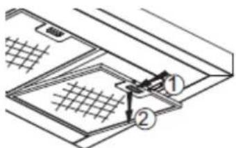
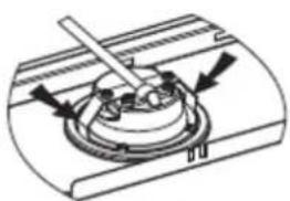
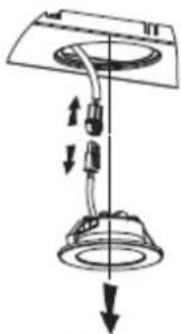
Changing the lights:
Remove the grease filter.
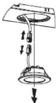
Use a tool or the hand to press the spring splinter of both sides of LED light to the inside, until the light is pressed out, see pic 1. Then slightly pull the light connecting wire out, and dismantle the terminal of the light connecting wire. See pic 2.
Apply the reverse procedure to install the light back.
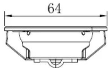
• ILCOS D code for this lamp is: DSR-1.5/65-S-64
- LED modules -round lamp
- Max wattage: 2 × 1.5 ~W
- Voltage range: DC 12V
- Dimensions:
natural_image
Mechanical assembly diagram showing a rotating component with arrows indicating motion direction (no text or symbols)Pic 1
natural_image
Diagram of a ceiling lamp with hanging components and directional arrows indicating motion (no text or symbols)Pic 2
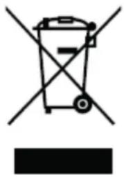
ENVIRONMENTAL PROTECTION:
natural_image
Symbol of a trash bin crossed with a diagonal line and a horizontal bar below (no text or labels)This product is marked with the symbol on the selective sorting of waste electronic equipment. This means that this product must not be disposed of with household waste but must be supported by a system of selective collection in accordance with Directive 2012/19/EU. It will then be recycled or dismantled to minimize impacts on the environment, electrical and electronic products are potentially dangerous for the environment and human health due to the presence of hazardous substances. For more information, please contact your local or regional authorities.
NOTE:
The following shows how to reduce total environmental impact (e.g. energy use) of the cooking process).
(1) Install the cooker hood in a proper place where there is efficient ventilation.
(2) Clean the cooker hood regularly so as not to block the airway.
(3) Remember to switch off the cooker hood light after cooking.
(4) Remember to switch off the cooker hood after cooking.
INFORMATION FOR DISMANTLING
Do not dismantle the appliance in a way which is not shown in the user manual. The appliance could not be dismantled by user. At the end of life, the appliance should not be disposed of with household waste. Check with your Local Authority or retainer for recycling advice.
Sommaire
natural_image
Illustration of a laboratory setup with a lamp, heating element, and control panel (no text or symbols)INSTALLATION (EVACUATION EXTERNE)
MONTAGE DU RABAT EN V
INSTALLATION
natural_image
Diagram of airflow around a mechanical component with directional arrows indicating movement (no text or symbols)natural_image
Diagram of a brick wall with a paper feeding into a container, showing airflow direction (no text or symbols)Figure 5
natural_image
Illustration of a box with downward arrows inside, mounted on a platform against a brick wall background (no text or symbols)Figure 6
natural_image
Isometric line drawing of a brick wall with a central box and two upward arrows, no text or symbols present.Figure 7
CONSEILS POUR L'INSTALLATION DU CONDUIT D'ÉVACUATION
natural_image
Six circular icons with corresponding symbols: a leaf, fan, sun, and power button (no text or labels)INSTALLATION DES FILTRES À GRAISSE EN CAISSETTES MÉTALLIQUES
REEMPLACEMENT D'UN LAMPE
Important :

natural_image
Diagram of a ceiling lamp with adjustable arm and base, showing no text or symbolsFigure 2
PROTECTION ENVIRONNEMENTALE
natural_image
Symbol of a trash bin crossed with a diagonal line, no text or numbers presentnatural_image
Illustration of a lamp illuminating a heating lamp with a crossed-out device (no text or symbols)INSTALAÇÃO
natural_image
Diagram of airflow around a mechanical component with directional arrows indicating movement (no text or symbols)natural_image
Diagram of a scientific apparatus with a brick wall and connected components, no visible text or symbolsFig. 5
natural_image
Diagram of a brick wall-mounted device with downward arrows indicating flow or movement, labeled as Fig. 6 (no text or symbols on the device itself)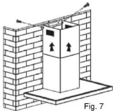
natural_image
Diagram of a brick wall with a vertical structure and upward arrows, labeled Fig. 7 (no text or symbols on the diagram itself)INSTALAR OS FILTROS DE REDE DE GORDURA
natural_image
Mechanical component diagram showing a lever and base with arrows indicating direction (no text or symbols)Fig. 1
natural_image
Diagram of a ceiling lamp with adjustable arm and load arrows (no text or symbols)Espaço 2
natural_image
Symbol of a trash bin with crossed lines indicating no waste or restriction, and a solid black rectangle below (no text or labels)INSTALACIÓN
natural_image
Diagram of a mechanical or fluidic system with directional arrows indicating flow or movement (no text or symbols)natural_image
Diagram of a gas collection apparatus mounted on a brick wall, labeled Fig 5 (no text or symbols on the diagram itself)
natural_image
Diagram of a box with downward arrows inside, mounted on a base against a brick wall (no text or symbols)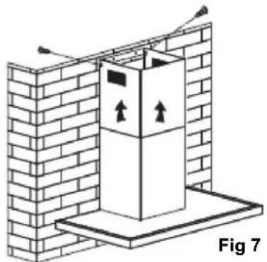
natural_image
Diagram of a brick wall with a vertical structure and upward arrows, labeled Fig 7 (no text or symbols on the diagram itself)natural_image
Simple geometric diagram with a vertical line intersecting a rectangle (no text or symbols)Correcto
natural_image
Simple line drawing of two stacked rectangles with a vertical line intersecting them (no text or symbols)Incorrecto
natural_image
Mechanical component diagram showing a lever and base with arrows indicating direction (no text or symbols)Fig 1

natural_image
Diagram of a ceiling lamp with hanging components and directional arrows indicating motion (no text or symbols)Fig 2