LZ7500 - Screen KENWOOD - Free user manual and instructions
Find the device manual for free LZ7500 KENWOOD in PDF.

Frequently Asked Questions - LZ7500 KENWOOD
User questions about LZ7500 KENWOOD
0 question about this device. Answer the ones you know or ask your own.
Ask a new question about this device
Download the instructions for your Screen in PDF format for free! Find your manual LZ7500 - KENWOOD and take your electronic device back in hand. On this page are published all the documents necessary for the use of your device. LZ7500 by KENWOOD.
USER MANUAL LZ7500 KENWOOD
- Contents
- Safety Precaution
Operation 3
Basic Operation 3
Power
- Switching the Monitor's Picture
Volume - Switching the Video Screen Mode
- Switching the Speaker Mode
Screen Control Screen. 4
Adjusting the Picture Quality
Setup Menu Screen 4
- Select the Setup Menu Screen
- Select the System Setup Screen
- Select the Touch Panel Adjustment Screen
- Exit the Setup Menu Screen
System Setup Screen-1 5
- Setting the Navigation Mode
- Setting the AV IN-1 Mode
-
Setting the AV IN-2 Mode
-
Setting the Camera Mode
- Switching to the System Setup Screen -2
- Exit the System Setup Screen
System Setup Screen-2 6
- Setting the AV Output Mode
- Touch Sensor Tone
- Return to the System Setup Screen -1
- Exit the System Setup Screen
Touch Panel Adjustment Screen 6
- Touch Panel Adjustment
On Screen Control Mode. 7
- Switching the Monitor's Picture [VS]
- Switching the Video Screen Mode [WD]
- Switching the Speaker Mode [SP]
- Setting the AV Output Mode [AV]
- Exit the On Screen Mode
Installation. 8
Troubleshooting Guide 12
Specifications 12
Safety Precaution
▲WARNING
To prevent injury and/or fire, take the following precautions:
- Ensure that the unit is securely installed. Otherwise it may fly out of place during collisions and other jolts.
- When extending the ignition or ground cables, make sure to use automotive-grade cables or other cables with an area of 0.75mm^2 (AWG18) or more to prevent wire deterioration and damage to the wire coating.
- To prevent short circuits, never put or leave any metallic objects (e.g., coins or metal tools) inside the unit.
If the unit starts to emit smoke or strange smells, turn off the power immediately and consult your Kenwood dealer - Do not touch the liquid crystal fluid if the LCD is damaged or broken due to shock. The liquid crystal fluid may be dangerous to your health or even fatal.
If the liquid crystal fluid from the LCD contacts your body or clothing, wash it off with soap immediately.
CAUTION
To prevent damage to the machine, take the following precautions:
- Make sure to ground the unit to a negative 12V DC power supply.
- Do not open the covers of the unit.
- Do not install the unit in a spot exposed to direct sunlight or excessive heat or humidity. Also avoid places with too much dust or the possibility of water splashing.
- Do not subject the monitor unit to excessive shock, as it is a piece of precision equipment.
- When replacing a fuse, only use a new one with the prescribed rating. Using a fuse with the wrong rating may cause your unit to malfunction.
- To prevent short circuits when replacing a fuse, first disconnect the wiring harness.
- Do not use any screws except for the ones provided. The use of improper screws might result in damage to the main unit.
- You cannot view video pictures whilst the vehicle is moving. To enjoy video pictures, find a safe place to park and engage the parking brake.
NOTE
If you experience problems during installation, consult your Kenwood dealer.
The illustrations of the display and the panel appearing in this manual are examples used to explain more clearly how the controls are used. Therefore, what appears on the display in the illustrations may differ from what appears on the display on the actual equipment, and some of the illustrations on the display may represent something impossible in actual operation.
2 - English
Basic Operation
Screen Mode
NORMAL
FULL
- JUST
ZOOM
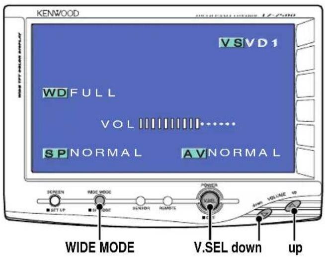
Power
Turning on the power
Press the [V.SEL] button.
Turning off the power (Stand by mode)
Press the [V.SEL] button for at least 1 second.
Switching the Monitor's Picture
Press the [V.SEL] button.
Each time the button is pressed the monitor's picture switches as follows:
Display Picture
"NAV" Navigation (During "NAV" set to "RGB" or "AV IN1")
"VD1" Video 1 (During "VD1" set to "AV-IN1")
"VD2" Video 2 (During "VD2" set to "AV-1N2")
"CAM" Video 3 (During "CAMERA/VIDEO" set to "VD")

For "NAV", "VD" and "CAMERAVIDEO" setting, refer to

You cannot view video pictures whilst the vehicle is moving. To enjoy video pictures, find a safe place to park and engage the parking brake.
Volume
Increasing Volume:
Press the [up] button.
Decreasing Volume:
Press the [down] button.
Switching the Video Screen Mode
Press the [WIDE MODE] button.
Each time the button is pressed the screen mode switches as follows:
Display Setting
"FULL" Full screen mode
"ZOOM" Zoom screen mode
"JUST" Just screen mode
"NORMAL" Normal screen mode

You cannot operate when the navigation picture is displayed.
Switching the Speaker Mode
Press the [WIDE MODE] button for at least 1 second.
Each time the button is pressed for at least 1 second the built-in speaker mode switches as follows:
Display Setting
"NORMAL" Sound with monitor picture
"NAV" Sound with navigation picture
"VIDEO1" Sound with video 1 picture
"VIDEO2" Sound with video 2 picture
"OFF" Built-in speaker is turned off
Screen Control Screen
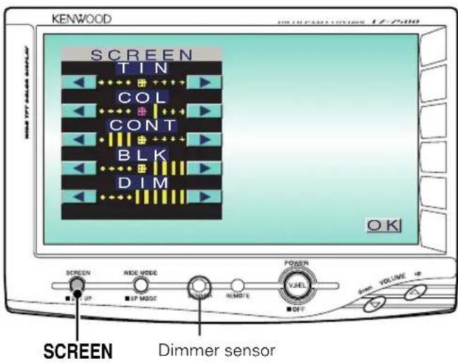
Adjusting the Picture Quality
1 Displaying the Screen Control Screen Press the [SCREEN] button.
2 Setting Touch the [or] button.
Item Touch Setting
| TIN [▲] Stronger green level [▲] Stronger red level |
| COL [▲] Deeper colour [▲] Paler colour |
| CONT [▲] Stronger contrast [▲] Less contrast |
| BLK [▲] Less black level [▲] Stronger black level |
| DIM [▲] Brighter screen [▲] Darker screen |
The [TIN] and [COL] cannot be adjusted for the RGB- navigation picture or the setup screen.
The [TIN] cannot be adjusted for the picture of PAL.
- Separate picture quality settings can be stored for the video and navigation screens.
As regards [DIM] (Dimmer) adjustment: There is no connection with the vehicle's illumination switch. (A dimmer sensor is installed facing the front of monitor unit for light detection).
3 Exit the Screen Control Screen
Touch the [OK] button.
If you make no operation for 10 seconds, the screen control screen is automatically canceled.
Setup Menu Screen
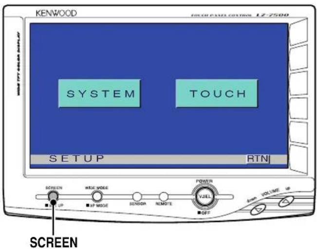
Select the Setup Menu Screen
Press the [SCREEN] button for at least 1 second. Setup Menu Screen is displayed.
Select the System Setup Screen
Touch the [SYSTEM] button. System Setup Screen is displayed.(Page 5)
Select the Touch Panel Adjustment Screen
Touch the [TOUCH] button. Touch Panel Adjust Screen is displayed.(Page 6)
Exit the Setup Menu Screen
Touch the [RTN] button.
If you cannot selected a setup menu item. Press the [SCREEN] button for at least 2 second, the touch panel position settings are reset to the factory defaults.
System Setup Screen-1

Setting the Navigation Mode
Touch Setting
[RGB] It becomes the RGB-image mode setting. Operate the V.SEL button when the RGBimage from the navigation unit connected to
Setting the AV IN-1 Mode
Touch Setting
[AV-IN1] It becomes the video mode setting. Operate the V.SEL button when the image from the device connected to
[OFF] It becomes the OFF mode setting. Use this setting when there's nothing connected to the

If you select "AV-IN 1", "NAV" setting is changed to "RGB".
Setting the AV IN-2 Mode
Touch Setting
[AV-IN2] It becomes the video mode setting. Operate the V.SEL button when the image from the device connected to
[OFF] It becomes the off mode setting.Use this setting when there's nothing connected to the < AV IN-2> terminal.
Setting the Camera Mode
Touch Setting
[■AUTO] It becomes the Rear view camera mode setting. When the reverse sensor cable is powered up, the monitor image is switched to the image of the device connected to the
[VD] It becomes the video mode setting. Operate the V.SEL button when the image from the device connected to
OFF] It becomes the off mode setting.Use this setting when there's nothing connected to the
Switching to the System Setup Screen -2
Touch the [▶] button.
Exit the System Setup Screen
Touch the [RTN] button.
Return to the setup menu screen.
System Setup Screen-2
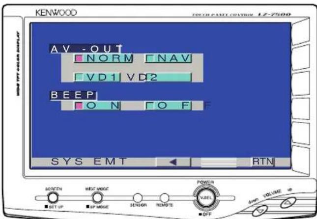
Setting the AV Output Mode
Touch Setting
[NORMAL] Picture/sound with monitor picture
[NAV] Navigation Sound
[VD1] Picture/sound from
[VD2] Picture/sound from
Touch Sensor Tone
Setting the operation check sound (beep sound) ON/OFF.
Touch Setting
[ON] Touch sensor tone is turned on
OFF] Touch sensor tone is turned off
Return to the System Setup Screen -1
Touch the [ ] button.
Exit the System Setup Screen
Touch the [RTN] button.
Return to the setup menu screen.
Touch Panel Adjustment Screen
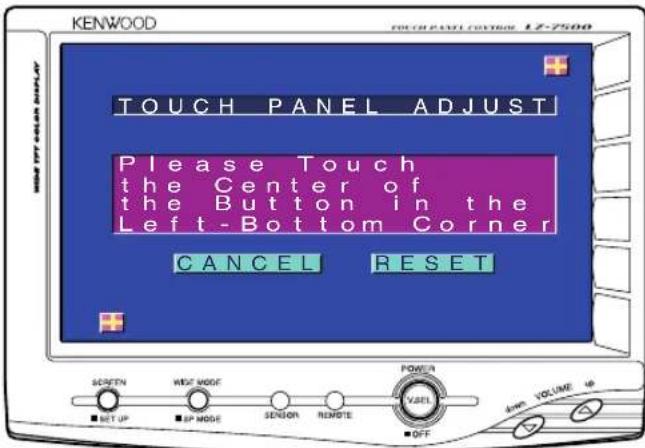
Touch Panel Adjustment
The touch panel can be adjusted if the position touched and the operation performed do not match.
1 Accurately touch the mark at the lower left.
2 Accurately touch the mark at the upper right.
When the mark at the upper right is touched, the adjustment is completed and the system setup menu screen reappears.

- If the [CANCEL] button is touched without touching the button at the lower left, the adjustment is cancelled and the screen that was set before switching to the system setup menu reappears.
- If the [ CANCEL ] button is touched after touching the button at the lower left, the button at the lower left reappears.
- If the [RESET] button is touched, the settings are reset to the factory defaults and the setup menu screen reappears.
On Screen Control Mode
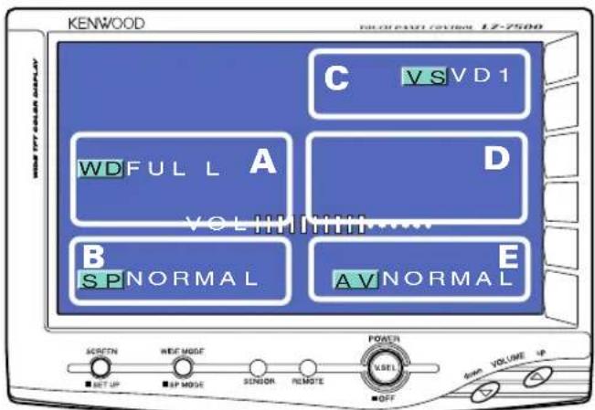
When the current setting information is displayed on the screen, touching a dotted line will enable operation of each of the following items:
Switching the Monitor's Picture [VS]
Touch the C part.
Each time the C part is touched the monitor's picture switches as follows:
Display Picture
"NAV" Navigation (During "NAV" set to "RGB" or "AV IN1")
"VD1" Video 1 (During "VD1" set to "AV-IN1")
"VD2" Video 2 (During "VD2" set to "AV-IN2")
"CAM" Video 3 (During "CAMERAVIDEO" set to "VD")

For "NAV", "VD" and "CAMERAVIDEO" setting, refer to

You cannot view video pictures whilst the vehicle is moving. To enjoy video pictures, find a safe place to park and engage the parking brake.
Switching the Video Screen Mode [WD]
Touch the A part.
Each time the A part is touched the screen mode switches as follows:
Display Setting
"FULL" Full screen mode
"ZOOM" Zoom screen mode
"JUST" Just screen mode
"NORMAL" Normal screen mode

You cannot operate when the navigation picture is displayed.
Switching the Speaker Mode [SP]
Touch the B part.
Each time the B part is touched the built-in speaker mode switches as follows:
Display Setting
"NORMAL" Sound with monitor picture
"NAV" Sound with navigation picture
"VIDEO1" Sound with video1 picture
"VIDEO2" Sound with video2 picture
"OFF" Switch off the built-in speakers
Setting the AV Output Mode [AV]
Touch the E part.
Each time the E part is touched the AV output mode switches as follows:
Display Setting
"NORMAL" Picture/sound with monitor picture
"NAV" Navigation Sound
"VIDEO1" Picture/sound from
"VIDEO2" Picture/sound from
Exit the On Screen Mode
Touch the D part.

If you make no operation for 10 seconds, the On screen control mode is automatically canceled.
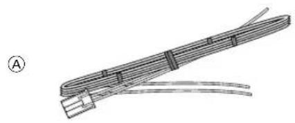
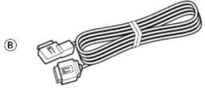
Accessories

G
E


H
(04× 12mm)
C

F

①
(04x16mm)
The use of any accessories except for those provided might result in damage to the unit. Make sure only to use the accessories shipped with the unit, as shown above.
Installation Procedure
1 To prevent short circuits, remove the key from the ignition and disconnect the terminal of the battery.
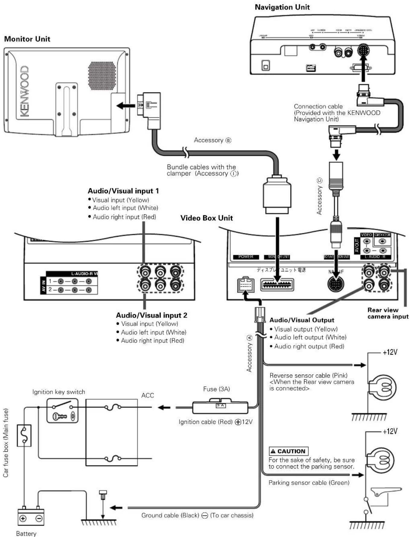
2 Make the proper input and output cable connections for each unit.
3 Connect the wiring harness cables in the following order: ground, ignition.
4 Connect the wiring harness connector to the unit.
5 Install the unit in your car.
6 Reconnect the terminal of the battery.
WARNING
- This product is intended for use with 12V DC negative ground power only. Do not connect it to any other power supply
- To prevent shorting, disconnect the battery cable from the negative terminal of the battery during installation.
- Be sure to firmly stabilise this product. Do not install it in a location which is not stable.
- Follow the installation and wiring procedures described in this manual. Improper wiring or modified installation can not only result in malfunction or damage to the unit but may also result in an accident.
-
Do not install the unit in the following locations.
-
A location which interferes with the operation of the air bag system.
A location which is not made of plastic.
Installing on leather, wood or cloth may damage the surface.
- A location subject to direct sunlight, subject to the air from the air conditioner, or subject to moisture or high temperature.
This may cause deformation of the monitor unit.
- Be sure to use the supplied screws for installation. Using screws longer than those supplied may destroy parts inside the unit causing it to smoke. Using screws shorter than those supplied may cause the unit to come looks from the installation bracket.
- If you are not going to install the unit using the supplied monitor stand, be sure to use a commercially available monitor stand. (Mounting holes for such a stand are located on the bottom of the monitor unit.)
CAUTION
If your car's ignition does not come with an ACC position, connect the ignition cables to a power source that can be turned on and off with the ignition key. If you connect the ignition wire to a power source that receives a constant voltage supply, as with battery cables, the battery may die.
- If the fuse blows, first make sure that the cables have not caused a short circuit, then replace the old fuse with one with the same rating.
- Do not let unconnected cables or terminals touch metal on the car or anything else conducting electricity. To prevent short circuits do not remove the caps from unused terminals or from the ends of the unconnected cables.
- After the unit is installed, check whether the brake lamps, blinkers, wipers, etc. on the car are working properly.
- Insulate unconnected cables with vinyl tape or other similar material.
- Thoroughly wipe away oil and other dirt from the installation surface. Please avoid installation on uneven surfaces.
Connection
Installation for Monitor Unit
Installation location and cleaning
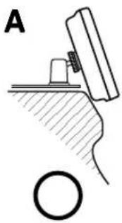
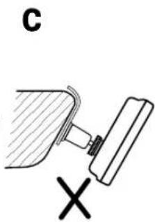
Select for installation a location where the stand can be placed completely horizontal or where the front edge of the support (petal-shaped part) can be attached horizontally as shown in Figure A.
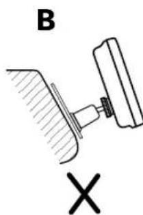
Do not install in locations where the entire support is at a diagonal such as in Figure B or where the monitor unit is facing down such as in Figure C.
CAUTION
Thoroughly wipe away and dust or grease from the installation location using a cloth which has been soaked in a neutral cleaning agent and wrung out. Attach the stand after allowing the installation location to dry.
1 Bend the stand support to conform to the shape of the installation location.
2 Adjust the shape of the support so that there is no rattling or gap when the stand is placed on the support.
3 Peel off the protective strip from the double-sided tape on the bottom of the stand and securely attach the stand.
CAUTION
- Do not attach the double-sided tape more than once or touch the adhesive with your fingers as this will weaken its adhesive strength.
- If the temperature of the surface of the installation location is low, warm it up using a heater or other means before attaching the stand. Low temperature may weaken the adhesive strength of the tape.
The supplied stand is specially intended for this product. Do not use it with another monitor.
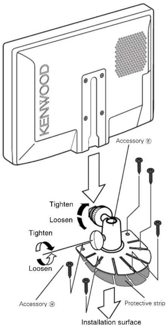
4 Secure the stand using the supplied tapping screw (Accessory H).
5 After attaching the stand, allow it to sit undisturbed for 24 hours.
6 Take care not to apply any force to the stand during this time.
7 Fully loosen the installation screws, align the slit on the rear of the unit with the installation shoe and slide the monitor unit onto the stand.
8 Adjust the height, horizontal angle and vertical angle of the monitor and securely tighten the installation screws.
You can also adjust the monitor unit's forward position by loosening the angle adjustment knobs and adjusting the angle of the monitor unit's installation stand.
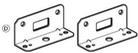
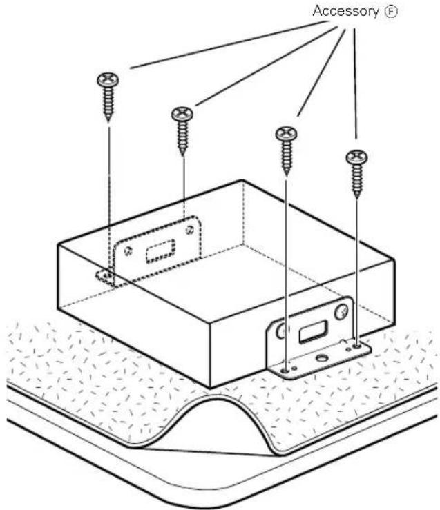
Installation for Video Box Unit
Securing to audio board
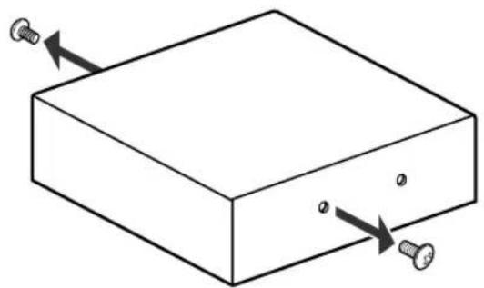
1 Remove the screws on both sides that are already attached to Video Box Unit.
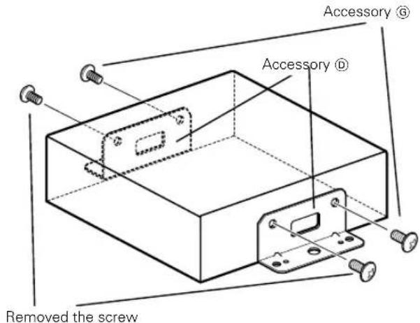
2 Use the screws removed in step 1 and attached screws (Accessory) to fix the bracket (Accessory) onto both sides of Video Box Unit.
3 Use screws (Accessory F) to fix Video Box Unit onto an audio board or another.
What might appear to be a malfunction in your unit may just be the result of slight misoperation or miswiring. Before calling service, first check the following table for possible problems.
SOLUTIONPOSSIBLE CAUSEPROBL
| The power does not turn on. The fuse has blown. After checking for short circuits in the cables, replace the fuse with one having the same rating. | |
| No ACC position on vehicle ignition. | Connect the same cable to the ignition as the battery cable. |
| No video picture appears. The unit is not connected to the parking brake detection switch. | Make proper connections according to "Connection". |
| The parking brake is not engaged. | For safety reasons no video picture are displayed while the vehicle is moving. Engaging the parking brake will cause picture to be displayed. |
| The screen is dark. The unit is in a location where temperature is low. | If the temperature of the monitor unit drops, the screen may appear darker when power is first turned on due to the characteristics of a liquid crystal panel. Wait a while after turning power on for the temperature to rise. Normal brightness will return. |
Specifications
Specifications subject to change without notice.
Monitor Unit
Screen size 6.95 inches wide
154.1(W) × 86.6(H) × 176.7(Diagonal) mm
6-1/16(W) x 3-7/16(H) inches
Display system. Transparent TN LCD panel
Drive system TFT active matrix system
Number of pixels. 336,960 pixels (480 H x 234 V x RGB)
Effective pixels 99.99%
Pixel arrangement RGB striped arrangement
Back lighting Cold cathode tube
Speaker power 1 W (40 0 x 1)
Video Box Unit
Colour system NTSC/PAL
External video input level (RCA jacks) 1± 0.1 Vp-p/75Ω
External audio input level (RCA jacks) 1 V/22 KΩ
Video output level (RCA jacks) 1 ± 0.1 Vp-p/ 75 Ω
Audio output level (RCA jacks) . 500 mV/ 1 KΩ
Analog RGB input 0.7 Vp-p/ 75 Ω
General
Operating voltage 14.4 V DC (11 - 16 V)
Consumed Power 14 W
Operational temperature range -10°C to +60°C
Storage temperature range -30°C to +80°C
Size
(Monitor unit) 189(W) x 131(H) x 37(D) mm
7-7/16(W) x 5-3/16(H) x 1-7/16(D) inches
(Video box unit) 167(W) x 38(H) x 152(D) mm
6-9/16(W) x 1-1/2(H) x 6(D) inches
Mass
(Monitor unit) 580 g(1.28 LBS)
(Video box unit) 620 g(1.37 LBS)
Although the effective pixels for the liquid crystal panel is given as 99.99% or more, 0.01% of pixels may not light or may light incorrectly.
KENWOOD
Table des matieres
SOLUTIONCAUSE POSSIBLEPROBL
"NAV" Navigationston