
SIG7900 - Electronic module FRACARRO - Free user manual and instructions
Find the device manual for free SIG7900 FRACARRO in PDF.
| Brand | Fracarro |
| Model | SIG7900 |
| Product type | Electronic module for Headline system (headend) |
| Main functions | Power distribution to modules, BUS communication, network programming |
| Power supply | 220-240 V~, 50-60 Hz |
| Power consumption | 2 W (module alone), 100 W max (complete system) |
| Operating temperature | -5 to +45 °C |
| Dimensions (19" rack) | Width 482.6 mm, depth 250 mm, height 1U (44.45 mm) per module |
| Estimated weight | Approximately 2 kg per module (complete rack depending on configuration) |
| Mounting | In a 19" rack cabinet with supplied screws |
| Connectivity | RJ45 ports (IN/OUT) for serial BUS communication |
| Module identification | Numbered labels 1 to 11 for position in the row |
| Programming | Via TPE programmer connected to RJ45IN |
| Maximum number of rows | 15 rows |
| Maximum modules per row | 11 modules + 1 interconnection module |
| Electrical safety | Grounding mandatory, installation by qualified personnel |
| Do not open | Risk of electric shock, warranty void |
| Maintenance and cleaning | Disconnect before intervention, use a dry cloth, do not block ventilation |
| Spare parts and repairability | Interventions reserved for qualified technician, use of original parts |
| Included accessories | Power cord, adhesive labels, extraction handles |
| Warranty | Warranty valid only if installed by professional |
Frequently Asked Questions - SIG7900 FRACARRO
User questions about SIG7900 FRACARRO
0 question about this device. Answer the ones you know or ask your own.
Ask a new question about this device
Download the instructions for your Electronic module in PDF format for free! Find your manual SIG7900 - FRACARRO and take your electronic device back in hand. On this page are published all the documents necessary for the use of your device. SIG7900 by FRACARRO.
USER MANUAL SIG7900 FRACARRO
ISTRUZIONI PER L'USO
OPERATING INSTRUCTIONS
INSTRUCTIONS D'EMPLOI
INSTRUCCIONES DE USO
natural_image
Person operating a FRACARRO industrial control unit with multiple vials (no visible text or symbols)natural_image
Interior view of an electrical enclosure labeled 'FRACARRO' with hands operating it (no readable text beyond label)natural_image
Black-and-white photo of a FRACARRO electrical enclosure with open panel and hands installing components (no visible text or symbols)Fig. 4
natural_image
Interior view of a FRACARRO industrial control cabinet with open doors and internal modules (no visible text or symbols)FRACARRO
Fig. 5
natural_image
Interior view of an electronic device showing internal circuitry and connectors (no visible text or symbols)natural_image
Close-up of an electronic control panel with a digital display and cable, no visible text or symbolsFig. 7
natural_image
Close-up of hands installing a cable with a connector on an open server rack (no visible text or symbols)natural_image
Close-up of hands installing or adjusting a server rack with an open circuit board (no visible text or symbols)natural_image
Close-up of a hand inserting a component into an open electronic device chassis (no visible text or symbols)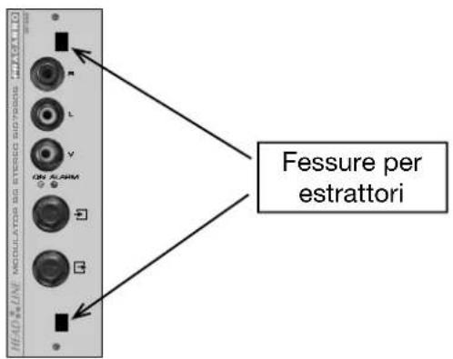
natural_image
Close-up of a hand inserting a component into an electronic device panel (no visible text or symbols)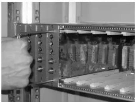
natural_image
Close-up of a hand inserting a component into a server rack (no visible text or symbols)
natural_image
Close-up of a hand inserting a component into a server rack (no visible text or symbols)The unit should be installed by authorised and qualified personnel.
Do not open the module cover as there are high voltage parts. Only use the original power cable supplied.
SELECTING PRODUCT LOCATION:
Install the product in a dry location leaving space around the product housing to allow ventilation. Do not place the equipment above or near radiators, hobs, etc. where it may be exposed to heat or oily vapours.
Excessive temperature and/or heat build-up will adversely affect the life of the product and could cause a hazard.
Moisture may damage the product. If condensation is present, ensure the product is dry before installation. Acclimatise the product in the installation location for two hours before connecting to the mains.
CAUTION! The unit should only be opened by authorised personnel. Any repairs or attempts to repair this equipment will invalidate the guarantee. Remove the mains plug before carrying out any maintenance work on the product.
SAFETY:
This product is categorised as Class II, in accordance with EN60065 and should be connected to the power supply using the cable supplied. Never connect the mains cable to the PME of the mains network. The installation must comply with local safety regulations.
EARTHING:
This product must be connected to the distribution system earth in accordance with EN50083-1 part 10. Do not connect the product to the protected earth of the power supply.
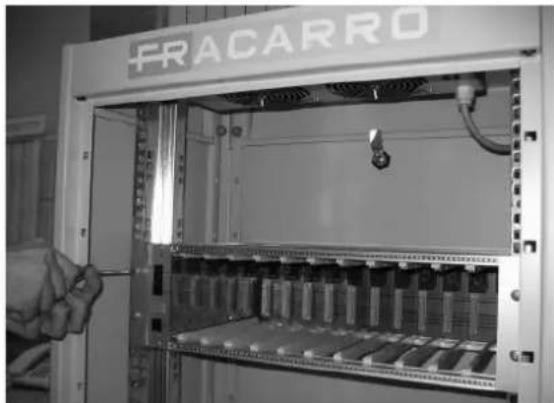
PRODUCT DESCRIPTION
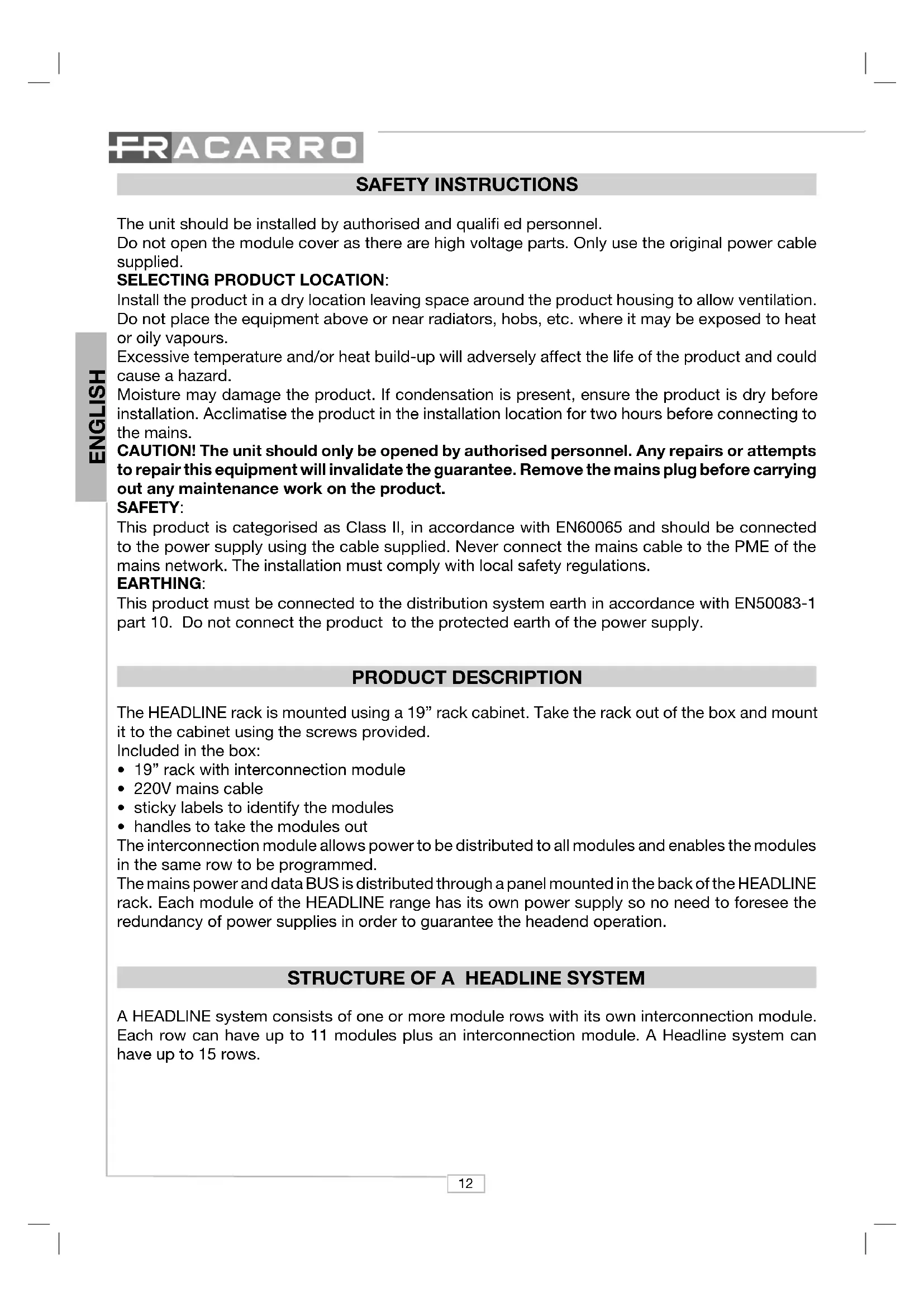
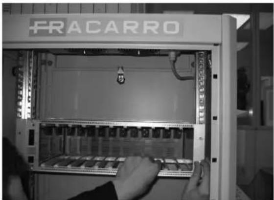
The HEADLINE rack is mounted using a 19" rack cabinet. Take the rack out of the box and mount it to the cabinet using the screws provided.
Included in the box:
- 19" rack with interconnection module
• 220V mains cable - sticky labels to identify the modules
- handles to take the modules out
The interconnection module allows power to be distributed to all modules and enables the modules in the same row to be programmed.
The mains power and data BUS is distributed through a panel mounted in the back of the HEADLINE rack. Each module of the HEADLINE range has its own power supply so no need to foresee the redundancy of power supplies in order to guarantee the headend operation.
STRUCTURE OF A HEADLINE SYSTEM
A HEADLINE system consists of one or more module rows with its own interconnection module. Each row can have up to 11 modules plus an interconnection module. A Headline system can have up to 15 rows.
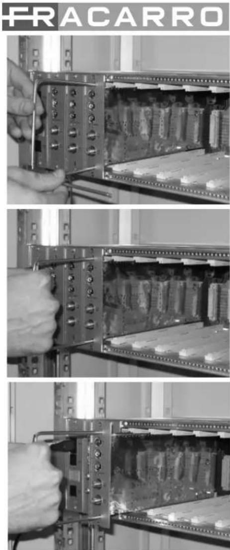
RACK MOUNTING
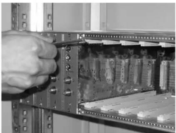
Fig. 1
natural_image
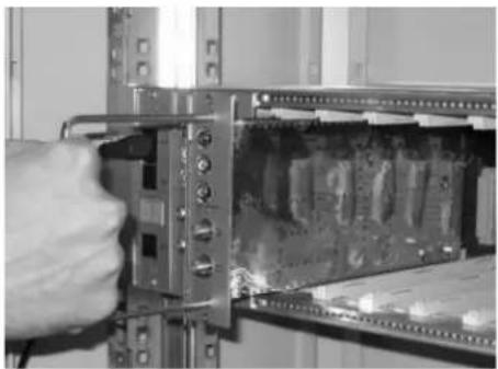
Person operating a FRACARRO industrial control unit with visible internal components (no text or symbols on the device itself)Take the rack out of the box and mount it using a 19" rack cabinet. It is recommended that the rack is held as shown in fig.1 to avoid excess pressure on the guide cards.
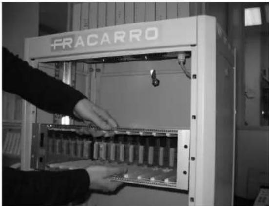
Fig. 2
natural_image
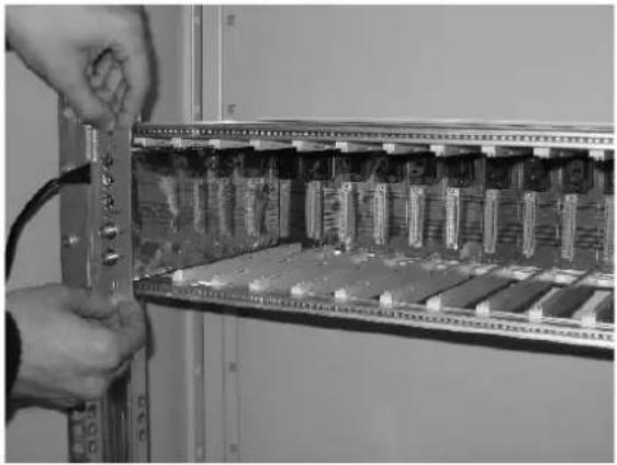
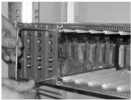
Interior view of an electrical enclosure labeled 'FRACARRO' with hands operating it (no readable text beyond label)Use the screws provided to attach the module to the rack using the holes (see fig. 2, 3 & 4).
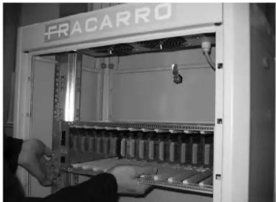
Fig. 3
natural_image
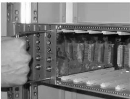
Interior view of an electrical enclosure labeled 'FRACARRO' with open panel and hand inserting components (no readable text beyond label)Fig. 4

natural_image
Interior view of an electrical enclosure labeled 'FRACARRO' with a hand adjusting the panel (no readable text beyond label)FRACARRO
Fig. 5

natural_image
Interior view of an electronic device showing internal circuitry and connectors (no visible text or symbols)Fig. 6
natural_image
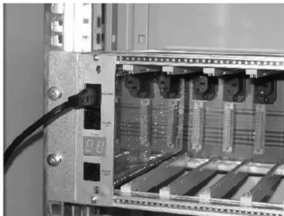
Close-up of an electronic device rack with a black cable inserted, showing internal components and a digital display (no visible text or symbols)Fig. 7

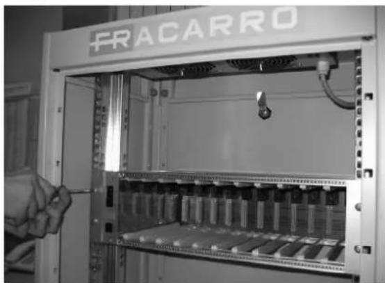
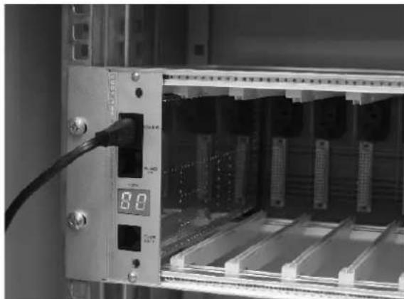
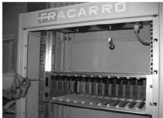
Connect the mains cable supplied in the rack box to the interconnection module (see fig. 5 and 6).
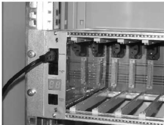
After a few seconds the display will light up and show "00". This means there is no set address on the interconnection module. Connect the TPE to the interconnection module to be programmed using RJ45IN (see fig.7).
The TPE recognises the new module and needs its address. Using the "arrow up" & "arrow down" buttons on the TPE the number assigned can be modified and then push the V button to confirm. It is recommended that the first row of the headend is set as row 1, the second as row 2 and so on up to the 15th.
Important: It is not possible to assign the same number to two or more rows.
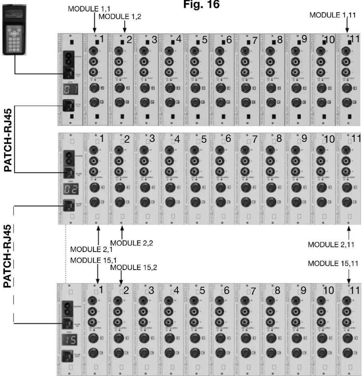
The row is allocated a number so that each module can have an individual address consisting of 2 numbers, the first indicates the row number, the second the position of the module within the row (see fig.15).
Repeat this operation for each mounting rack installed.
INSTALLING MODULES IN EACH ROW
Fig. 8
natural_image
Close-up of hands installing or adjusting a circuit board inside an open server rack (no visible text or symbols)Insert the modules between the guides and push them back carefully until they are in contact with the back panel. When the green LED lights up, the module is installed and powered (see fig. 8).
Fig. 9
natural_image
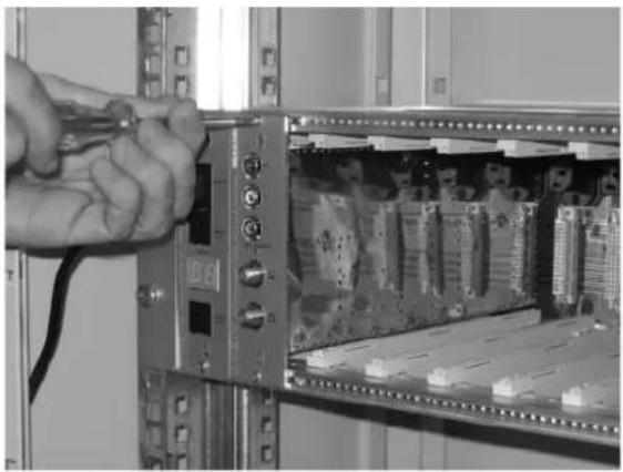
Close-up of hands using a tool to switch an open server rack with visible circuit boards (no text or symbols)After installing the module attach it to the mounting rack using the screws supplied in the accessory bag (see fi g. 9).
Repeat these steps for all modules to be installed.
TAKING THE MODULES OUT
To take the module out of the mounting rack use the 2 handles (extracting tools) included in the rack box.
Take out the screws on the front panel of the module to be removed and insert the handles into the rectangular holes (see fi g. 10).
Fig. 10
natural_image
Close-up of a hand inserting a component into an electronic device rack (no visible text or symbols)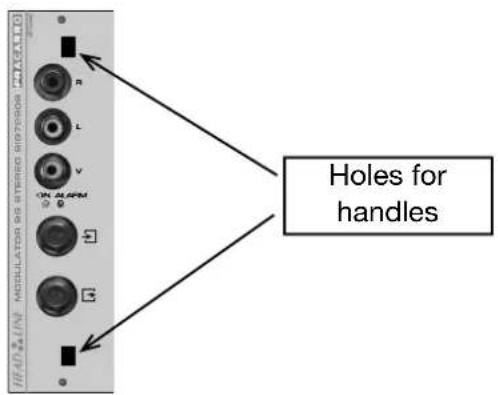
FRACARRO
natural_image
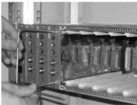
Close-up of a hand inserting a component into an electronic device housing (no visible text or symbols)Rotate the handles (extracting tools) by 90° to make one handle (see fig. 11).
Fig. 11
natural_image
Close-up of a hand inserting a component into an open electronic device panel (no visible text or symbols)Pull the handle gently with one hand to take the module out. Once the module has been detached from the back panel it can be removed smoothly using little force (see fig. 12).
Fig. 12
natural_image
Close-up of a hand inserting a component into a server rack (no visible text or symbols)When extracting the module be careful not to touch it as it may cause harm (see Fig. 13).
Fig. 13
IDENTIFYING THE MODULE
Once the modules have been installed they can be identified using the labels supplied. Inside the rack box there are two sheets with a list of numbers 1 to 11 to number the modules and another two sheets with numbers 2 to 69 to indicate the output channel of the modulator. The stickers with "MODULE NUMBER" identify the module position within the row. Stick the label with the number "1" to the first module after the interconnection module, the label with the number "2" to the second module and so on up to the 11th possible module. Stick the label to the top right of the front cover. The address of the module is now easily identifiable by looking at the display of the row and adding the number of the label (see fig. 14).
Fig. 14
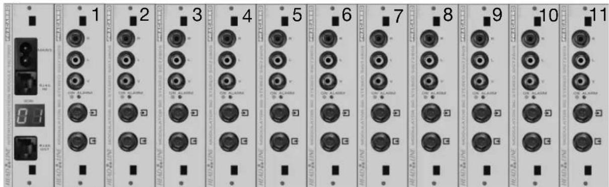
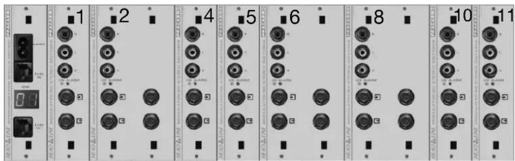
For double fronted modules the back panel positions should be respected so skip one position number taken up by the double module (see fi g. 15).
Fig. 15
After programming the interconnection modules with row numbers you can connect them all. Use the serial cable RJ45 (item PATCH-RJ45, code 289548 – to be bought separately) to connect the different interconnection modules together using ports RJ45IN and RJ45OUT (see fi g. 16).
Fig. 16
FRACARRO
TECHNICAL SPECIFICATIONS
| Mains | power | 220-240V~, | 50-60Hz |
| Power | consumption | 2W (stand alone) | |
| 100W max | |||
| Operating temperature | -5÷45°C | ||
| Back panel connections | 230V~, RS485 | ||
MODULE PROGRAMMING
It is now possible to program all the HEADLINE modules from one point.
Connect the TPE programmer to the 1st interconnection module using the RJ45IN socket (if there are more rows the RJ45OUT socket should be used by the PATCH-RJ45 cable).
Wait a few seconds for the TPE to search for all connected devices and create a map of the headend. The display will show information regarding devices found.
Once the search has been completed the Fracarro logo will be displayed. By pressing any button (except X) you will enter the programming menu.
Each module is uniquely identified by two numbers, the first is the row number and the second is the position number within the row. The row number is given by the interconnection module (shown on the display) while the position number is identified by the label (see the chapter "identifi cation of the module").
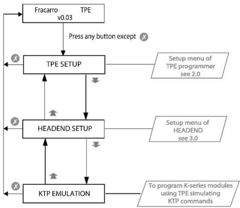
The diagram below shows the programming menu of the HEADLINE headend.
Refer to the operating instructions for each module to obtain information regarding their operation.
1.0 GENERAL MENU
flowchart
graph TD
    A["Fracarro TPE v0.03"] -->|Press any button except X| B["TPE SETUP"]
    B --> C["Setup menu of TPE programmer see 2.0"]
    B --> D["Setup menu of HEADEND see 3.0"]
    B --> E["HEADEND SETUP"]
    E --> F["KTP EMULATION"]
    F --> G["To program K-series modules using TPE simulating KTP commands"]
    A --> H["X"]
    B --> I["X"]
    C --> J["X"]
    D --> K["X"]
    E --> L["X"]
    F --> M["X"]
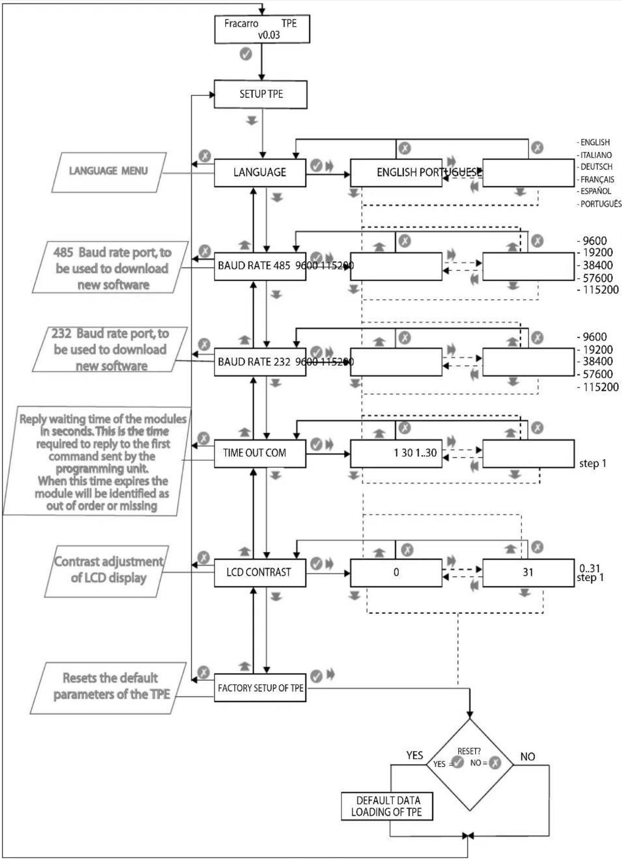
2.0 SETUP TPE
flowchart
```mermaid
graph TD
    A["Fracarro TPE v0.03"] --> B["SETUP TPE"]
    B --> C["LANGUAGE"]
    C --> D["LANGUAGE"]
    D --> E["BAUD RATE 485 9600-115200"]
    E --> F["BAUD RATE 232 9600-115200"]
    F --> G["TIME OUT COM"]
    G --> H["LCD CONTRAST"]
    H --> I["FACTORY SETUP OF TPE"]
    I --> J{RESET? NO = ?}
    J -->|YES| K["DEFAULT DATA LOADING OF TPE"]
    J -->|NO| L["OUTPUTING OUTPUT"]
    M["LANGUAGE MENU"] --> N["LANGUAGE"]
    O["485 Baud rate port, to be used to download new software"] --> P["LANGUAGE"]
    Q["232 Baud rate port, to be used to download new software"] --> R["LANGUAGE"]
    S["Reply waiting time of the modules in seconds. This is the time required to reply to the first command sent by the programming unit. When this time expires the module will be identified as out of order or missing"] --> T["LANGUAGE"]
    U["Contrast adjustment of LCD display"] --> V["PRODUCTUT"]
    W["Reset the default parameters of the TPE"] --> X["PRODUCTUT"]
    Y["ENGLISH PORTUGuese"] --> Z["LANGUAGE"]
    AA["ENGLISH ITALIANO DEUTSCH FRANÇAIS ESPANOL PORTUGUES"] --> AB["LANGUAGE"]
    AC["ENGLISH ENGLISH PORTUGuese"] --> AD["LANGUAGE"]
    AE["ENGLISH ENGLISH ITALIANO DEUTSCH FRANÇAIS ESPANOL PORTUGUES"] --> AF["LANGUAGE"]
    AG["ENGLISH ENGLISH ITALIANO DEUTSCH FRANÇAIS ESPANOL PORTUGUES"] --> AH["LANGUAGE"]
    AI["ENGLISH ENGLISH ITALIANO DEUTSCH FRANÇAIS ESPANOL PORTUGUES"] --> AJ["LANGUAGE"]
    AK["ENGLISH ENGLISH ITALIANO DEUTSCH FRANÇAIS ESPANOL PORTUGUES"] --> AL["LANGUAGE"]
    AM["ENGLISH ENGLISH ITALIANO DEUTSCH FRANÇAIS ESPANOL PORTUGUES"] --> AN["LANGUAGE"]
    AO["ENGLISH ENGLISH ITALIANO DEUTSCH FRANÇAIS ESPANOL PORTUGUES"] --> AP["LANGUAGE"]
    AQ["ENGLISH ENGLISH ITALIANO DEUTSCH FRANÇAIS ESPANOL PORTUGUES"] --> AR["LANGUAGE"]
    AS["ENGLISH ENGLISH ITALIANO DEUTSCH FRANÇAIS ESPANOL PORTUGUES"] --> AT["LANGUAGE"]
    AU["ENGLISH ENGLISH ITALIANO DEUTSCH FRANÇAIS ESPANOL PORTUGUES"] --> AV["LANGUAGE"]
    AW["ENGLISH ENGLISH ITALIANO DEUTSCH FRANÇAIS ESPANOL PORTUGUES"] --> AX["LANGUAGE"]
    AY["ENGLISH ENGLISH ITALIANO DEUTSCH FRANÇAIS ESPANOL PORTUGUES"] --> AZ["LANGUAGE"]
    BA["ENGLISH ENGLISH ITALIANO DEUTSCH FRANÇAIS ESPANOL PORTUGUES"] --> BB["LANGUAGE"]
    BC["ENGLISH ENGLISH ITALIANO DEUTSCH FRANÇAIS ESPANOL PORTUGUES"] --> BD["LANGUAGE"]
    BE["ENGLISH ENGLISH ITALIANO DEUTSCH FRANÇAIS ESPANOL PORTUGUES"] --> BF["LANGUAGE"]
    BG["ENGLISH ENGLISH ITALIANO DEUTSCH FRANÇAIS ESPANOL PORTUGUES"] --> BH["LANGUAGE"]
    BI["ENGLISH ENGLISH ITALIANO DEUTSCH FRANÇAIS ESPANOL PORTUGUES"] --> BJ["LANGUAGE"]
    BK["ENGLISH ENGLISH ITALIANO DEUTSCH FRANÇAIS ESPANOL PORTUGUES"] --> BL["LANGUAGE"]
    BM["ENGLISH ENGLISH ITALIANO DEUTSCH FRANÇAIS ESPANOL PORTUGUES"] --> BN["LANGUAGE"]
    BO["ENGLISH ENGLISH ITALIANO DEUTSCH FRANÇAIS ESPANOL PORTUGUES"] --> BP["LANGUAGE"]
    BQ["ENGLISH ENGLISH ITALIANO DEUTSCH FRANÇAIS ESPANOL PORTUGUES"] --> BQ
    CA["ENGLISH ENGLISH ITALIANO DEUTSCH FRANÇAIS ESPANOL PORTUGUES"] --> CB["LANGUAGE"]
    CC["ENGLISH ENGLISH ITALIANO DEUTSCH FRANÇAIS ESPANOL PORTUGUES"] --> CD["LANGUAGE"]
    CE["ENGLISH ENGLISH ITALIANO DEUTSCH FRANÇAIS ESPANOL PORTUGUES"] --> CF["LANGUAGE"]
    CG["ENGLISH ENGLISH ITALIANO DEUTSCH FRANÇAIS ESPANOL PORTUGUES"] --> DH["LANGUAGE"]
    DI["ENGLISH ENGLISH ITALIANO DEUTSCH FRANÇAIS ESPANOL PORTUGUES"] --> DJ["LANGUAGE"]
    DK["ENGLISH ENGLISH ITALIANO DEUTSCH FRANÇAIS ESPANOL PORTUGUES"] --> DL["LANGUAGE"]
    DV["ENGLISH ENGLISH ITALIANO DEUTSCH FRANÇAIS ESPANOL PORTUGUES"] --> DW["LANGUAGE"]
    DX["ENGLISH ENGLISH ITALIANO DEUTSCH FRANÇAIS ESPANOL PORTUGUES"] --> DY["LANGUAGE"]
    DB["ENGLISH ENGLISH ITALIANO DEUTSCH FRANÇAIS ESPANOL PORTUGUES"] --> DB
    DCX["ENGLISH ENGLISH ITALIANO DEUTSCH FRANÇAIS ESPANOL PORTUGUES"] --> CY["LANGUAGE"]
    DD[XELENTATION DETAILMENT DETAILMENT DETAILMENT DETAILMENT DETAILMENT DETAILMENT DETAILMENT DETAILMENT DETAILMENT DETAILMENT DETAILMENT DETAILMENT DETAILMENT DETAILMENT DETAILMENT DETAILMENT DETAILMENT DETAILMENT DETAILMENT DETAILMENT DETAILMENT DETAILMENT DETAILMENT DETAILMENT DETAILMENT DETAILMENT DETAILMENT DETAILMENT DETAILMENT DETAILMENT DETAILMENT DETAILMENT DETAILMENT DETAILMENT RETAILMENT DETAILMENT DETAILMENT DETAILMENT DETAILMENT DETAILMENT DETAILMENT DETAILMENT DETAILMENT DETAILMENT DETAILMENT DETAILMENT DETAILMENT DETAILMENT DETAILMENT DETAILMENT DETAILMENT DETAILMENT DETAILMENT DETAILMENT DETAILMENT DETAILMENT DETAILMENT DETAILMENT DETAILMENT DETAILMENT DETAILMENT DETAILMENT DETAILMENT DETAILMENT DETAILMENT DETAILMENT DETAILMENT DETILENTETAILMENT DetAILMENT DETAILMENT DETAILMENT DETAILMENT DETAILMENT DETAILMENT DETAILMENT DETAILMENT DETAILMENT DETAILMENT DETAILMENT DETAILMENT DETAILMENT DETAILMENT DETAILMENT DETAILMENT DETAILMENT DETAILMENT DETAILMENT DETAILMENT DETAILMENT DETAILMENT DETAILMENT DETAILMENT DETAILMENT DETAILMENT DETAILMENT DETAILMENT DETAILMENT DETAILMENT DETAILMENT DETAILMENT DETAILMENT DETIRETTETAILMENT DetAILMENT DetAILMENT DetAILMENT DetAILMENT DetAILMENT DetAILMENT DetAILMENT DetAILMENT DetAILMENT DetAILMENT DetAILMENT DetAILMENT DetAILMENT DetAILMENT DetAILMENT DetAILMENT DetAILMENT DetAILMENT DetAILMENT DetAILMENT DetAILMENT DetAILMENT DetAILMENT DetAILMENT DetAILMENT DetAILMENT DetAILMENT DetAILMENT DetAILMTETAILMDETAILMDETAILMDETAILMDETAILMDETAILMDETAILMDETAILMDETAILMDETAILMDETAILMDETAILMDETAILMDETAILMDETAILMDETAILMDETAILMDETAILMDETAILMDETAILMDETAILMDETAILMDETAILMDETAILMDETAILMDETAILMDETAILMDETAILMDETAILMDETAILMDETAILMDETAILMDETAILMDETAILMDETATTEMETAILMDETATTEMETAILMDETATTEMETAILMDETATTEMETAILMDETATTEMETAILMDETATTEMETAILMDETATTEMETAILMDETATTEMETAILMDETATTEMETAILMDETATTEMETAILMDETATTEMETAILMDETATTEMETAILMDETATTEMETAILMDETATTEMETAILMDETATTEMETILENTETILENTETILENTETILENTETILENTETILENTETILENTETILENTETILENTETILENTETILENTETILENTETILENTETILENTETILENTETILENTETILENTETILENTETILENTETILENTETILENTETILENTETILENTETILENTETILENTETILENTETILENTETILENTETILENTETILENTETILENTETILENTETILENTETILENTTETILENTTETILENTTETILENTTETILENTTETILENTTETILENTTETILENTTETILENTTETILENTTETILENTTETILENTTETILENTTETILENTTETILENTTETILENTTETILENTTETILENTTETILENTTETILENTTETILENTTETILENTTETILENTTETILENTTETILENTTETILENTNFTILENTNFTILENTNFTILENTNFTILENTNFTILENTNFTILENTNFTILENTNFTILENTNFTILENTNFTILENTNFTILENTNFTILENTNFTILENTNFTILENTNFTILENTNFTILENTNFTILENTNFTILENTNFTILENTNFTILENTNFTILENTNFTILENTNFTILENTNFTILENTNFTILENTNCTURENDGETTCPNETTCPNETTCPNETTCPNETTCPNETTCPNETTCPNETTCPNETTCPNETTCPNETTCPNETTCPNETTCPNETTCPNETTCPNETTCPNETTCPNETTCPNETTCPNETTCPNETTCPNETTCPNETTCPNETTCPNETTCPNETTCPNETTCPNETTCPNETTCPNETTCPNETTCPNETTCPNETTCPNETTCPNETTCPNETTCPNETTCPNETTCPNETTCPNETTCPNETTCPNETTCPNETTCPNETTCPNETTCPNETTCPNETTCPNETTCPNETTCPNETTCPNETTCPINTSETTCSETTCSETTCSETTCSETTCSETTCSETTCSETTCSETTCSETTCSETTCSETTCSETTCSETTCSETTCSETTCSETTCSETTCSETTCSETTCSETTCSETTCSETTCSETTCSETTCSETTCSETTCSETTCSETTCSETTCSETTCSETTCSETTCSETTCSETTCSETTCSETTCSETTCSETTCSETTCSETTCSETTCSETTCSETTCSETTCSETTCSETTCSETTCSETTCSETTCSETTSETTCSETTCSETTCSETTCSETTCSETTCSETTCSETTCSETTCSETTCSETTCSETTCSETTCSETTCSETTCSETTCSETTCSETTCSETTCSETTCSETTCSETTCSETTCSETTCSETTCSETTCSETTCSETTCSETTCSETTCSETTCSETTCSETTCSETTCSETTCSETTCSETTCSETTCSETTCSETTCSETTCSETTCSETTCSETTCSETTCSETTCSETTCSETTCSETTCSETTGTSSTGTSSTGTSSTGTSSTGTSSTGTSSTGTSSTGTSSTGTSSTGTSSTGTSSTGTSSTGTSSTGTSSTGTSSTGTSSTGTSSTGTSSTGTSSTGTSSTGTSSTGTSSTGTSSTGTSSTGTSSTGTSSTGTSSTGTSSTGTSSTGTSSTGTSSTGTSSTGTSSTGTSSTG TSSTGTSSTGTSSTGTSSTGTSSTGTSSTGTSSTGTSSTGTSSTGTSSTGTSSTGTSSTGTSSTGTSSTGTSSTGTSSTGTSSTGTSSTGTSSTGTSSTGTSSTGTSSTGTSSTGTSSTGTSSTGTSSTGTSSTGTSSTGTSSTGTSSTGTSSTGTS STGTS STGTS STGTS STGTS STGTS STGTS STGTS STGTS STGTS STGTS STGTS STGTS STGTS STGTS STGTS STGTS STGTS STGTS STGTS STGTS STGTS STGTS STGTS STGTS STGTS STGTS STGTS STGTS STG<fcel>INTERNATIONAL
LANGUAGE
485 Baud rate port, to be used to download new software
232 Baud rate port, to be used to download new software
Reply waiting time of the modules in seconds. This is the time required to reply to the first command sent by the programming unit. When this time expires the module will be identified as out of order or missing
Contrast adjustment of LCD display
Reset the default parameters of the TPE
RETURN TO RESET
RETURN TO RESET
RETURN TO RESET
RETURN TO RESET
RETURN TO RESET
RETURN TO RESET
RETURN TO RESET
RETURN TO RESET
RETURN TO RESET
RETURN TO RESET
RETURN TO RESET
RETURN TO RESET
RETURN TO RESET
RETURN TO RESET
RETURN TO RESET
RETURN TO RESET
RETURN TO RESET
RETURN TO RESET
RETURN TO RESET
RETURN TO RESET
RETURN TO RESET
RETURN TO RESET
RETURN TO RESET
RETURN TO RESET
RETURN TO RESET
RETURN TO RETAIN
RETURN TO RETAIN
RETURN TO RETAIN
RETURN TO RETAIN
RETURN TO RETAIN
RETURN TO RETAIN
RETURN TO RETAIN
RETURN TO RETAIN
RETURN TO RETAIN
RETURN TO RETAIN
RETURN TO RETAIN
RETURN TO RETAIN
RETURN TO RETAIN
RETURN TO RETAIN
RETURN TO RETAIN
RETURN TO RETAIN
RETURN TO RETAIN
RETURN TO RETAIN
RETURN TO RETAIN
RETURN TO RETAIN
RETURN TO RETIN
RETURN TO RETIN
RETURN TO RETIN
RETURN TO RETIN
RETURN TO RETIN
RETURN TO RETIN
RETURN TO RETIN
RETURN TO RETIN
RETURN TO RETIN
RETURN TO RETIN
RETURN TO RETIN
RETURN TO RETIN
RETURN TO RETIN
RETURN TO RETIN
RETURN TO RETIN
RETURN TO RETIN
RETURN TO RETIN
RETURN TO RETIN
RETURN TO RETIN
RETURN TO RETIN
RETURN TO RETIT
RETURN TO RETIT
RETURN TO RETIT
RETURN TO RETIT
RETURN TO RETIT
RETURN TO RETIT
RETURN TO RETIT
RETURN TO RETIT
RETURN TO RETIT
RETURN TO RETIT
RETURN TO RETIT
RETURN TO RETIT
RETURN TO RETIT
RETURN TO RETIT
RETURN TO RETIT
RETURN TO RETIT
RETURN TO RETIT
RETURN TO RETIT
RETURN TO RETIT
RETURN TO RETIT
RETURN TO RETI
RETURN TO RETIT
RETURN TO RETIT
RETURN TO RETIT
RETURN TO RETIT
RETURN TO RETIT
RETURN TO RETIT
RETURN TO RETIT
RETURN TO RETIT
RETURN TO RETIT
RETURN TO RETIT
RETURN TO RETIT
RETURN TO RETIT
RETURN TO RETIT
RETURN TO RETIT
RETURN TO RETIT
RETURN TO RETIT
RETURN TO RETIT
RETURN TO RETIT
RETURN TO RETIT
RETURN TO RETII
RETURN TO RETII
RETURN TO RETII
RETURN TO RETII
RETURN TO RETII
RETURN TO RETII
RETURN TO RETII
RETURN TO RETII
RETURN TO RETII
RETURN TO RETII
RETURN TO RETII
RETURN TO RETII
RETURN TO RETII
RETURN TO RETII
RETURN TO RetIII<fcel>INTERNATIONAL
LANGUAGE<fcel>485 Baud rate port, to be used to download new software<fcel>232 Baud rate port, to be used to download new software<fcel>Reply waiting time of the modules in seconds. This is the time required to reply to the first command sent by the programming unit. When this time expires the module will be identified as out of order or missing<fcel>Contrast adjustment of LCD display<fcel>Reset the default parameters of the TPE<fcel>RETURN TO RESET<fcel>RETURN TO RESET<fcel>RETURN TO RESET<fcel>RETURN TO RESET<fcel>RETURN TO RESET<fcel>RETURN TO RESET<fcel>RETURN TO RESET<nl>
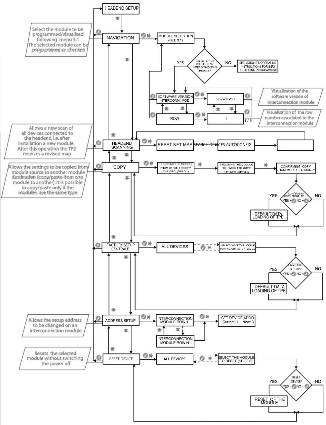
3.0 CENTRAL SETUP
ENGLISH
flowchart
graph TD
    A["HEADEND SETUP"] --> B["NAVIGATION"]
    B --> C["MODULE SELECTION (SEE 3.1)"]
    C --> D{THE SELECTED MODULE IS AN INTERCONNECTION MODULE?}
    D -->|YES| E["NO"]
    D -->|YES| F["SEE MODULE'S OPERATING INSTRUCTIONS FOR INFO REGARDING PROGRAMMING"]
    E --> G["SOFTWARE VERSION INTERCONN. MOD."]
    G --> H["SIG7900 V0.1"]
    H --> I["ROW"]
    I --> J["1"]
    J --> K["1..15"]
    K --> L["Visualisation of the software version of interconnection module"]
    L --> M["Visualisation of the row number associated to the interconnection module"]
    M --> N["RESET NET MAP"]
    N --> O["SEARCH DEVICES AUTOCONFIG"]
    O --> P["VALID"]
    P --> Q["HEADEND SCANNING"]
    Q --> R["COPY"]
    R --> S["CHOOING THE MODULE FROM WHICH TO COPY THE INFO (SEE 3.1)"]
    S --> T["CHOOING THE MODULE TO WHICH TO COPY THE INFO (SEE 3.1)"]
    T --> U["CONFIRMING COPY FROM MOD. X TO MOD. Y"]
    U --> V{CONFIRMING COPY FROM TO YES = NO = ?}
    V -->|YES| W["DEFAULT DATA LOADING OF TPE"]
    V -->|NO| X["VALID"]
    X --> Y["FACTORY SETUP CENTRALE"]
    Y --> Z["ALL DEVICES"]
    Z --> AA{SELECTION OF THE MODULE FOR FACTORY SETUP (SEE 3.2)}
    AA -->|YES| AB{FACTORY SETUP? YES = NO = ?}
    AB -->|NO| AC["DEFAULT DATA LOADING OF TPE"]
    AB -->|NO| AD["VALID"]
    AD --> AE["ADDRESS SETUP"]
    AE --> AF["INTERCONNECTION MODULE ROW 1"]
    AF --> AG["SET DEVICE ADDR Current: 1 New: 3"]
    AG --> AH["INTERCONNECTION MODULE ROW N"]
    AH --> AI["RESET DEVICE"]
    AI --> AJ["ALL DEVICES"]
    AJ --> AK{SELECT THE MODULE TO RESET (SEE 3.2)}
    AK -->|YES| AL{RESET DEVICE? YES = NO = ?}
    AL -->|NO| AM["RESET OF THE MODULE"]
    AL -->|NO| AN["VALID"]
    AN --> AO["ADDRESS SETUP"]
    AO --> AP["INTERSUMPTION AND SWITCH WITH INPUTS"]
    AP --> AQ["RESET DEVICE"]
    AQ --> AR["RESET OF THE MODULE"]
    AR --> AS["RESET OF THE MODULE"]
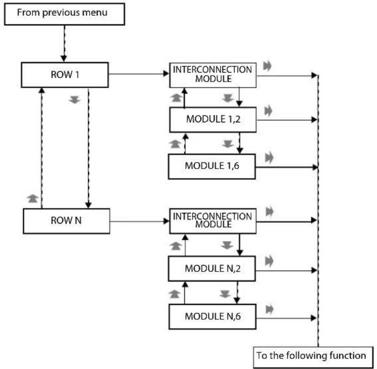
3.1 MODULE SELECTION FOR NAVIGATION
flowchart
graph TD
    A["From previous menu"] --> B["ROW 1"]
    B --> C["INTERCONNECTION MODULE"]
    C --> D["MODULE 1,2"]
    D --> E["MODULE 1,6"]
    E --> F["To the following function"]
    B --> G["ROW N"]
    G --> H["INTERCONNECTION MODULE"]
    H --> I["MODULE N,2"]
    I --> J["MODULE N,6"]
    J --> F
    C --> K["->"]
    D --> L["->"]
    E --> M["->"]
    F --> N["->"]
    G --> O["->"]
    H --> P["->"]
    I --> Q["->"]
    J --> R["->"]
    K --> S["->"]
    L --> T["->"]
    M --> U["->"]
    N --> V["->"]
    O --> W["->"]
    P --> X["->"]
    Q --> Y["->"]
    R --> Z["->"]
    S --> AA["->"]
    T --> AB["->"]
    U --> AC["->"]
    V --> AD["->"]
    W --> AE["->"]
    X --> AF["->"]
    Y --> AG["->"]
    Z --> AH["->"]
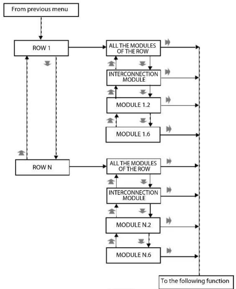
3.2 MODULE SELECTION FOR NAVIGATION (FACTORY SETUP FUNCTION)
flowchart
graph TD
    A["From previous menu"] --> B["ROW 1"]
    B --> C["ALL THE MODULES OF THE ROW"]
    C --> D["INTERCONNECTION MODULE"]
    D --> E["MODULE 1.2"]
    E --> F["MODULE 1.6"]
    F --> G["To the following function"]
    B --> H["ROW N"]
    H --> I["ALL THE MODULES OF THE ROW"]
    I --> J["INTERCONNECTION MODULE"]
    J --> K["MODULE N.2"]
    K --> L["MODULE N.6"]
    L --> G
    C --> M["->"]
    D --> N["->"]
    E --> O["->"]
    F --> P["->"]
    G --> Q["->"]
    H --> R["->"]
    I --> S["->"]
    J --> T["->"]
    K --> U["->"]
    L --> V["->"]
    M --> W["->"]
    N --> X["->"]
    O --> Y["->"]
    P --> Z["->"]
    Q --> AA["->"]
    R --> AB["->"]
    S --> AC["->"]
    T --> AD["->"]
    U --> AE["->"]
    V --> AF["->"]
    W --> AG["->"]
    X --> AH["->"]
    Y --> AI["->"]
    Z --> AJ["->"]
    AA --> AK["->"]
    AB --> AL["->"]
    AC --> AM["->"]
    AD --> AN["->"]
    AE --> AO["->"]
    AF --> AP["->"]
    AG --> AQ["->"]
    AH --> AR["->"]
    AI --> AS["->"]
    AJ --> AT["->"]
    AK --> AU["->"]
    AL --> AV["->"]
    AM --> AW["->"]
    AN --> AX["->"]
    AO --> AY["->"]
    AP --> AZ["->"]
    AQ --> BA["->"]
    AR --> BB["->"]
    AS --> BC["->"]
    AT --> BD["->"]
    AU --> BE["->"]
    AV --> BF["->"]
    AW --> BG["->"]
    AX --> BH["->"]
    AY --> BI["->"]
INSTRUCTIONS DE SECURITE
natural_image
Person operating a FRACARRO industrial control unit with visible circuit board (no text or symbols on main subject)natural_image
Interior view of an electrical enclosure labeled 'FRACARRO' with hands installing components (no readable text beyond label)natural_image
Person installing or adjusting an electrical enclosure labeled 'FRACARRO' (no other text visible)Fig. 4

natural_image
Interior view of a FRACARRO industrial control cabinet with open doors and internal modules (no visible text or symbols)FRACARRO
Fig. 5
natural_image
Interior view of an electronic server rack with multiple drive bays and a cable inserted (no visible text or labels)natural_image
Close-up of an electronic control panel with a digital display and connector, no visible text or symbolsFig. 7

natural_image
Close-up of hands installing a cable on an open server rack with multiple circuit modules (no visible text or symbols)natural_image
Close-up of hands installing or adjusting a server rack with an open panel showing internal components (no visible text or symbols)natural_image
Close-up of a hand inserting a computer into an open drive bay (no visible text or symbols)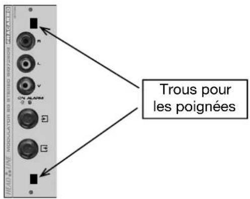
natural_image
Close-up of hands installing or adjusting an electronic device panel with buttons and connectors (no visible text or symbols)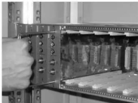
natural_image
Close-up of a hand inserting a component into an open server rack (no visible text or symbols)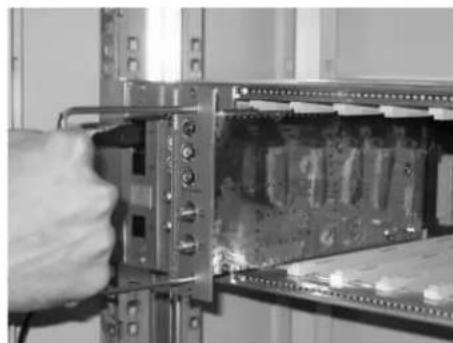
natural_image
Close-up of a hand inserting a component into a server rack (no visible text or symbols)natural_image
Person operating a FRACARRO electrical enclosure with visible circuitry and components (no text or symbols on main subject)natural_image
Interior view of a FRACARRO electrical enclosure with open doors and internal modules (no visible text or symbols)natural_image
Person installing or adjusting a FRACARRO electrical enclosure panel (no visible text or symbols on the device itself)Fig. 4

natural_image
Interior view of an open industrial control cabinet labeled 'FRACARRO' with internal modules and a hand holding the door (no readable text beyond label)FRACARRO
Fig. 5

natural_image
Interior view of an electronic device showing internal circuitry and connectors (no visible text or symbols)natural_image
Interior view of an electronic device rack with a digital display and cable (no visible text or symbols)Fig. 7

natural_image
Close-up of hands installing a cable on an open server rack with circuit boards (no visible text or symbols)natural_image
Close-up of hands installing or adjusting a computer rack with visible circuit boards and connectors (no text or symbols)natural_image
Close-up of a hand inserting a computer into an open drive bay (no visible text or symbols)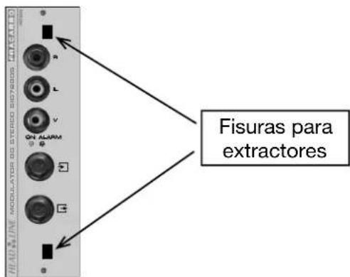
FRACARRO
natural_image
Close-up of a hand holding an electronic device with ports and connectors (no visible text or symbols)natural_image
Close-up of a hand inserting a component into an open electrical panel (no visible text or symbols)natural_image
Close-up of a hand inserting a component into a server rack (no visible text or symbols)natural_image
Person operating a FRACARRO industrial control unit with visible circuit board (no text or symbols on the device itself)natural_image
Interior view of an electrical enclosure labeled 'FRACARRO' with open doors and internal components (no readable text beyond label)natural_image
Interior view of an electrical enclosure labeled 'FRACARRO' with hands operating the panel (no visible text beyond label)Fig. 4
natural_image
Interior view of a FRACARRO industrial control cabinet with open doors and internal modules (no visible text or symbols)FRACARRO
Fig. 5

natural_image
Interior view of an electronic device showing internal components and a connected cable (no visible text or symbols)natural_image
Interior view of an electronic device rack with a black cable inserted, showing internal components and a digital display (no visible text or symbols)Fig. 7

natural_image
Close-up of hands installing a cable on an open server rack with circuit boards (no visible text or symbols)natural_image
Close-up of hands installing a cable on an open server rack with internal circuit boards (no visible text or symbols)natural_image
Close-up of a hand inserting a cable into an open computer RAM module (no visible text or symbols)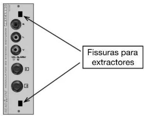
natural_image
Person operating a FRACARRO electrical enclosure with multiple vials (no visible text or symbols)natural_image
Interior view of a FRACARRO industrial machine with open panel and control panel (no visible text or symbols)natural_image
Interior view of a FRACARRO electrical enclosure with open panel and hand operating controls (no visible text or symbols)Abb. 4
natural_image
Interior view of a FRACARRO industrial control cabinet with open doors and internal modules (no visible text or symbols)FRACARRO
Abb. 5

natural_image
Interior view of an electronic device showing internal circuitry and connectors (no visible text or symbols)natural_image
Close-up of an electronic device rack with a digital display and cable, no visible text or symbolsAbb. 7

natural_image
Close-up of hands installing or adjusting a server rack with visible circuit boards and connectors (no text or symbols)natural_image
Close-up of hands installing or adjusting a server rack with an open panel showing internal circuitry (no visible text or symbols)natural_image
Close-up of a hand inserting a component into an electronic circuit board (no visible text or symbols)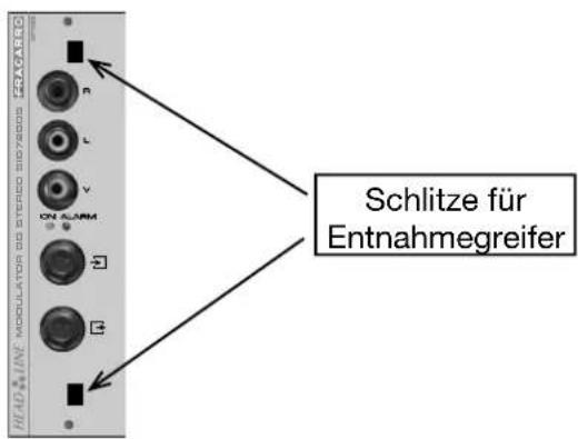
natural_image
Close-up of a hand inserting a device into an open rack-mounted server or memory unit (no visible text or symbols)natural_image
Close-up of a hand inserting a component into an open electrical enclosure with battery modules (no visible text or symbols)natural_image
Close-up of a hand inserting a component into a server rack (no visible text or symbols)Abb. 12

Brand : FRACARRO
Model : SIG7900
Category : Electronic module