
SIG7120 - Digital modulator FRACARRO - Free user manual and instructions
Find the device manual for free SIG7120 FRACARRO in PDF.
| Product type | DVB-T COFDM digital modulator |
| Brand | Fracarro |
| Model | SIG7120 |
| Transport Stream input | Parallel on back-panel (48 pins) |
| RF output | F female connector, frequency 111-862 MHz |
| Modulation | DVB-T (COFDM): QPSK, 16QAM, 64QAM |
| Bandwidth | 6, 7, 8 MHz |
| FEC | 1/2, 2/3, 3/4, 5/6, 7/8 |
| Guard interval | 1/4, 1/8, 1/16, 1/32 |
| Carriers | 2K, 8K |
| Max. output level | 85 ± 2 dBμV, adjustable 0-15 dB (1 dB steps) |
| Power supply | 184-264 VAC, 50/60 Hz, Class II, 10 W max |
| Operating temperature | -10 to +45 °C |
| LED indicators | 2 LEDs (green and red) for status and alarms |
| Programming | Via TPE programmer (not included) |
| Max. number of channels | 32 |
| Max. bitrate parallel input | 100 Mbit/s |
| Compliance | EMC directives 2004/108/EC, Low Voltage 2006/95/EC |
| Installation | In 19" rack (New HeadLine series, ref. SIG7901/SIG7902) |
Frequently Asked Questions - SIG7120 FRACARRO
User questions about SIG7120 FRACARRO
0 question about this device. Answer the ones you know or ask your own.
Ask a new question about this device
Download the instructions for your Digital modulator in PDF format for free! Find your manual SIG7120 - FRACARRO and take your electronic device back in hand. On this page are published all the documents necessary for the use of your device. SIG7120 by FRACARRO.
USER MANUAL SIG7120 FRACARRO
natural_image
Person installing or adjusting a device panel with a ruler, labeled 'Fig. 1' (no readable text on components)natural_image
Close-up of a hand holding a yellow tool next to an open electronic device panel (no visible text or symbols)natural_image
Close-up of a hand inserting electronic components into an open industrial control panel (no visible text or symbols)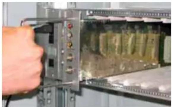
natural_image
Close-up of a hand inserting a component into an electronic device panel (no visible text or symbols)4. ISTRUZIONI PER L'UTILIZZO
flowchart
Italian software architecture flowchart for a list of canals, showing data flow between LISTA CANALI, GESTIONE PID, and various PID operations.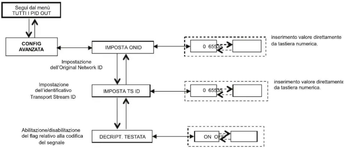
The product must be installed only by qualified persons, according to the local safety standards and regulations. It is classified as Class II, in accordance with EN 60065 and, for this reason, it shall not be connected to the protective earth (PE) of the supply mains. The product must be installed in an Headline Sub-rack and it must not be connected directly with an external power cable.
Installation warnings
- The product must not be exposed to dripping or splashing and thus it shall be installed indoors, in a dry place.
- Humidity and condensation could damage the product. In case of condensation, wait until the product is dry before using it.
- Don't install the product above or close to heat sources, in dusty places or where it might come into contact with corrosive substances.
- Leave enough space around the product housing to ensure sufficient ventilation; an excessive operating temperature and/or an excessive heating may affect the performance and the life of the product.
- To prevent injury, this product must be securely connected to a Sub-rack, in accordance with the mounting instructions, given in Chapter 3.
In accordance with the European Directive 2004/108/EC (EMC), the product shall be installed using devices, cables and connectors that allow to comply with this directive requirements for fixed installations.
Earthing of the antenna system
The Sub-rack, where the unit will be installed, must be connected, directly or through the rack, to the earth electrode of the antenna system, in accordance with standard EN 50083-1, section 10. It is recommended to follow the provisions of EN 50083-1 and not to connect the Sub-rack or the rack to the protective earth (PE) of the supply mains.
IMPORTANT: Never remove the product cover, parts at hazardous voltage could be accessible when the product case is opened. Only instructed and authorized persons can open the product. In case of failure, do not try to repair the product; otherwise the guarantee will no longer be valid.
2. PRODUCT DESCRIPTION
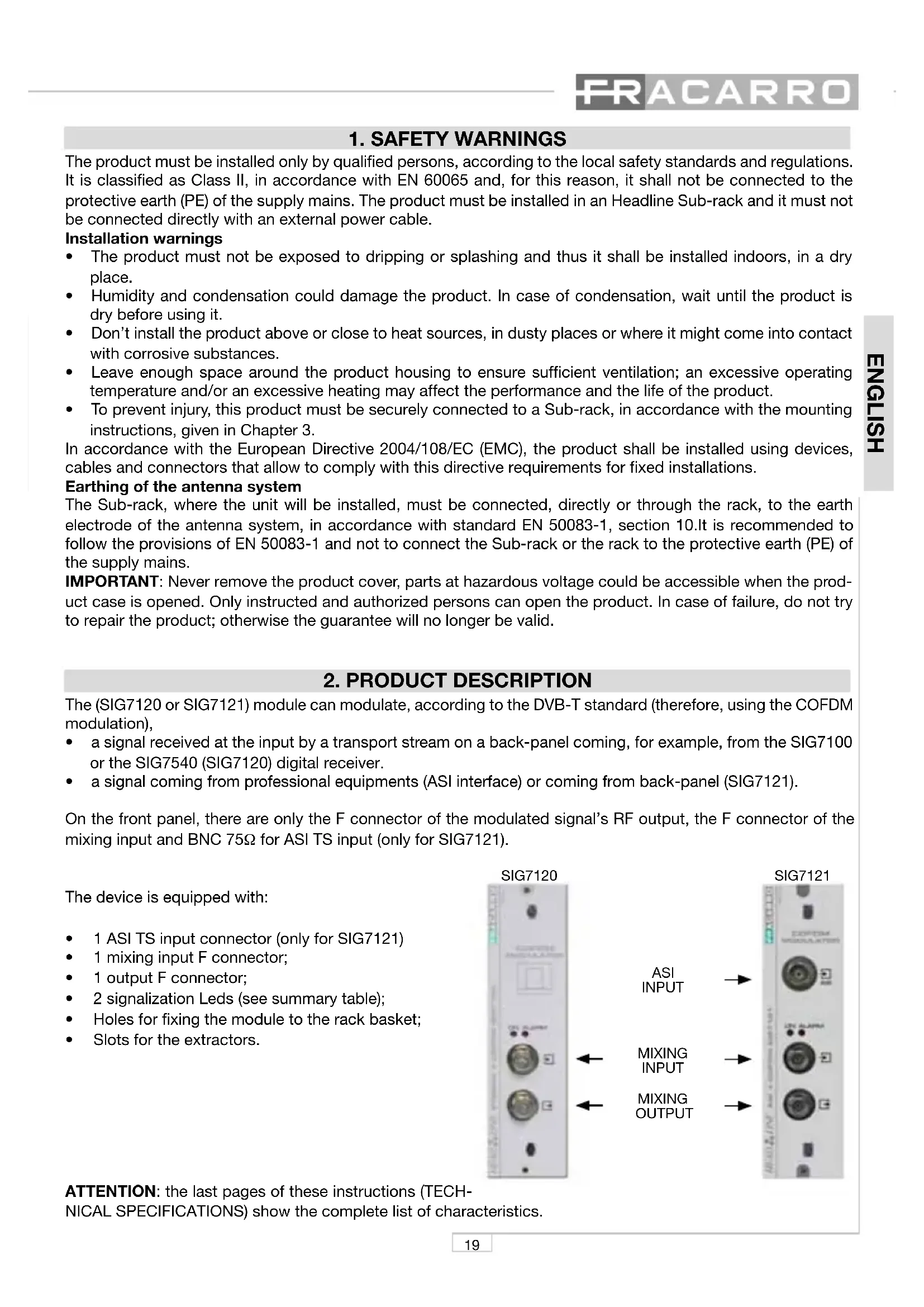
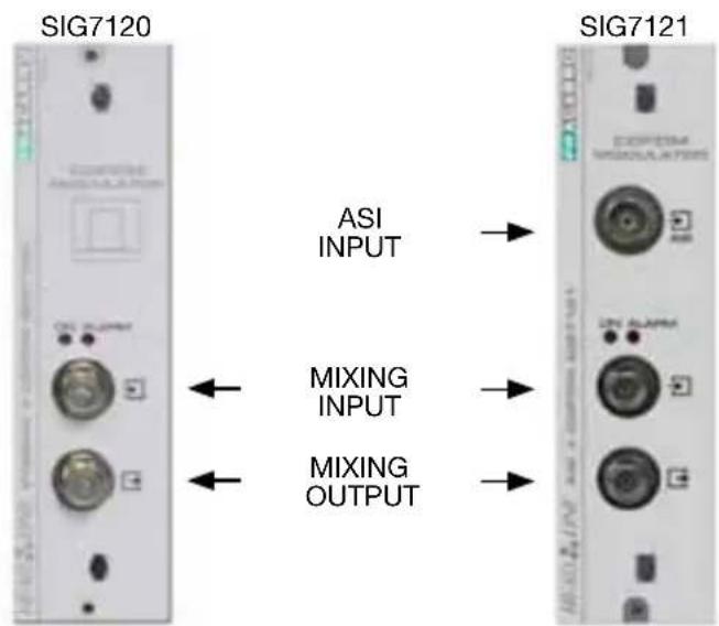
The (SIG7120 or SIG7121) module can modulate, according to the DVB-T standard (therefore, using the COFDM modulation),
- a signal received at the input by a transport stream on a back-panel coming, for example, from the SIG7100 or the SIG7540 (SIG7120) digital receiver.
- a signal coming from professional equipments (ASI interface) or coming from back-panel (SIG7121).
On the front panel, there are only the F connector of the modulated signal's RF output, the F connector of the mixing input and BNC 75Ω for ASI TS input (only for SIG7121).
The device is equipped with:
• 1 ASI TS input connector (only for SIG7121)
• 1 mixing input F connector;
• 1 output F connector;
• 2 signalization Leds (see summary table);
• Holes for fixing the module to the rack basket;
• Slots for the extractors.
ATTENTION: the last pages of these instructions (TECH-NICAL SPECIFICATIONS) show the complete list of characteristics.
3. PRODUCT INSTALLATION
The (SIG7120 or SIG7121) module is installed in the sub-rack of the NewHead Line (SIG7901 or SIG7902) series as per the following photos. Take the module out of its packaging and install it in the required position. The packing contains the following parts:
• SIG7120 or SIG7121 module;
• N° 3 fast jumpers for the interconnection (KPR41);
• 75ohm load (CA75F).

natural_image
Person using a tool to install or install electronic components in a rack (no visible text or symbols)After the insertion, fix the module using the screws contained in the accessory bag. It's a "plug and play" installation; therefore, the module is ready to operate.
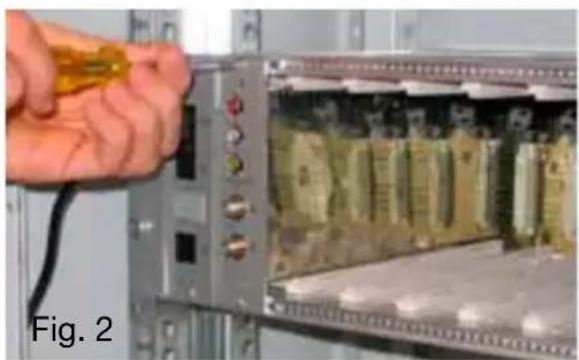
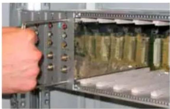
Insert the module in the card guides and gently push back to lock them to the back-panel.
natural_image
Close-up of a hand holding a yellow cable next to an open electronic device with circuitry (no visible text or symbols)To remove the module use the handles included in the New Headline sub-rack. Remove from the back-panel the screws of the module's to be replaced and insert the extractors into the rectangular slots. Rotate the extractors 90^ to form a handle. Pull the handle with your hand to extract the module. Be careful because, after a first effort to detach the module from the bottom panel connectors, the module can be easily removed. While removing the module, be careful not to touch the covers because they can cause small grazes.
natural_image
Close-up of a hand inserting electronic components into an open circuit board (no visible text or symbols)
natural_image
Close-up of a hand inserting a component into an electronic device panel (no visible text or symbols)4. OPERATION INSTRUCTIONS
To correctly install and configure the (SIG7120 or SIG7121) module, follow the operations listed below:
- Install the module on the 19" sub-rack (SIG7901 or SIG7902) as explained before;
- Use the supplied rigid jumper to connect the signal to other compatible New HeadLine modules (if present);
- Connect the power supply to the 19" sub-rack;
- Wait for the initialization of the module (the green LED flashes rapidly and the red LED is on);
- Connect the TPE to the interconnection module of the 19" sub-rack and carry out the programming operations as specified in Chapter 5. PROGRAMMING INSTRUCTIONS.
IMPORTANT: The module needs about 30 seconds to complete the initial start-up phase and configure the system; therefore, wait for the phase to be completed before starting any programming by means of the TPE. Otherwise, the module might not be seen by the programmer and a new scanning of the head-end could be necessary before being able to start programming it.
LEDs status table:
| Green LED Red LED Meaning | ||
| OFF OFF The modulator is off | ||
| Rapid flashing ON The modulator is in the start-up and system configuration phase | ||
| Slow flashing ON Modulator boot-up | ||
| ON OFF Modulator fed correctly and Transport Stream detected at the input | ||
| ON Slow flashing | Modulator fed correctly but no Transport Stream is detected at the input | |
| ON Rapid flashing Modulator under an overheating or overflow alarm | ||
| Slow Flashing OFF Slow flashing | Presence of new parameters in the modulator not yet saved | |
| ON ON Modulator fed correctly but there is an internal anomaly |
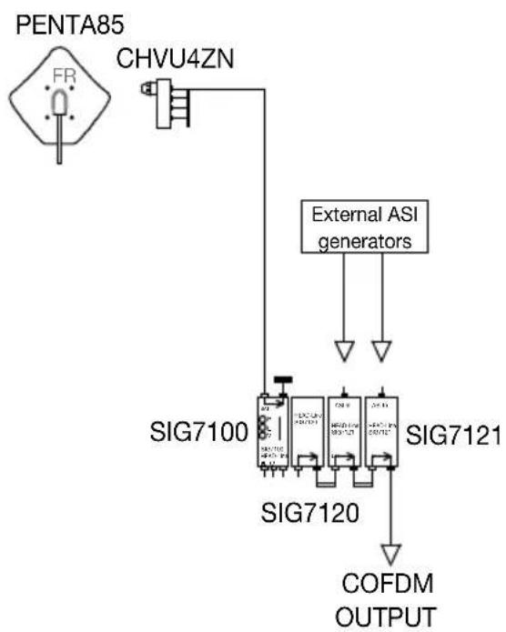
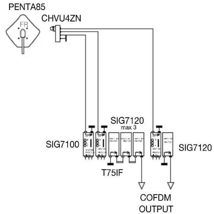
4.1 TYPICAL INSTALLATION EXAMPLE
flowchart
graph TD
    A["PENTA85"] --> B["CHVU4ZN"]
    B --> C["External ASI generators"]
    C --> D["SIG7100"]
    C --> E["SIG7120"]
    C --> F["SIG7121"]
    D --> G["COFDM OUTPUT"]
    E --> G
    F --> G
5. PROGRAMMING INSTRUCTIONS
The (SIG7120 or SIG7121) module programming is carried out by using the universal TPE programmer by which all the main functioning parameters can be set.
To program by means of the TPE, it is sufficient to connect the programmer to the interconnection module (SIG7900) of the New HeadLine. After waiting for the automatic scanning of all the modules in the headend, it will be possible to access all the available modules as well as the module to be programmed. Refer to the paragraph "HEADEND SETUP MENU AND KTP EMULATION".
IMPORTANT: After connecting the module to the panel, wait for the start-up phase and the system configuration to be completed. It will take about 30 seconds to correctly identify the module. If, during the programming, the TPE often shows the word "Wait ..." (for example during the scrolling of the channel list), it can be useful to increase the TIMEOUT value (30) of the TPE programmer (set by default at 12 seconds). To do that, enter the "SETUP TPE" – "TIMEOUT COM" menu (refer to the SETUP TPE menu).
IMPORTANT: by using the SIG7905 interface (Controller Host module), it is possible to check the status of the module and program it remotely. For further information, refer to the instructions of the SIG7905 module.
IMPORTANT: to save the set parameters, press the key of the TPE. If the key is not pressed within 5 minutes from the last modification, the set data will be lost and the previous values will be restored.
For further analysis of the TPE functions and menu, see the following paragraph.
Refer to the legend of the following tables for information relevant to programming activities and the interpretation of the programming menus indicated in the flow-charts.
| TPE keys | Key Function |
| To confirm an entered value or to select a menu | |
| To cancel an entered value or exit a menu | |
| To scroll through menu items | |
| To enter values | |
| To save the modifications |
| Graphic indications of the menu diagrams | Meaning |
| Select the menu by usingorkeys and exit with thekey | |
| Scroll the menu to the rightor to the left | |
| Scroll the menu upwardsor downwards | |
| Scroll the value to the rightor to the left |
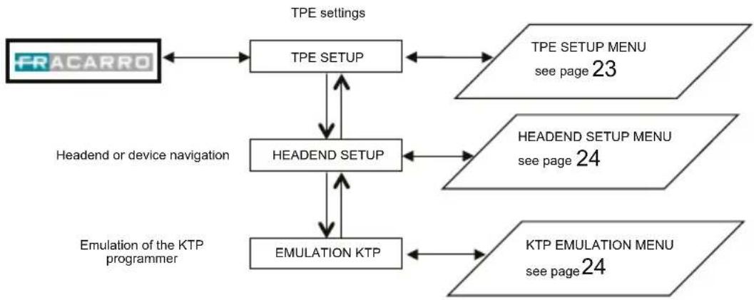
5.1.1 TPE GENERAL MENU
flowchart
graph TD
    A["FRACARRO"] --> B["TPE SETUP"]
    B --> C["HEADEND SETUP"]
    C --> D["EMULATION KTP"]
    D --> E["KTP EMULATION MENU see page 24"]
    B <--> F["TPE SETUP MENU see page 23"]
    C <--> G["HEADEND SETUP MENU see page 24"]
    D <--> H["Headend or device navigation"]
    H --> A
    style A fill:#f9f,stroke:#333
    style B fill:#ccf,stroke:#333
    style C fill:#cfc,stroke:#333
    style D fill:#fcc,stroke:#333
    style E fill:#cff,stroke:#333
    style F fill:#ffc,stroke:#333
    style G fill:#ffc,stroke:#333
    style H fill:#ffc,stroke:#333
Confirm the settings by pressing the √ key; save the settings by pressing the S key after the modules programmation.
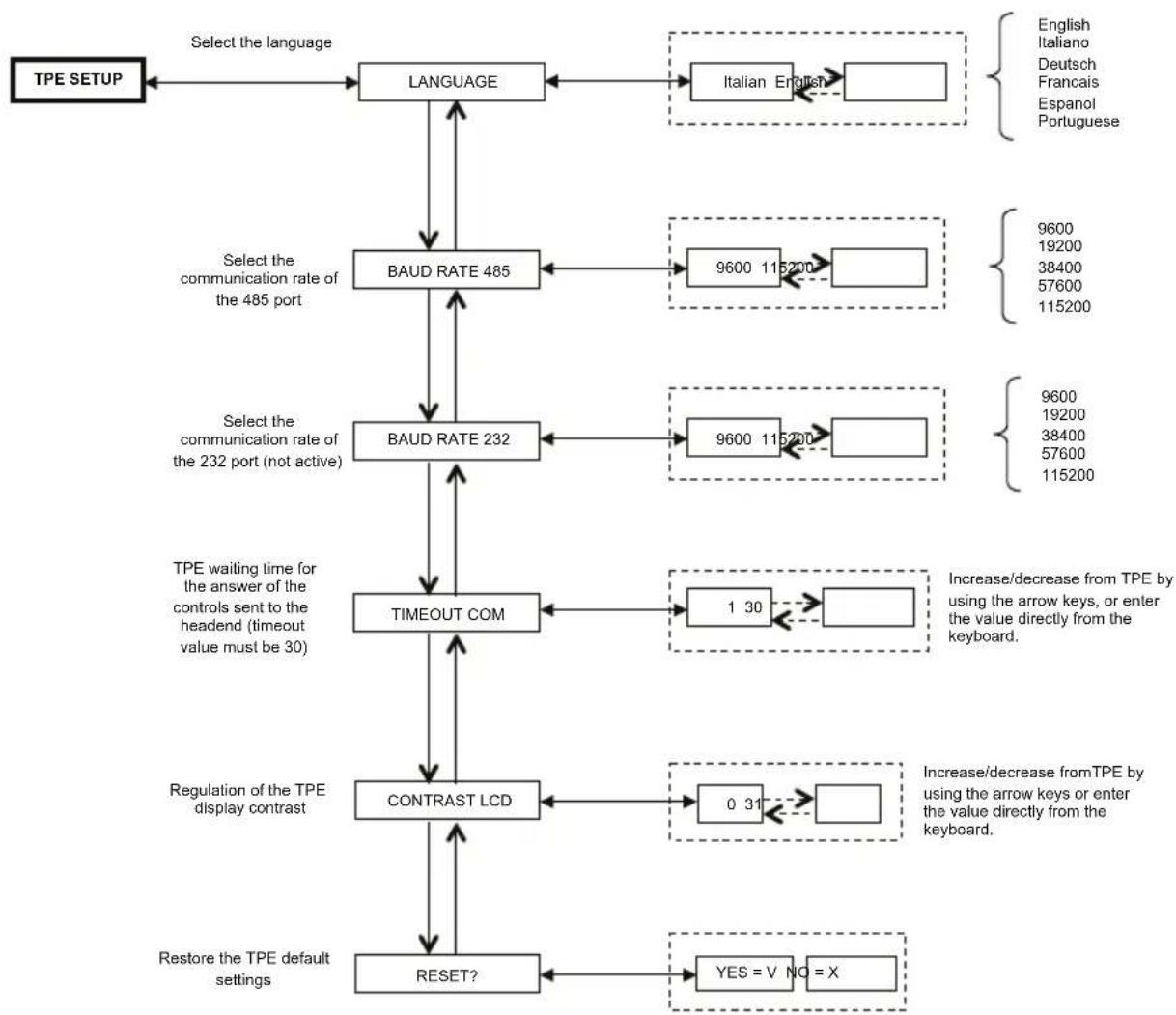
5.1.2 TPE SETUP MENU
flowchart
graph TD
    A["TPE SETUP"] --> B["LANGUAGE"]
    B --> C["BAUD RATE 485"]
    C --> D["BAUD RATE 232"]
    D --> E["TIMEOUT COM"]
    E --> F["CONTRAST LCD"]
    F --> G["RESET?"]
    G --> H["Restore the TPE default settings"]

    I["Select the language"] --> B
    J["Select the communication rate of the 485 port"] --> C
    K["Select the communication rate of the 232 port (not active)"] --> D
    L["TPE waiting time for the answer of the controls sent to the headend (timeout value must be 30)"] --> E

    M["English\nItaliano\nDeutsch\nFrancais\nEspanol\nPortuguese"] --> N["Italian English"]
    O["9600\n19200\n38400\n57600\n115200"] --> P["9600\n19200\n38400\n57600\n115200"]
    Q["1 30"] --> R["Increase/decrease from TPE by using the arrow keys, or enter the value directly from the keyboard."]
    S["0 31"] --> T["Increase/decrease from TPE by using the arrow keys or enter the value directly from the keyboard."]
    U["YES = V NO = X"] --> V["Yes = V NO = X"]
Confirm the settings by pressing the √ key; save the settings by pressing the S key after the modules programmation.
(The change of TPE language – confirmed by using S Key – perform a new mapping of the central modules)
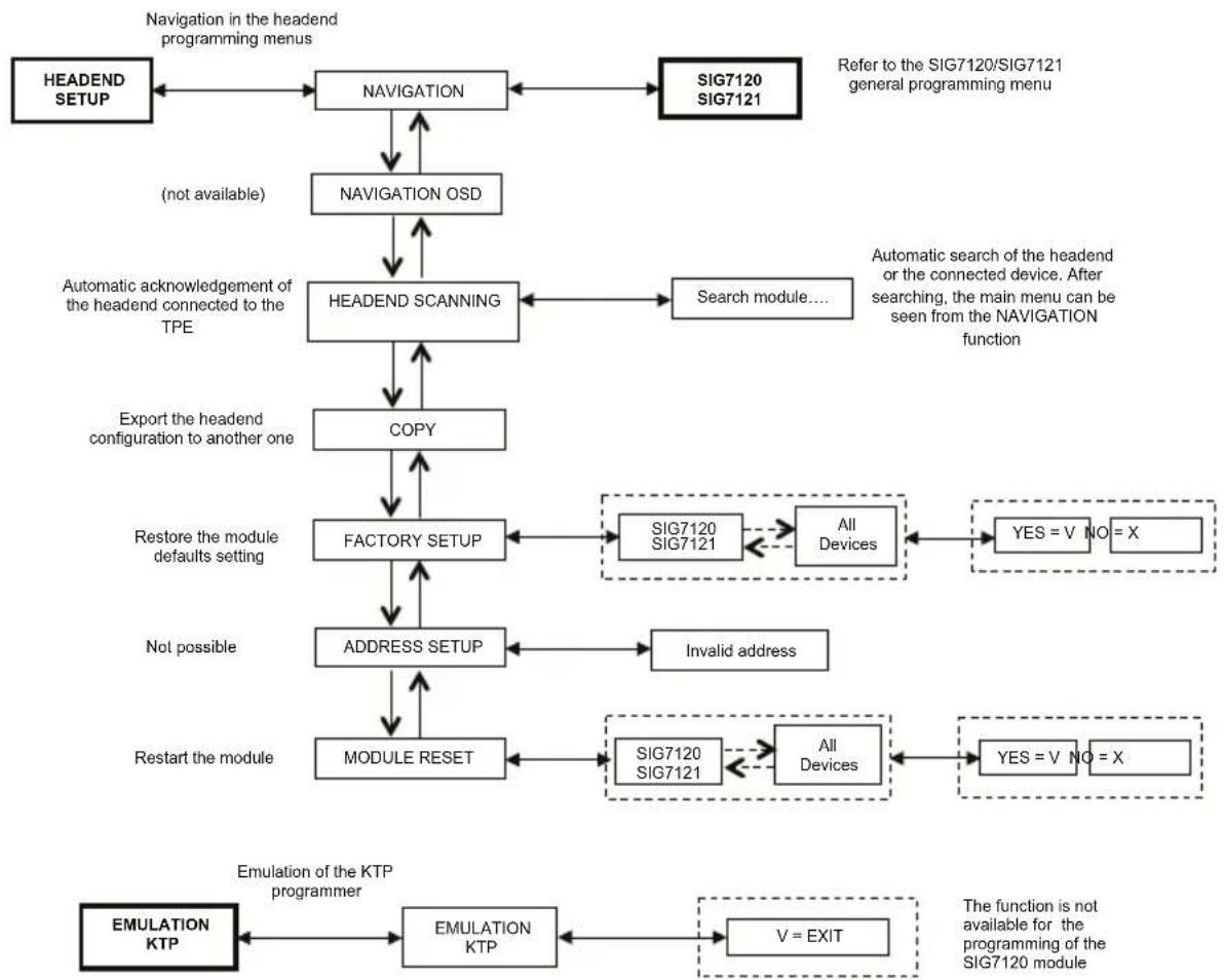
5.1.3 HEADEND SETUP AND EMULATION KTP MENU
flowchart
graph TD
    A["HEADEND SETUP"] --> B["NAVIGATION"]
    B --> C["NAVIGATION OSD"]
    C --> D["HEADEND SCANNING"]
    D --> E["COPY"]
    E --> F["FACTORY SETUP"]
    F --> G["ADDRESS SETUP"]
    G --> H["MODULE RESET"]
    H --> I["EMULATION KTP"]
    I --> J["EMULATION KTP"]
    J --> K["V = EXIT"]

    subgraph Navigation in the headend programming menus
        B
        C
        D
        E
        F
        G
        H
    end

    subgraph Referral to SIG7120/SIG7121 general programming menu
        B
        C
        D
        E
        F
        G
        H
    end

    subgraph Automatic acknowledgment of the headend connected to the TPE
        D
        E
        F
        G
        H
    end

    subgraph Automatic search of the headend or the connected device. After searching, main menu can be seen from the NAVIGATION function
        D
        E
        F
        G
        H
    end

    subgraph Export the headend configuration to another one
        E
        F
        G
        H
    end

    subgraph Restore the module defaults setting
        F
        G
        H
    end

    subgraph Not possible
        G
        H
    end

    subgraph Restart the module
        H
        I
    end

    subgraph EMulation of the KTP programmer
        J
        K
    end

    style Navigation fill:#f9f,stroke:#333
    style EW fill:#ccf,stroke:#333
Confirm the settings by pressing the √ key; save the settings by pressing the S key after the modules programmation.
NOTE: It is possible to modify the address only for the interconnection module SIG7900; after the modify it is necessary to scan the headend to update the addresses of all module in the rack, otherwise disconnect and reconnect the TPE from the headend to do the automatic scanning.
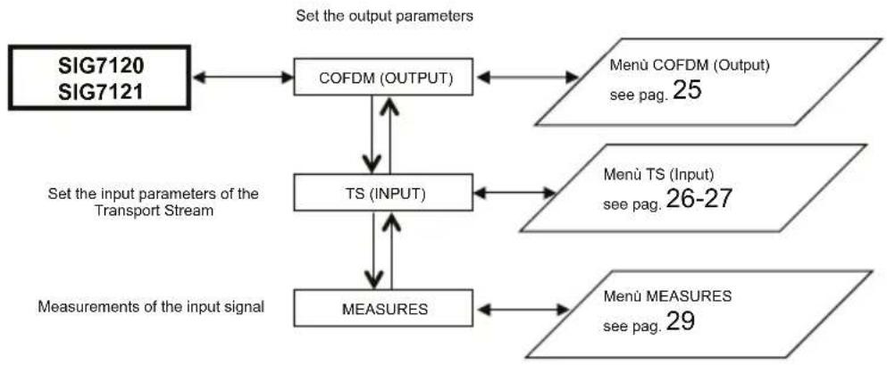
5.1.4 SIG7120 / SIG7121 GENERAL MENU
flowchart
graph TD
    A["SIG7120\nSIG7121"] --> B["COFDM (OUTPUT)"]
    B --> C["Menü COFDM (Output)\nsee pag. 25"]
    B --> D["TS (INPUT)"]
    D --> E["Menü TS (Input)\nsee pag. 26-27"]
    D --> F["MEASURES"]
    F --> G["Menü MEASURES\nsee pag. 29"]
    H["Set the input parameters of the Transport Stream"] --> D
    H --> F
    I["Measurements of the input signal"] --> F
Confirm the settings by pressing the √ key; save the settings by pressing the S key after the modules programmation.
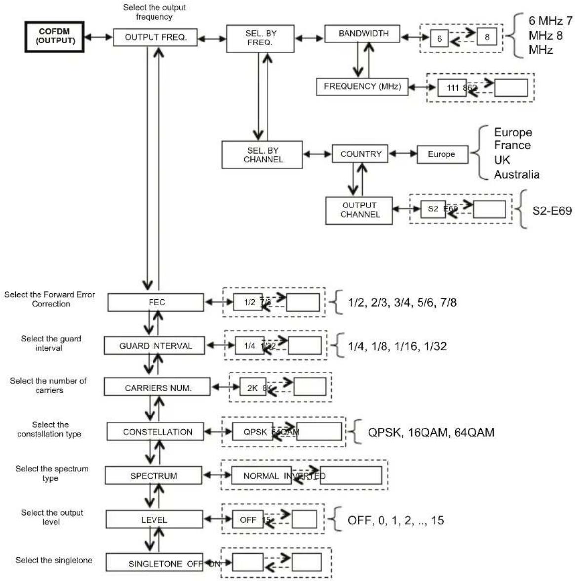
5.1.5 COFDM (OUTPUT) MENU
The following is the COFDM (OUTPUT) menu in detail:
flowchart
graph TD
    A["COFDM (OUTPUT)"] --> B["OUTPUT FREQ."]
    B --> C["SEL. BY FREQ."]
    C --> D["BANDWIDTH"]
    D --> E["6 MHz 7 MHz 8 MHz"]
    D --> F["FREQUENCY (MHz)"]
    F --> G["111 862"]
    G --> H["SELEC"]
    H --> I["COUNTRY"]
    I --> J["Europe"]
    J --> K["Output Channel"]
    K --> L["S2 E69"]
    L --> M["S2-E69"]
    C --> N["SEL. BY CHANNEL"]
    N --> O["FEC"]
    O --> P["1/2 7/8"]
    P --> Q["Select the Forward Error Correction"]
    Q --> R["GUARD INTERVAL"]
    R --> S["1/4 1/32"]
    S --> T["Select the number of carriers"]
    T --> U["CARRIERS NUM."]
    U --> V["2K 8K"]
    V --> W["Select the constellation type"]
    W --> X["CONSTELLATION"]
    X --> Y["QPSK 54QAM"]
    Y --> Z["QPSK, 16QAM, 64QAM"]
    X --> AA["SPECTRUM"]
    AA --> AB["NORMAL INVERTED"]
    AB --> AC["Select the spectrum type"]
    AC --> AD["LEVEL"]
    AD --> AE["OFF 15"]
    AE --> AF["Select the output level"]
    AF --> AG["SINGLESTONE OFF ON"]
    AG --> AH["OFF, 0, 1, 2, ..., 15"]
Confirm the settings by pressing the √ key; save the settings by pressing the S key after the modules programmation.
For the correct use, see paragraph 5.2 "INDICATIONS FOR PROGRAMMING".
OUTPUT FREQ. – sets the output frequency according to the channel (setting the country and the output channel) or according to the MHZ frequency (setting the bandwidth and the MHz frequency).
FEC – sets the parameter relevant to FEC (Forward Error Correction) among the possible choices (1/2, 2/3, 3/4, 5/6, 7/8).
GUARD INTERVAL – sets the guard interval among the possible choices (1/4, 1/8, 1/16, 1/32).
CARRIERS NUM. – sets the number of carriers between 2K and 8K.
CONSTELLATION – sets the constellation, QPSK, 16QAM or 64QAM, with which the carriers are modulated.
SPECTRUM – regulates the spectrum as NORMAL or REVERSED according to the reception instrument that might work only in one of the two modes. Usually the “NORMAL SPECTRUM” setting is used.
LEVEL – regulates the output level on a scale between 0 and 15 to which a STEP equal to 1dB corresponds. Setting the level to OFF, the output signal is disabled. The OFF output level can be set only during the normal operation and not when the SINGLETONE function is activated.
SINGLE TONE – allows the use of a single tone at the input to facilitate the measurement of the output level. When the SINGLE TONE function is activated, no other channels can be inserted.
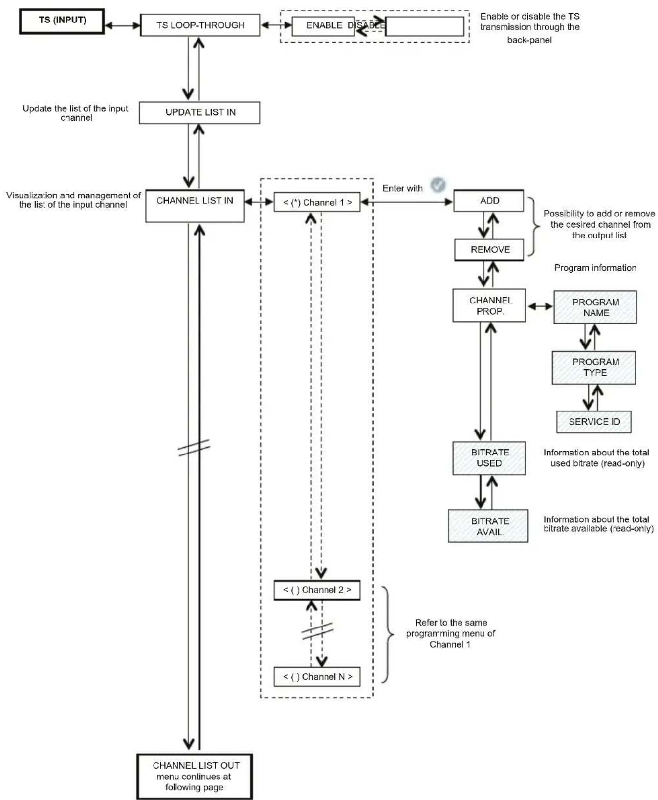
5.1.6 TS (INPUT) MENU
The TS (INPUT) menu allows one to program the channel list that the modulator receives and distributes from the transport stream. The TS (INPUT) menu is shown in detail:
flowchart
graph TD
    A["TS (INPUT)"] --> B["TS LOOP-THROUGH"]
    B --> C["UPDATE LIST IN"]
    C --> D["CHANNEL LIST IN"]
    D --> E["<<(*) Channel 1>>"]
    E --> F["ADD"]
    F --> G["REMOVE"]
    G --> H["CHANNEL PROP."]
    H --> I["BITRATE USED"]
    I --> J["BITRATE AVAIL."]
    J --> K["PROGRAM NAME"]
    K --> L["PROGRAM TYPE"]
    L --> M["SERVICE ID"]
    M --> N["Information about the total used bitrate (read-only)"]
    N --> O["Information about the total bitrate available (read-only)"]
    O --> P["Refer to the same programming menu of Channel 1"]
    P --> Q["<<() Channel 2>>"]
    Q --> R["< () Channel N >"]
    R --> S["CHANNEL LIST OUT menu continues at following page"]
    style A fill:#f9f,stroke:#333
    style D fill:#ccf,stroke:#333
    style F fill:#cfc,stroke:#333
    style H fill:#fcc,stroke:#333
    style I fill:#cff,stroke:#333
    style J fill:#ffc,stroke:#333
    style K fill:#fcf,stroke:#333
    style L fill:#fcf,stroke:#333
    style M fill:#fcf,stroke:#333
    style N fill:#cff,stroke:#333
    style O fill:#cff,stroke:#333
    style P fill:#ffc,stroke:#333
Confirm the settings by pressing the √ key; save the settings by pressing the S key after the modules programmation.
flowchart
graph TD
    A["Continuation from CHANNEL LIST IN menu"] --> B["CHANNEL LIST OUT"]
    B --> C["< () Channel 1 >"]
    C --> D["POSITION"]
    D --> E["1/X"] --> F["X/X"]
    D --> G["REMOVE"]
    G --> H["LCN CONF."]
    H --> I["Disable"] --> J["Enable"]
    I --> K["LCN SET"]
    K --> L["0"] --> M["1000"]
    L --> N["0 - 999 LCN 1000 Disable"]
    C --> O["< () Channel 2 >"]
    O --> P["< () Channel N >"]
    P --> Q["Clear the output channel list"]
    Q --> R["CLEAR LIST OUT"]
    R --> S["PID MANAGEMENT"]
    S --> T["ADD PID"]
    T --> U["ADDED PID LIST"]
    U --> V["ADDED PID LIST < -->"]
    V --> W["CUT PID"]
    W --> X["Scroll PID list by using TPE arrows"]
    T --> Y["Remove PID menu"]
    Y --> Z["REMOVE PID"]
    Z --> AA["CUT PID LIST"]
    AA --> AB["CUT PID LIST < xxx >"]
    AB --> AC["RESTORE PID"]
    S --> AD["Show Added PID list"]
    AD --> AE["Show the Cut PID list"]
    AE --> AF["Clear the Added PIDs from the list"]
    AF --> AG["Clear ADDED PIDs"]
    AG --> AH["RESTORE CUT PIDs"]
    AH --> AI["TS source selection (back panel or ASI connector) Available only for SIG7121"]
    AI --> AJ["TS IN SELECTION"]
    AJ --> AK["ALL PIDs OUT"]
    AK --> AL["Advanced CONFIG menu continues at following page"]

    subgraph Details
        direction TB
        direction LR
        note1["Enter with"]
        note2["Refer to the same programming menu of Channel 1"]
        note3["Insert value directly from TPE numeric keyboard."]
        note4["Insert value directly from TPE numeric keyboard."]
        note5["Insert value directly from TPE numeric keyboard."]
        note6["Insert value directly from TPE numeric keyboard."]
        note7["Insert value directly from TPE numeric keyboard."]
        note8["Insert value directly from TPE numeric keyboard."]
        note9["Insert value directly from TPE numeric keyboard."]
        note10["Insert value directly from TPE numeric keyboard."]
        note11["Insert value directly from TPE numeric keyboard."]
        note12["Insert value directly from TPE numeric keyboard."]
        note13["Insert value directly from TPE numeric keyboard."]
        note14["Insert value directly from TPE numeric keyboard."]
        note15["Insert value directly from TPE numeric keyboard."]
        note16["Insert value directly from TPE numeric keyboard."]
        note17["Insert value directly from TPE numeric keyboard."]
        note18["Insert value directly from TPE numeric keyboard."]
        note19["Insert value directly from TPE numeric keyboard."]
        note20["Insert value directly from TPE numeric keyboard."]
        note21["Insert value directly from TPE numeric keyboard."]
        note22["Insert value directly from TPE numeric keyboard."]
        note23["Insert value directly from TPE numeric keyboard."]
        note24["Insert value directly from TPE numeric keyboard."]
        note25["Insert value directly from TPE numeric keyboard."]
        note26["Insert value directly from TPE numeric keyboard."]
        note27["Insert value directly from TPE numeric keyboard."]
        note28["Insert value directly from TPE numeric keyboard."]
        note29["Insert value directly from TPE numeric keyboard."]
        note30["Insert value directly from TPE numeric keyboard."]
        note31["Insert value directly from TPE numeric keyboard."]
        note32["Insert value directly from TPE numeric keyboard."]
        note33["Insert value directly from TPE numeric keyboard."]
        note34["Insert value directly from TPE numeric keyboard."]
        note35["Insert value directly from TPE numeric keyboard."]
        note36["Insert value directly from TPE numeric keyboard."]
        note37["Insert value directly from TPE numeric keyboard."]
        note38["Insert value directly from TPE numeric keyboard."]
        note39["Insert value directly from TPE numeric keyboard."]
        note40["Insert value directly from TPE numeric keyboard."]
        note41["Insert value directly from TPE numeric keyboard."]
        note42["Insert value directly from TPE numeric keyboard."]
        note43["Insert value directly from TPE numeric keyboard."]
        note44["Insert value directly from TPE numeric keyboard."]
        note45["Insert value directly from TPE numeric keyboard."]
        note46["Insert value directly from TPE numeric keyboard."]
        note47["Insert value directly from TPE numeric keyboard."]
        note48["Insert value directly from TPE numeric keyboard."]
        note49["Insert value directly from TPE numeric keyboard."]
        note50["Insert value directly from TPE numeric keyboard."]
        note51["Insert value directly from TPE numeric keyboard."]
        note52["Insert value directly from TPE numeric keyboard."]
        note53["Insert value directly from TPE numeric keyboard."]
        note54["Insert value directly from TPE numeric keyboard."]
        note55["Insert value directly from TPE numeric keyboard."]
        note56["Insert value directly from TPE numeric keyboard."]
        note57["Insert value directly from TPE numeric keyboard."]
        note58["Insert value directly from TPE numeric keyboard."]
        note59["Insert value directly from TPE numeric keyboard."]
        note60["Insert value directly from TPE numeric keyboard."]
        note61["Insert value directly from TPE numeric keyboard."]
        note62["Insert value directly from TPE numeric keyboard."]
        note63["Insert value directly from TPE numeric keyboard."]
        note64["Insert value directly from TPE numeric keyboard."]
        note65["Insert value directly from TPE numeric keyboard."]
        note66["Insert value directly from TPE numeric keyboard."]
        note67["Insert value directly from TPE numeric keyboard."]
        note68["Insert value directly from TPE numeric keyboard."]
        note69["Insert value directly from TPE numeric keyboard."]
        note70["Insert value directly from TPE numeric keyboard."]
        note71["Insert value directly from TPE numeric keyboard."]
        note72["Insert value directly from TPE numeric keyboard."]
        note73["Insert value directly from TPE numeric keyboard."]
        note74["Insert value directly from TPE numeric keyboard."]
        note75["Insert value directly from TPE numeric keyboard."]
        note76["Insert value directly from TPE numeric keyboard."]
        note77["Insert value directly from TPE numeric keyboard."]
        note78["Insert value directly from TPE numeric keyboard."]
        note79["Insert value directly from TPE numeric keyboard."]
        note80["Insert value directly from TPE numeric keyboard."]
        note81["Insert value directly from TPE numeric keyboard."]
        note82["Insert value directly from TPE numeric keyboard."]
        note83["Insert value directly from TPE numeric keyboard."]
        note84["Insert value directly from TPE numeric keyboard."]
        note85["Insert value directly from TPE numeric keyboard."]
        note86["Insert value directly from TPE numeric keyboard."]
        note87["Insert value directly from TPE numeric keyboard."]
        note88["Insert value directly from TPE numeric keyboard."]
        note89["Insert value directly from TPE numeric keyboard."]
        note90["Insert value directly from TPE numeric keyboard."]
        note91["Insert value directly from TPE numeric keyboard."]
        note92["Insert value directly from TPE numeric keyboard."]
        note93["Insert value directly from TPE numeric keyboard."]
        note94["Insert value directly from TPE numeric keyboard."]
        note95["Insert value directly from TPE numeric keyboard."]
        note96["Insert value directly from TPE numeric keyboard."]
        note97["Insert value directly from TPE numeric keyboard."]
        note98["Insert value directly from TPE numeric keyboard."]
        note99["Insert value directly from TPE numeric keyboard."]
        note100["Insert value directly from TPE numeric keyboard."]
    end
flowchart
graph TD
    A["Continuation from ALL PIDs OUT menu"] --> B["ADVANCED CONFIG"]
    B --> C["SET ONID"]
    C --> D["0 65535"]
    D --> E["Increase/decrease from TPE by using the arrow keys, or enter the value directly from the keyboard."]
    C --> F["SET TS ID"]
    F --> G["0 65535"]
    G --> H["Increase/decrease from TPE by using the arrow keys, or enter the value directly from the keyboard."]
    F --> I["HEADEND DECRYPT."]
    I --> J["ON OFF"]
    J --> K["Enable/Disable signal properties (coded flag)."]
    style A fill:#f9f,stroke:#333
    style B fill:#ccf,stroke:#333
    style C fill:#cfc,stroke:#333
    style D fill:#fcc,stroke:#333
    style E fill:#cff,stroke:#333
    style F fill:#ffc,stroke:#333
    style G fill:#ffc,stroke:#333
    style H fill:#ffc,stroke:#333
    style I fill:#cfc,stroke:#333
    style J fill:#fcc,stroke:#333
    style K fill:#cfc,stroke:#333
Confirm the settings by pressing the √ key; save the settings by pressing the S key after the modules programmation.
TS LOOP-THROUGH – it is possible to use this control to enable or disable the distribution to adjacent modules from the transport stream on the back-panel. By disabling the loop-through TS in the first modulator, the content reception of the module itself is not affected, but the reception in the following modulators is interrupted.
UPDATE LIST IN – updates the channel list from the digital receiver input.
IMPORTANT: the modulator automatically update the input channel list; therefore, a manual update must be carried out after modifying the reception settings of the receiver module or after activating the loop-through TS in the modulator before it.
Do the manual updating after enabling the loop-through TS in the module before it.
CHANNEL LIST IN – displays the list of channels present at the transport stream input. For every list channel the submenus are the following::
- ADD: adds the selected channel to the list of channels to be distributed at the output;
- REMOVE: removes the selected channel from the list of channels to be distributed at the output;
- CHANNEL PROP. : provides information about the properties of the channels in the input list. The following submenus are available:
• PROGRAM NAME: provides the program name
• PROGRAM TYPE: provides information on the program type
• SERVICE ID: provides information on the service identification code.
- BITRATE USED: provides information about the used bitrate. This parameter refers to the total measurement of all channels added to the output channel list.
- BITRATE AVAIL. : provides information of the available bitrate. This parameter refers to the total measurement of the available bitrate at the output after inserting one or more channels.
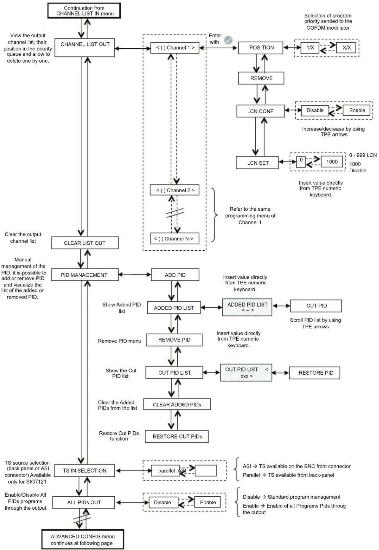
CHANNEL LIST OUT – displays the output channel list selected from the list of available channels at the input. For every list channel the submenus are the following:
- POSITION: shows the position occupied by the selected channel in the priority queue of output channels (see paragraph 5.2),
- REMOVE: removes a single selected channel from the output channel list; in particular, if there are channels from previous settings, this control is an alternative to setting the whole channel list to zero.
• LCN CONF: enable/disable LCN (Logical Channel Number) function for selected program;
• LCN SET: set the LCN number for selected program
CLEAR LIST OUT – completely sets the output channel list to zero.
PID MANAGEMENT – manages the available services; it is useful in particular distribution conditions. The following can be set:
- ADD PID: adds a program's PID (it is possible to add maximum 10 PIDs)
• ADDED PID LIST: displays the list of the PIDs added during programming
- REMOVE PID: removes only the selected PID
- REMOVE PID: removes/disables a PID by setting it from the TPE keyboard
• CUT PID LIST: to display the list of the removed/disabled PIDs
- RESTORE PID: manually restores the previously selected removed/disabled PID
- CLEAR ADDED PIDs: sets all the previously added PIDs to zero with a single operation.
• RESTORE CUT PIDs: restores all the previously removed/disabled PIDs with a single operation.
TS IN SELECTION – Parallel (back-panel) or Serial (ASI) Transport Stream selection source;
ALL PIDs OUT – send to the output all the PIDs (programs) contained on the Transport Stream Input (up to 32 PIDs maximum);
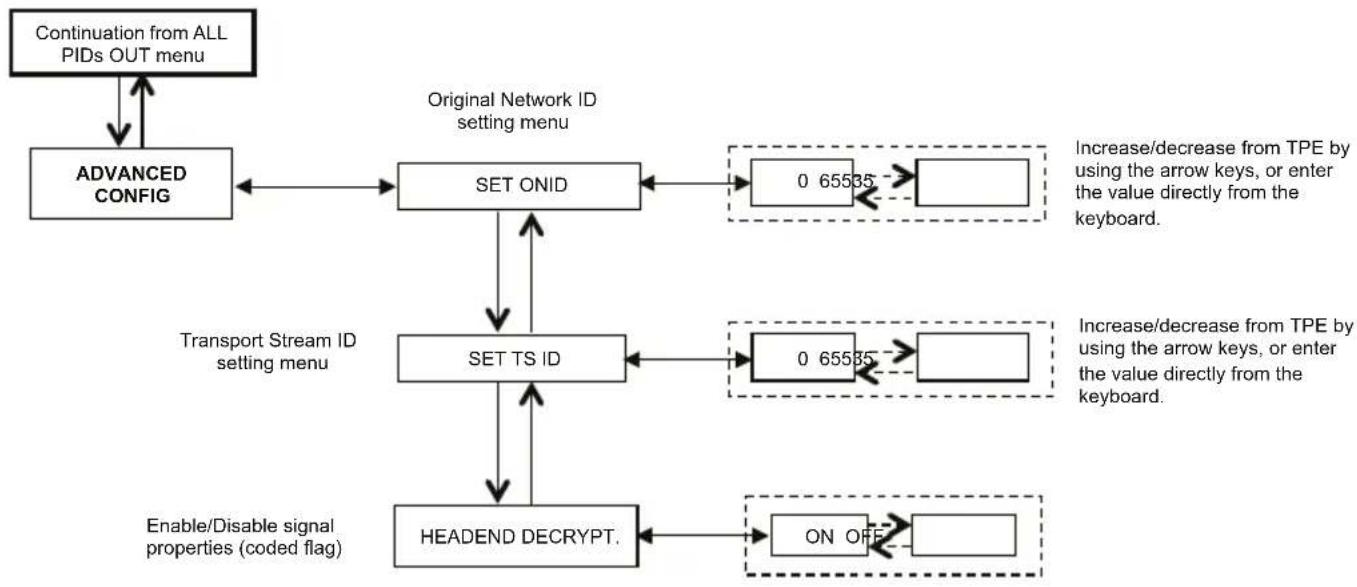
ADVANCED MANAGEMENT
Advanced management configuration of the individual parameters involved in the transponder or program was provided to overcome any deficiencies related to obsolescence or incomplete management of certain parameters by the set top box connected to the outlet
• SET ORIG. Net ID: You can manually change the Network ID used originally set by the broadcaster:
- Set TS ID: You can manually change the ID associated to the Transport Stream originally set by the broadcaster;
- HEADEND Decrypt: you can change the status (ON / OFF) of the flag on the program decoded into central prevents the OSD message "encoded image" is being revived in the TV overlay or Set Top Box connected to the outlet.
NOTE: the addition or the removal of the PIDs does not imply the regeneration of the program tables.
flowchart
graph TD
    A["MEASURES"] --> B["SOFTWARE VERS."]
    B --> C["BITRATE"]
    C --> D["BITRATE USED"]
    D --> E["BITRATE AVAIL."]
    E --> F["BR. USED PEAK"]
    F --> G["BR. AVAIL. PEAK"]
    G --> H["RESET BR. PEAKS"]
    H --> I["OVERFLOW ALARM"]
    I --> J["RESET ALARM"]
    J --> K["TEMP. MOD. CORE"]
    K --> L["NORMAL"]
    L --> M["OVERTEMP ALARM"]
    M --> N["RESET ALARM"]
    N --> O["Information about temperature"]
    C --> P["Information about bitrate of transmitted channel"]
    D --> Q["Measurement of used bitrate"]
    E --> R["Measurement of available bitrate"]
    F --> S["Measurement of the peak of used bitrate"]
    G --> T["Measurement of the peak of available bitrate"]
    H --> U["Reset of the bitrate peaks"]
    I --> V["Read only"]
    K --> W["Read only"]
Confirm the settings by pressing the √ key; save the settings by pressing the S key after the modules programmation.
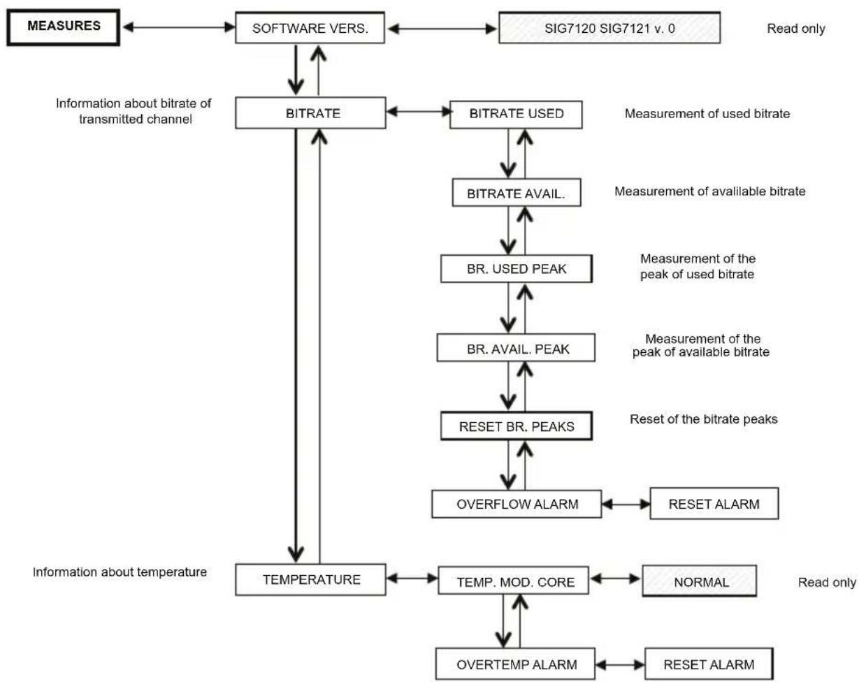
5.1.7 MEASURES MENU
By means of the MEASURES TPE menu, it is possible to display some information about the bitrate and the module temperature. The available menus are as follows:
SOFTWARE VERS. – in one reading, it provides the software version installed on the module.
BITRATE – allows one to know the measurements carried out on the bitrate of the multiplex of output channels. In particular, it allows one to display:
- BITRATE USED, provides a measurement in bit/s of the bitrate totally used by the channels present in the output multiplex,
- BITRATE AVAIL., provides a measurement in bit/s of the total available bitrate in the output multiplex with inserted channels,
- BR. USED PEAK, provides a measurement in bit/s of the peak of maximum bitrate used by the channels present in the output multiplex,
• BR. AVAIL.PEAK, provides a measurement in bit/s of the total available bitrate peak in the output multiplex, - RESET BR. PEAKS, resets the peaks to the initial values calculated according to the COFDM modulation settings. This function should be used after a bitrate overflow, after which the peaks have reached their limit value,
- OVERFLOW ALARM indicates if a bitrate overflow has taken place. In particular, if this flag is ON, an alarm took place, whilst the flag is OFF in normal functioning operations. By cancelling the overflow alarm, the module is taken back to the standard operational conditions (the red LED is switched OFF).
TEMPERATURE – allows one to know all the conditions of the module's internal temperature, that is:
- TEMP. MOD.CORE, in read-only mode, provides direction about the module's functioning zone. There are two operation thresholds and three operation zones:
• NORMAL: no alarm indication;
• HIGH: the red LED flashes rapidly to indicate an anomaly, but the module continues operating properly;
- CRITICAL: the red LED is on and the module is switched off. After switching it off, with regular intervals of about 10 minutes, the module is switched on again and the temperature is rechecked.
- OVERTEMP. ALARM, provides an indication of the temperature alarm event. If you enter the critical temperature zone, an alarm flag is set in this submenu. It signals the temperature alarm event. This flag can be reset only by the TPE; after resetting the flag, the red LED switches off.
5.2 INDICATIONS FOR PROGRAMMING
NOTE: Before proceeding with the programming of the module you should follow these general guidelines
- decide if you want to use the ALL PID OUT or individually programmed programs (PID) which should be available in output; in ALL PID OUT set status most utilities will be disabled (i.e. LCN management, Overflow management, single PID management, etc)
- decide if you want to use Back-panel TS (parallel) or ASI serial TS (only for SIG7121 module);
- for individual PID program available to the output, please follow the indication below.
Programming and setting the modulation parameters of the New Headline module must be carried out carefully in the following mode. In particular, the total bitrate of the output programs must be lower than the maximum threshold defined by the COFDM modulation parameters. Pay attention to the ALL PID OUT selection: if the total bitrate of the output programs overcomes the accepted bitrate, the module generates a bitrate overflow event. In ALL PID OUT status selection it should risk failure in the showed video programs (scramble effect on low priority programs).
To know the maximum available bitrate, refer to the following tables where the bitrate values in bit/s are shown according to a few COFDM modulation parameters (constellation, FEC, guard interval). The shown measures refer to an output bandwidth equal to 8 MHz. The values will be lower if a width of 6 MHz or 7 MHz is set.
| Constellation: QPSK | |||||
| Guard Interval | |||||
| FEC | 1/4 1/8 | 1/16 1/32 | |||
| 1/2 4.976 | 5.52 | 8 5.855 | 6.032 | ||
| 2/3 6.637 | 7.37 | 2 7.807 | 8.043 | ||
| 3/4 7.464 | 8.29 | 4 8.782 | 9.050 | ||
| 5/6 8.294 | 9.21 | 6 9.756 | 10.053 | ||
| 7/8 8.706 | 9.67 | 4 10.246 | 10.554 | ||
| Constellation: 16QAM | |||||
| Guard Interval | |||||
| FEC | 1/4 1/8 | 1/16 1/32 | |||
| 1/2 9.952 | 11.0 | 57 11.7 | 1 12.064 | ||
| 2/3 13.271 | 14 | 745 15.6 | 12 16.086 | ||
| 3/4 14.928 | 16 | 589 17.5 | 64 18.093 | ||
| 5/6 16.589 | 18 | 430 19.5 | 16 20.104 | ||
| 7/8 17.416 | 19 | 352 20.4 | 90 21.114 | ||
| Constellation: 64QAM | |||||
| Guard Interval | |||||
| FEC | 1/4 1/8 | 1/16 1/32 | |||
| 1/2 14.928 | 16.589 | 17.564 | 18.093 | ||
| 2/3 19.905 | 22.118 | 23.416 | 24.126 | ||
| 3/4 22.393 | 24.881 | 26.346 | 27.143 | ||
| 5/6 24.881 | 27.647 | 29.272 | 30.161 | ||
| 7/8 26.123 | 29.027 | 30.737 | 31.669 | ||
The various COFDM modulation parameters (number of carriers, constellation, FEC, guard interval) can be set by the installer to make the system more efficient in critical installation conditions (for example lack of spurious, several adjacent channels, transmission with errors,...).
IMPORTANT: in standard installation diagrams, we recommend keeping the COFDM modulation settings with the default values (64-QAM constellation, 7/8 FEC, 1/32 guard interval). How you can see in the tables above, the default settings guarantee a wider bandwidth.
The modulator programming must be done in order to make it as insensitive as possible to an increase of a bitrate of one or more programs inserted queue in the output multiplex. The multiplex of the output programs is organized according to a Last In First Out priority: the last inserted program in the queue is the first program to be removed if it exceeds the maximum available bitrate threshold. The program's position in the list can be modified at any moment through the proper TPE menu.
In the event of an overflow alarm, the module continues operating correctly by eliminating one or more programs, starting with the one that has a lower priority (the first inserted program is the most protected one).
NOTE: carry out a complete reset of the output channel list before inserting other channels.
It is fundamental to distinguish the programming into two typologies according to the transmission mode of the programs to be distributed, which means in the case of a transmission with a static bitrate (A) or a dynamic bitrate (B). We recommend referring to the statistics provided by web sources before, alternatively (but this solution may not be sufficient), monitoring the bitrate measurements provided by the TPE for a few minutes.
A. In the event of channels transmitted with static bitrate (generally channels with standard definition - SD), programming should be done as follows:
- reset the bitrate peaks from the TPE menu,
- check the setting of the modulation parameters,
- insert the programs in the output multiplex one at a time by inserting the measurement reading of the used bitrate;
- after inserting all the desired programs, make sure that the measurement of the used bitrate peak (available from the TPE MEASUREMENTS menu) does not exceed the maximum available limit.
IMPORTANT: pay attention not to exceed the threshold of the maximum bitrate that varies according to the set modulation parameters according to the tables shown before. In the event that the overflow event takes place, the red LED in the front panel of the module flashes rapidly and an alarm FLAG is set in the TPE. This alarm can be displayed and reset from the MEASUREMENTS menu of the programmer. Furthermore, one or more programs
are removed, starting from the one with the lowest priority. If one or more PIDs have been added manually, the first action will be to remove them.
IMPORTANT: to make the module insensitive to possible bitrate peaks, leave a rather large gap after having monitored the peaks (approx. at least 1 free Mbit/s per each inserted channel).
B. In the event of channels being transmitted with a dynamic bitrate (generally high definition channels - HD), the multiplex programming is different from the previous case. Before inserting a program, it is necessary to have the bitrate that the channel is transmitted with. Then do the following:
- reset the bitrate peaks from the TPE menu,
- check the setting of the modulation parameters,
- insert, as first program, the program with a dynamic bitrate that you want to preserve from a possible overflow of bitrate,
- monitor the used bitrate's peak measurement for at least 1 minute by means of the proper TPE menu,
- make sure that the value of the remaining available bitrate is enough to allow the insertion of other programs,
- check the presence of programs with a static bitrate in the same transponder,
- insert the programs, one after another, in the output multiplex by checking the used and available bitrate carefully after each insertion,
- make sure that the bandwidth is sufficient to keep the modulator immune from possible bitrate peaks due to the program inserted with dynamic bitrate (remember that high definition programs transmitted with variable bitrate can have transmission peaks of up to 20 Mbit/s *),
IMPORTANT: To keep the system immune from bitrate overflow, keep the bitrate lower than the maximum threshold defined according to the used modulation settings (refer to the tables shown before). Remember that the high definition programs transmitted with dynamic bitrate can have transmission peaks of up to 20 Mbit/s; therefore, the installer must make sure to have monitored the bitrate peaks carefully during the programming as well as get informed about the transmission modes of the channels to be distributed.
NOTE: we recommend disabling the Transport Stream loop-through in the last installed modulator.
* The indicated values refer to the current transmission conditions of the channel in SD and HD. Changes are possible due to the technological development.
6. FIRMWARE UPDATING INSTRUCTIONS
To update the firmware of the modules, refer to the download section of our Internet web site www.fracarro.com.
ATTENTION: Updating the firmware on the module could last about 20 minutes in certain cases. The power must be disconnected from the module during updating; otherwise, take the module to the FRACARRO Technical Service Centre.
7. TROUBLESHOOTING
The following is a summarizing table of a few useful suggestions for the diagnosis and solution of possible module problems.
| Problem Explanation Solution | ||
| Red LED on (not in start-up phase) | General malfunctioning | Contact Fracarro TECHNICAL ASSISTANCE |
| TPE does not identify the module while navigating in the headend | Headend navigation while the module is in the initialization phase | The modulator needs about 30 seconds to be initialized. Wait for the initialization to be completed before doing the headend scanning. Disconnect and reconnect the TPE or do the scanning again. |
| Not available channel list | Wrong updating of the input channel list | Carry out the manual update of the channel list by means of the proper TPE menu. Make sure that the TS-loop through is enabled in the previous modules modules or verify the correct selection of the TS (ASI or back-panel) |
| In the output channel list, all the channels set haven't been set before | The maximum limit of available bitrate was exceeded and an overflow alarm took place (the red LED flashes rapidly) | Reset the overflow alarm flag and, before continuing with the programming, check, from the output channel list, which channel caused the alarm. |
| It's impossible to insert another program in the output channel list. | The maximum number of channels supported by the module was reached | The maximum number of channels is 32. Eliminate as many channels as you want from the output channel list and add other channels |
| In the output channel list, there are channels that are not present in the transponder you are locked to | In the output channel list, a few channels are memorized from previous installations | Reset the output channel list before performing any new programming |
| After a firmware update, the module does not work | The firmware update can last even 20 minutes | If the power supply was interrupted during the upgrade of the module firmware, contact FRACARRO technical assistance to update the module |
| The headend scanning by the TPE does not detect any module | Temporary absence of communication between the module and the sub-rack | Disconnect and reconnect the TPE or do a new headend scanning |
| You can not enter the module navigation menu when utilizing the TPE. | If the green LED is rapidly flashing and the red LED is OFF, the module is updating the channel list. | Wait for about 10 seconds and then enter the navigation menu again. |
- TECHNICAL SPECIFICATIONS
| TRANSPORT STREAM INPUT | |
| Connector 48 poles on the back panel or 75Ω BNC front | |
| Typology Parallel (8 data bits, clock e datavalid) o | Serial (ASI - only for SIG7121) |
| Maximum bitrate 100 Mbit/s (parallel, back-panel) o 270Mbit/s (serial on BNC - only for SIG7121) | |
| Level TTL | |
| TS flow Continuous mode or burst | |
| Programs SD o HD, FTA o CA, MPEG2 o H264 | |
| FILTERING AND MULTIPLEXING PID | |
| Selection by means of the TPE of the programs that should be remodulated | |
| Regeneration of the DVB-T table | |
| Multiplexing of the DVB-T | |
| PCR restamping, LCN management | |
| OUTPUT SIGNAL | |
| Connectors F TYPE, FEMALE | |
| Frequency range 111 ÷ 862 MHz | |
| Channels S2 ÷ E69 | |
| Frequency step 10 KHz | |
| Frequency precision < 25 KHz | |
| Maximum output level 85 ± 2 dBμV | |
| Channel flatness < ±1dB | |
| Level adjustment 0 ÷ 15dB (programmable 1dB step) | |
| Loop-through loss | < 1.5 dB |
| Return Loss | >10 dB |
| Modulation type | DVB-T (ETSI EN 300 744) |
| Channel bandwidth | 6, 7, 8 MHz |
| Carriers | 2K, 8K |
| Constellations | QPSK, 16QAM, 64QAM |
| FEC | 1/2, 2/3, 3/4, 5/6, 7/8 |
| Guard interval | 1/4, 1/8, 1/16, 1/32 |
| Spectrum Normal, reverse | |
| Output MER | >34 dB |
| Spurious level | ≥ 50 dB |
| GENERAL | |
| Operational temperature | -10 ÷ 45°C |
| Back panel connection | 220 VAC, RS485, ADDRESSES LINE, TS |
| Power supply tension | 184 ÷ 264VAC, 50÷60Hz, CLASS II |
| Maximum consumption | 10 W |
Technical data is nominal values and refer to an operating temperature of 25^ C.
ATTACHMENT - GLOSSARY
ASI - Asynchronous Serial Interface - The DVB Asynchronous Serial Interface (ASI) is a very popular standard interface for conveying MPEG-2 transport streams between professional equipment.
BITRATE - The bitrate is the measurement of signal's transmission rate; it is calculated according to the bit per second (bps). The multiples are Kbps (1.024 bps), Mbps (1.024 Kbps) and Gbps (1.024 Mbps).
COFDM (Coded Orthogonal Frequency Division Multiplexing) - A modulation diagram that shares the digital signals on more simultaneous carriers. Then the signals are orthogonally sent, one to another, in order to avoid interferences. It is used in Europe by the DVB-T standard.
CONSTELLATION - Representation with the I/Q coordinates of the phase and amplitude status that a QAM or QPSK modulated digital carrier can take.
FEC - Forward Error Correction - A technique to correct the errors during the reception phase. It is obtained by adding a known redundancy during transmission. The code rate is indicated like a ratio between the signal part used for services and the total part of the available signal. For example, a FEC of 2/3 indicates that 2/3 is the available part for services whilst 1/3 of the signal is devoted to the correction code.
GUARD INTERVAL - To avoid echoes generated by the transmitter itself, or echoes coming from other transmitters belonging to the same network, a guard interval is inserted between two consecutive symbols.
MPEG (Motion Picture Experts Group) - International committee for the standardization of the codification, compression, transmission and recording of images and sound. The compression consists of the elimination of a few data coming from the signal digitalization; the compression is not perceived by human eyes and ears.
- MPEG-1 is the audio and video optimized compression to be used for low quality applications.
- MPEG-2 is used for high quality television applications.
- MPEG-4 uses a more efficient compression algorithm and allows, differently from a MPEG-2, a higher reduction of the bitrate without significant losses in quality.
OVERFLOW - It is used when a digital memory (for example a buffer) is loaded over its capacity to keep data. The excess data are lost or, even worse, affect the functioning.
PES - Packetized Elementary Stream - It is the digital data packet relevant to a program's audio-video-data information.
PID - Packet Identifier - Number of 13 bits contained in the TS (Transport Stream) that allows one to identify if a TS packet belongs to a PES. The choice of program is carried out by the insertion of the relevant video and audio PIDs; a specific information flow is associated to each PID.
PILOT CARRIER - In the COFDM modulation, besides the data carriers that transport the information, the OFDM frames contain other carriers, called pilots, which are used for auxiliary functions, such as the synchronization of the frame, frequency, time, channel estimate, identification of the transmission mode and the detection of the phase noise.
PS (Program Stream) - group of PES that transports audio, video and data signals relevant to only one service with a common time base.
SYMBOL RATE - The symbol rate is the measurement of the rate of a signal calculated in a number of symbols per second. For example, in the QAM modulation, each symbol is formed by a number of bits equal to the exponent of the power of 2 that indicated the type of used modulation.
TS (Transport Stream) - The Transport Stream is the result of multiplexing all the PESs relevant to audio, video and data of the various transmitted channels. Each DVB flow is made up by a Transport Stream; a Transport Packet sequence is 188 bytes.
1. AVERTISSEMENT DE SÉCURITÉ
3. INSTALLATION DU PRODUIT
natural_image
Close-up of hands installing or adjusting a metal strip on an electrical enclosure panel (no visible text or symbols)natural_image
Hand holding a yellow tool next to an open electronic device with internal components (no visible text or symbols)natural_image
Close-up of a hand inserting a component into an electronic control panel (no visible text or symbols)
natural_image
Close-up of a hand inserting a component into an electronic device (no visible text or symbols)4. INSTRUCTIONS POUR L'UTILISATION
5.2 INDICATIONS POUR LA PROGRAMMATION
natural_image
Person installing or adjusting a component in an electrical enclosure, showing vials and wiring (no text or symbols visible)natural_image
Close-up of a hand holding a yellow cable next to an open electronic device with modules and connectors (no visible text or symbols)natural_image
Close-up of a hand inserting a component into an open electrical panel with visible circuitry (no text or symbols)
natural_image
Close-up of a hand inserting a component into an electronic device panel (no visible text or symbols)4. INSTRUCCIONES DE USO
natural_image
Person installing or adjusting a circuit board with visible components and wiring (no text or symbols)natural_image
Close-up of a hand holding a yellow tool next to an open electronic device with internal components (no visible text or symbols)natural_image
Close-up of a hand inserting electronic components into an open circuit board (no visible text or symbols)
natural_image
Close-up of a hand inserting electronic components into a device (no visible text or symbols)4. INSTRUÇÕES DE USO
natural_image
Close-up of hands installing a metal ruler on an electrical panel with battery cells (no text or symbols visible)natural_image
Close-up of a hand holding a yellow tool next to an open electronic device panel (no visible text or symbols)natural_image
Close-up of a hand inserting a component into an electrical enclosure (no visible text or symbols)
natural_image
Close-up of a hand inserting electronic components into a device panel (no visible text or symbols)GB: The SIG7120 and SIG7121 complies with the essential requirements set up in the following European Directives:
• 2004/108/EC, Electromagnetic Compatibility Directive (EMC)
• 2006/95/EC, Low Voltage Directive (LVD)
and it complies thus with the following harmonised standards: EN 50083-2 - EN 60065.
Fracarro (UK) - Ltd, Unit A, Ibex House, Keller Close, Kiln Farm, Milton Keynes MK11 3LL UK
Tel: +44(0)1908 571571 - Fax: +44(0)1908 571570

- ISTRUZIONI PER L'UTILIZZO
- Installation warnings
- Earthing of the antenna system
- PRODUCT DESCRIPTION
- PRODUCT INSTALLATION
- OPERATION INSTRUCTIONS
- TYPICAL INSTALLATION EXAMPLE
- PROGRAMMING INSTRUCTIONS
- TPE GENERAL MENU
- TPE SETUP MENU
- HEADEND SETUP AND EMULATION KTP MENU
- SIG7120 / SIG7121 GENERAL MENU
- COFDM (OUTPUT) MENU
- TS (INPUT) MENU
- ADVANCED MANAGEMENT
- MEASURES MENU
- INDICATIONS FOR PROGRAMMING
- FIRMWARE UPDATING INSTRUCTIONS
- TROUBLESHOOTING
- ATTACHMENT - GLOSSARY
- AVERTISSEMENT DE SÉCURITÉ
- INSTALLATION DU PRODUIT
- INSTRUCTIONS POUR L'UTILISATION
- INDICATIONS POUR LA PROGRAMMATION
- INSTRUCCIONES DE USO
- INSTRUÇÕES DE USO
Brand : FRACARRO
Model : SIG7120
Category : Digital modulator