
SCC643AP - Soundbar SAMSUNG - Free user manual and instructions
Find the device manual for free SCC643AP SAMSUNG in PDF.
| Product Type | Zoom Lens Dome Combo Surveillance Camera |
| Brand | Samsung |
| Model | SCC-643(P) |
| Power Supply | AC 24 V ±10 %, 1.5 A, 18 W |
| Broadcast Type | NTSC (SCC-643) / PAL (SCC-643P) |
| Image Device | CCD 1/4 inch IT |
| Resolution | 480 TV lines |
| Signal-to-Noise Ratio | 52 dB (AGC OFF) |
| Minimum Illumination | 0.3 lux (Sense UP x4) ; B&W: 0.4 lux |
| Lens | 22x optical zoom, focal length 3.6 ~ 79.2 mm, F1.6 (W) / F3.8 (T) |
| Digital Zoom | Up to 10x (total 220x) |
| Pan | Continuous 360°, preset speed 240°/s, manual 0.8 ~ 90°/s (64 steps) |
| Tilt | 0° ~ 90°, preset speed 150°/s, manual 0.8 ~ 45°/s (64 steps) |
| Alarm Inputs | 4 inputs (5 mA) |
| Alarm Outputs | 3 outputs (2 open collector + 1 relay) |
| Operating Temperature | -10 °C to +50 °C |
| Operating Humidity | Up to 90% |
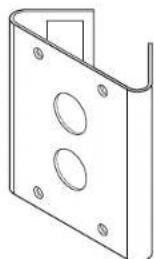
| Dimensions (dome) | Diameter 147 mm, outline 159.5 × 176 mm |
| Weight | 2 kg |
| Care and Cleaning | Clean with a soft cloth; do not use detergents or spray water directly |
| Safety | Use only the supplied adapter; disconnect during storms; do not expose to moisture or shocks |
| Main Features | Motion detection, privacy zones, automatic color/B&W switching, backlight compensation, presets (128 positions), auto modes (pan/round) |
Frequently Asked Questions - SCC643AP SAMSUNG
User questions about SCC643AP SAMSUNG
0 question about this device. Answer the ones you know or ask your own.
Ask a new question about this device
Download the instructions for your Soundbar in PDF format for free! Find your manual SCC643AP - SAMSUNG and take your electronic device back in hand. On this page are published all the documents necessary for the use of your device. SCC643AP by SAMSUNG.
USER MANUAL SCC643AP SAMSUNG
Owner's Instructions
Benutzerhandbuch
The purpose of this information is to ensure proper use of this product to prevent danger or damage to property. Please be sure to observe all precautions.
The precautions are divided into "Warnings" and "Cautions" as distinguished below:
Warning: Ignoring this warning may result in death or serious injury. Caution: Ignoring this caution may result in injury or damage to property.
| Warning instructions alert you to a potential risk of death or serious injury. | Caution instructions alert you to the potential risk of injury or damage to property. |

Warning
- Be sure to use only the supplied adapter. (Using an adapter other than the one supplied may cause fire, electrical shock, or damage to the product.)
- When connecting the power supply and signal wires, check the external connection terminals before connecting them. Connect the alarm signal wires to the alarm terminals, the AC adapter to the AC power input receptacle, and the DC adapter to the DC power input, making sure that the correct polarity is observed. (Connecting the power supply incorrectly may cause fire, electrical shock or damage to the product.)
- Do not connect multiple cameras to a single adapter. (Exceeding the capacity may cause abnormal heat generation or fire.) (A falling camera may cause personal injury.)
- Securely plug the power cord into the power receptacle. (Insecure connection may cause fire.)
-
When installing the camera on a wall or ceiling, fasten it securely and firmly. (A falling camera may cause personal injury.)
-
Do not place conductive objects (e.g., screwdrivers, coins, and metal things) or containers filled with water on top of the camera. (Doing so may cause personal injury due to fire, electrical shock, or falling objects.)
- Do not install the unit in humid, dusty, or sooty locations. (Doing so may cause fire or electrical shock.)
- If any unusual smells or smoke come from the unit, stop using the product. In such case, immediately disconnect the power source and contact the service center. (Continued use in such a condition may cause fire or electrical shock.)
- If this product fails to operate normally, contact the store of purchase or your nearest service center. Never disassemble or modify this product in any way. (SAMSUNG is not liable for problems caused by unauthorized modifications or attempted repair.)
- When cleaning, do not spray water directly onto parts of the product. (Doing so may cause fire or electrical shock.) Wipe the surface with a dry cloth. Never use detergents or chemical cleaners on the product, as this may result in discoloration of surface or cause damage to the finish.

Caution
- Do not drop objects on the product or apply strong shock to it. Keep away from a location subject to excessive vibration or magnetic interference.
- Do not install in a location subject to high temperature (over 122^ ), low temperature (below 14^ ), or high humidity. (Doing so may cause fire or electrical shock.)
- Avoid a location which is exposed to direct sunlight, or near heat sources such as heaters or radiators. (Neglecting to do so may result in a risk of fire.)
- If you want to relocate the already installed product, be sure to turn off the power and then move or reinstall it.
- Install in a well-ventilated location.
- Remove the power plug from the outlet when there is a lightning storm. (Neglecting to do so may cause fire or damage to the product.)
Before Usage
This is a basic instruction manual for the SCC-643(P) user. It contains all the instructions needed to use the SCC-643(P) from a simple introduction of the control locations and functions of the SCC-643(P) to installation methods in the set up menu.
We recommend all users of the SCC-643(P) from the advanced user who has used similar cameras before to the general user to read the instruction manual before using.
The most frequently used feature in the SCC-643(P) would be the SCC-643(P) Setup Menu. The SCC-643(P) Setup Menu is explained in detailed in "Chapter 3 Setup Menu Overview".
The instructional manual is best used when read from beginning to end, but for users wanting to read only the part they need here are the Chapter summaries.
"Chapter 1 SCC-643(P) Overview" includes a brief introduction of the SCC-643(P), part names and functions, and Switch Settings.
"Chapter 2 SCC-643(P) Installation" explains the installation procedures of the SCC-643(P) and provides preparation and installation environment requirements.
"Chapter 3 Setup Menu Overview" presents the structure of the Setup menu for the SCC-643(P) including a detailed explanation of the functions performed in each submenu.
"Appendix SCC-643(P) Product Specifications" contains product specifications of the SCC-643(P) in itemized categories.
Approval of Standards

LISTED 51Y7 E149091. T.E.

LR8100

Note: This equipment has been tested and found to comply with the limits for a Class B digital device, pursuant to part 15 of the FCC Rules. These limits are designed to provide reasonable protection against harmful interface in a residential installation. This equipment generates, uses and can radiate radio frequency energy and, if not installed and used in accordance with the instructions, may cause harmful interference to radio communications. However, there is no guarantee that interference will not occur in a particular installation. If this equipment does cause harmful interference to radio or television reception, which can be determined by turning the equipment off and on, the user is encouraged to try to correct the interference by one or more of the following measures:
Reorient of relocate the receiving antenna.
- Increase the separation between the equipment and receiver.
- Connect the equipment into an outlet on a circuit different from that to which
the receiver is connected.
- Consult the dealer or an experienced radio TV technician for help.
Table of contents
Before Usage 1-1
Chapter 1 SCC-643(P) Overview 1-5
SCC-643(P) Introduction 1-6
SCC-643(P)Locations of Control 1-7
SCC-643(P)FRONT 1-7
SCC-643(P) BACK 1-8
ADAPTER CONNECTION 1-9
INITIAL SETTING 1-10
Setting RS-422A/RS-485 termination 1-11
SWITCH SETTING 1-12
Chapter 2 SCC-643(P) Installation 2-1
Before Installing 2-2
Preparing the Cables 2-3
Cable Connection 2-4
Installing SCC-643(P) 2-5
Installing the Camera 2-8
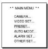
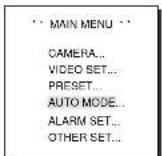
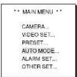
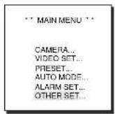
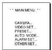
Chapter 3 Setup Menu Overview
Structure of the Setup Menu 3-2
1.CAMERA SET MENU 3-4
CAMERA ID- 3-4
V-SYNC 3-4
-
COLOR/BW 3-5
-
ZOOM SPEED 3-6
-MOTION DET- 3-6
-EXIT 3-7
2.VIDEOSTEMPUN 3-7
- IRIS- 3-7
-ALC 3-8
-
BLC- 3-8
-
MANU- 3-9
-
SHUTTER 3-9
-
AGC -3-10
- S.S. 3-10
- SLOW 3-11
-NORMAL- 3-11
-FAST 3-11
F.F 3-11 - WHITE BAL- 3-12
- SPECIAL 3-14
- AUTO FOCUS 3-15
- D-ZOOM 3-15
-EXIT 3-15
3.PRESET 3-16
4.AUTO MODE- 3-18
-AUTO PAN 3-18 - PATTERN 3-19
5.ALARM SET- 3-20 - OTHER SET 3-22
Appendix Product specifications 3-25
Chapter 1 SCC-643(P) Overview
In this chapter we will briefly introduce the SCC-643(P) and show main functions, locations of control and Switch Setting.
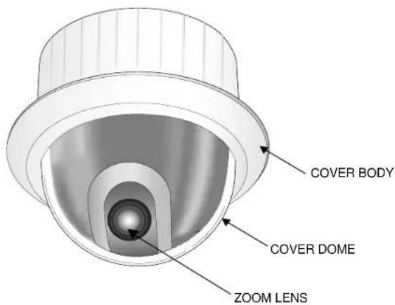
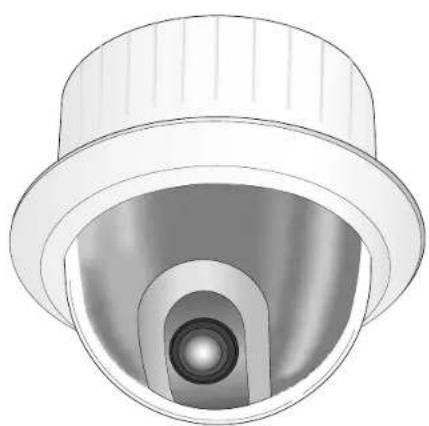
SCC-643(P) Introduction
The SCC-643(P) is the best performing zoom lens integrated surveillance camera. It can be used with CCTV in banks or companies to provide high level of security.
The SCC-643(P) is a high quality surveillance camera using x22 zoom lens and digital zoom IC, it can catch clear images up to 220 times.
The SCC-643(P) is a multifunction camera that is equipped with all of the key functions of the existing surveillance cameras:
- Low-Light Surveillance function that enables image capture even under extremely low light conditions.
- White Balance function that provides accurate color rendition under any light conditions.
- BLC function that enables effective back light compensation even under a spotlight or a very bright incident light.
- Auto-Focus function that automatically tracks and focuses on the moving subject.
- Privacy Zone function that hides certain area of the screen from view to protect individual privacy.
- COLOR/BW function that automatically switches to the BW (Black and White) mode to increase the camera's sensitivity at night or under low light level conditions.
The SCC-643(P) uses an Alarm function for alert situations and moving camera in the direction you want, ZOOM-IN and ZOOM-OUT functions can be remote controlled.
Locations of Control
FRONT
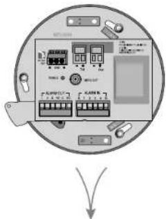
BACK
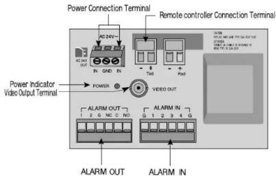
ADAPTER CONNECTION
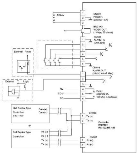
SCC-643(P) Adapter BOARD
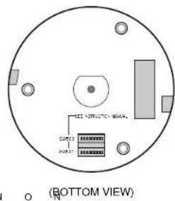
INITIAL SETTING
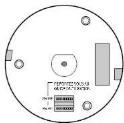
CAMERA ADDRESS SETUP
Dip Switch setting is same as the following example:
EX)CAMERA ADDR:When it's number 1, set as follows.
Setting communication Protocol
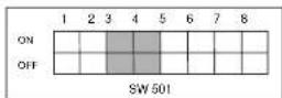
Use number 5~8 PIN of SW501 to set communication Protocol.
| PN Comp | PINS | PING | PIN7 | PINS |
| A OFF | OFF | OFF | OFF | |
| B ON | OFF | OFF | OFF | |
| C OFF | ON | OFF | OFF | |
| D ON | ON | OFF | OFF | |
| E OFF | OFF | ON | OFF | |
| F ON | OFF | ON | OFF | |
| G OFF | ON | ON | OFF | |
| H ON | ON | ON | OFF | |
| I OFF | OFF | OFF | ON | |
| J ON | OFF | OFF | ON | |
| K OFF | ON | OFF | ON | |
| L ON | ON | OFF | ON | |
| M OFF | OFF | ON | ON | |
| N ON | OFF | ON | ON | |
| O OFF | ON | ON | ON | |
| P | O | N | O | N |
A:SAMSUNG(SSC-1000)HALF
B:SAMSUNG(SSC-1000)FULL
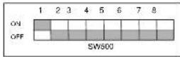
Baud Rate Setting
Use PIN 3 and 4 of SW501.
| BAUD RATE | PIN 3 | PIN 4 |
| 4800 BPS | ON | ON |
| 9600 BPS | OFF | ON |
| 19200 BPS | ON | OFF |
| 38400 BPS | OFF | OFF |
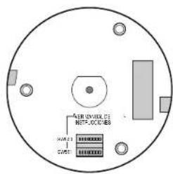
Setting RS-422A/RS-485 termination
As it is shown in the structure map, when Controller and RS-422A/RS-485 is connected it should be terminated according to the Cable feature of impedance on the each end of the transmitting line to transfer the signals in long distance by controlling the reflection of the signals to the lowest.
Termination: using numbers 1 and 2 PIN, turn to ON and it will be terminated.
SWITCH SETTING
Chapter 2 SCC-643(P) Installation
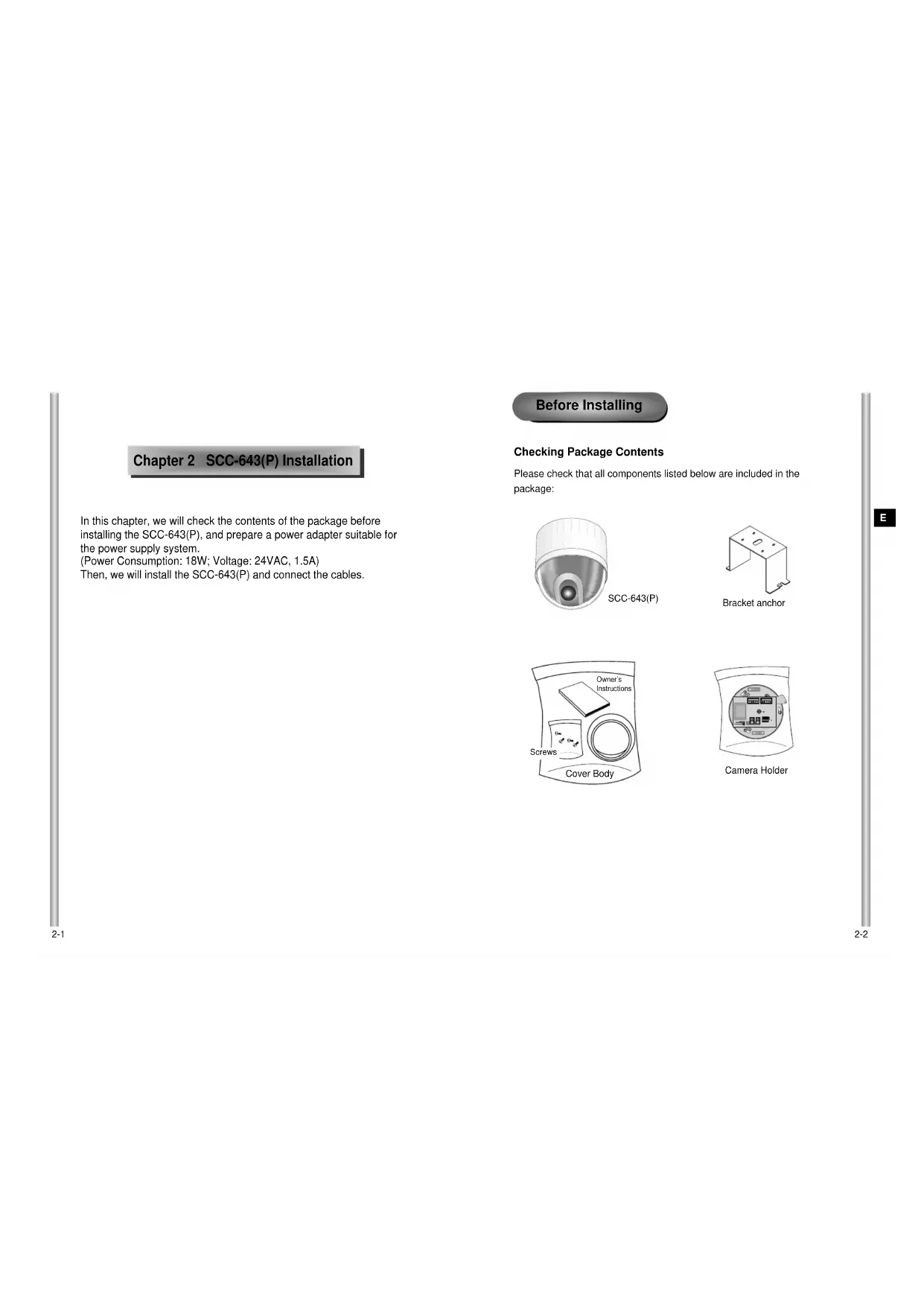
In this chapter, we will check the contents of the package before installing the SCC-643(P), and prepare a power adapter suitable for the power supply system.
(Power Consumption: 18W; Voltage: 24VAC, 1.5A)
Then, we will install the SCC-643(P) and connect the cables.
Before Installing
Checking Package Contents
Please check that all components listed below are included in the package:

Preparing the Cables
To install and use the SCC-643(P), the following cables should be prepared.
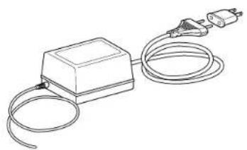
Power Adapter Cable
The cable that plugs into the SCC-643(P) power input receptacle has the rated voltage of 24VAC, 1.5A.
Check the rated voltage before using the cable.
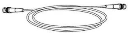
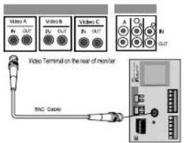
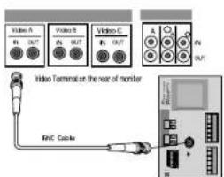
Video Cable
The SCC-643(P)'s cable is a BNC Cable for connecting the video-output terminal to the video-input terminal of the monitor.
Cable Connection
- First, connect one end of the BNC video cable connector to the Video Output Terminal (VIDEO OUT)
- Then, connect the other end of the connector to the Video Input Terminal of the monitor.
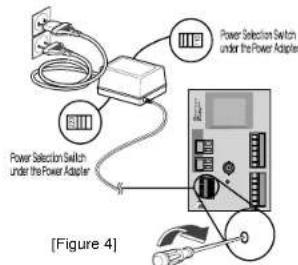
- Now connect the Power Adapter Cable. Use a driver to screw one part of the two lines of Power Adapter to Power Input Terminal of the SCC-643(P).
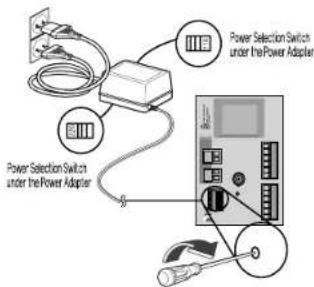
-
Adjust the switch below the Power Adapter to the proper voltage. Then, connect the Power Adapter's plug to the Power Connector.
-
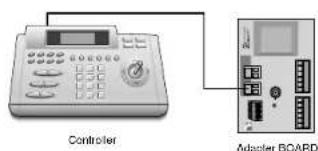
Connect the Remote Control Terminal of the SCC-643(P) and the external Controller.
Installing SCC-643(P)
Installation Precautions
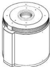
1) Make sure that the installation site can sufficiently support a minimum of four times the net weight of the SCC-643(P) Combi Dome Camera and other accessories.
2) Install in an area where the space above the ceiling board is over 18 cm (7 in.) high.
3) Use the supplied screws to fasten the camera to the bracket assembly.
4) Keep persons away from the installation area, as there is a risk of falling objects.
Also, move valuables to a safe location before installation.
Separately Sold Products for Installation
Depending on the installation site, it may be convenient to use one of the following products.
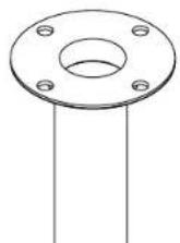
1) CEILING MOUNT BRACKET (SBR-100DCM)
This bracket is used for installing the SMARTDOME CAMERA in the plenum above the drop ceiling.
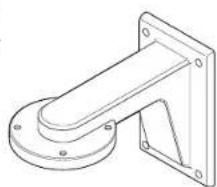
2) WALL MOUNT ADAPTOR (SADT-100WM)
This adaptor is used for installing the indoor housing or the outdoor housing for the Combi Dome Camera on a wall.
3) INDOOR HOUSING (SHG-120)
This housing is used for installing the Combi Dome Camera to an indoor wall or a ceiling.
4) OUTDOOR HOUSING (SHG-220)
This housing is used for installing the Combi Dome Camera to an outdoor wall or a ceiling.
5) CEILING MOUNT ADAPTOR (SADT-100CM)
This adaptor is used for installing the indoor housing or the outdoor housing for the Combi Dome Camera to a concrete ceiling.
6) POLE MOUNT ADAPTOR (SADT-100PM)
This adaptor is used for installing the WALL MOUNT ADPATOR
(SBR-100WM) to a pole that is over 7 cm (2.76 in.) in diameter.
Installing the Camera
- [Figure 1] Install the structure on the ceiling.
(Refer to Installation reference for the Length of the structure)
- Built in by the builder of the structure
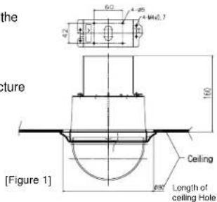
-
Make a hole in the ceiling where the camera will be installed. (The hole should be about 180)
-
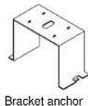
[Figure 2] Assemble the BRKT-ANCHOR on the ceiling and screw the 4 bolts in.
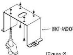
[Figure 2]
- [Figure 3,4] Connect the various cables to the CAMERA ADAPTER. (See page 2-4)
[Figure 3]
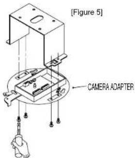
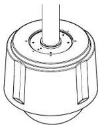
5. [Figure 5] Match the BRKT-ANCHOR and CAMERA ADAPTER and use 4screws (PH M4 x 8) to assemble them.
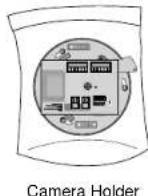
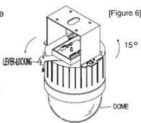
- [Figure 6] Match the 3 holes on the back of the CAMERA and the CONNECTOR and turn it left about 15 degrees. (Check the sound of LOCKING and that the LEVER-LOCKING is in place)
Use the screws (BH M3 x L8) to connect the CAMERA and the ADAPTER so they don't move.
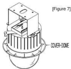
7.[Figure 7] Assemble the COVER-DOME onto the DOME.
Chapter 3 Setup Menu Overview
In this chapter, we will look over the Setup Menu of the SCC-643(P), First we'll look over the overall structure of the Setup Menu, and then we'll look at the functions of each menu.
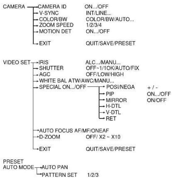
Structure of the Setup Menu
The diagram shown above illustrates the overall structure of the Setup Menu. In this section, a description of the Setup menu features will enable users of the SCC-643(P) to tailor it to their personal needs.
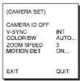
1.CAMERA SET MENU
CAMERA ID
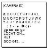
The CAMERA ID menu assigns an ID to the SCC-643(P) to be displayed on the connected monitor. On the CAMERA SET menu screen, select CAMERA ID to ON and press [Enter]. You will see the sub screen for deciding on the ID of the SCC-643(P). The Camera ID can have up to 12 alphanumeric characters, along with several special characters.
The assigned camera ID may be positioned to any desired location on the screen by using the LOCATION submenu.
* ..Means there are Sub Menus.

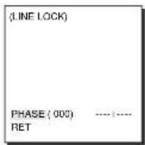
V-SYNC
In the V-SYNC menu, vertical synchronization can be selected. The vertical synchronization signal supported by the SCC-643(P) is the INT mode made by clock inside the SCC-643(P) and LINE mode adjusting vertical synchronization to the exterior power frequency.
Select LINE and press [Enter]. You will see the LINE LOCK submenu where you can adjust the phase of the LINE LOCK. You can use the PHASE menu of the LINE LOCK submenu to assign as much PHASE as you want.

COLOR/BW
In the COLOR/BW menu, you can switch ON or OFF the IR (infrared) Filter.
In low light conditions, IR Filter is turned OFF to the BW Mode and the sensitivity to low light increases to that of a black and white camera. In bright light conditions, the IR Filter is turned ON to the COLOR Mode, and the screen changes to normal as the sensitivity decreases.
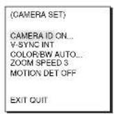
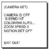
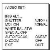
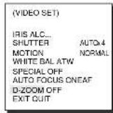
(CAMERA SET)
CAMERA ID OFF
V-SYNC IN
COLOR/BW AUTO...
ZOOM SPEED 3
MOTION DET OFF
EXITOUT
COLOR : The IR Filter is ON and the screen is normal. BW : The IR Filter is OFF and the screen is black and v
(Sensitivity to low light is increased to a level comparable to a black and white camera.)
AUTO: Select to automatically switch between the COLOR mode and BW mode depending on the amount of light. In low light conditions, the IR Filter is turned OFF and the sensitivity to low light is increased by switching to the BW mode, but in bright light conditions, the IR Filter is turned ON and the sensitivity is decreased by switching to the COLOR mode. If you select AUTO and press the ENTER button, a screen from which you can set the BURST ON / OFF, BW LEVEL and DWELL TIME will appear.
- BURST ON: The color burst signal is output together with black and white composite video signal.
- BURST OFF: The color burst signal is not output.
- LEVEL: You can set the brightness level that changes from COLOR mode to BW mode in 3 steps: LOW, MEDIUM, and HIGH.
- DWELL TIME: Set the HOLDING time for switching between COLOR and BW mode depending the changes in the amount of light. You can set the HOLDING time to 10sec(S), 30sec, 60sec, or 300sec(L).
In AUTO mode, AGC will operates in high speed mode, and you cannot change it manually, as it is indicated by "---".

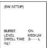
Caution: If you use an infrared light source while in AUTO mode, AUTO switching malfunction and camera AF malfunction may occur.
ZOOM SPEED
In the ZOOM SPEED menu you can select the speed of the ZOOM Key (Tele/Wide).
Use the [Left] or [Right] keys in the ZOOM SPEED menu to select the speed.
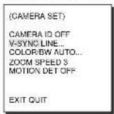
(CAMERA SETI)
CAMERA ID OFF
V.SYNC INT
COLOR/BW AUTO
ZOOM SPEED 3
MOTION DET OFF
EXIT QUIT
1: Magnification x 22 takes about 18 seconds. Slowest speed
2 : Magnification x 22 takes about 10 seconds . Low speed3 : Magnification x 22 takes about 6 seconds . High speed
4: Magnification x 22 takes about 4 seconds. Fastest speed
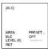
MOTION DET
In MOTION DET, you can set the Motion Detection function, Motion Detection Sensitivity, and the Area of Motion Detection. If the Motion Detection function is set, the movement of an intruder can be detected. When motion is detected, it sets off the Alarm signal of the Controller.

Press [Enter]

AREA PRESET. SENSITIVITY MEDIUM
If you select ON and press the [ENTER] key, the "MOTION DET" submenu screen will come up.
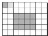
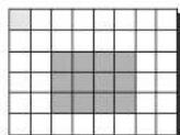
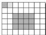
The "AREA" menu, from which you can specify screen areas where the Motion Detection function will be applied, can be set to either PRESET or USER. If you set the "AREA" menu to PRESET, the Motion Detection function will be applied to the areas preset as factory defaults.
If you set the AREA menu to USER and press the [ENTER] key, you can choose from 48 areas where you want to apply the Motion Detection function. Use the [5] key and [left, right, up, down] keys to move and select the motion detection area.
Press the [5] key to assign an area or to cancel the area.
If you press [ENTER] once more, you will exit the "AREA" setting menu. Use the "SENSITIVITY" menu to set the sensitivity of the MOTION Detection. The Higher it is set, the more sensitive the Motion Detection moves.
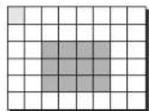

Use the [Left, Right, Up, Down] Keys Press the [5] key to assign an area or to cancel the area.
Motion Detection function does not operate while handling slow SHUTTER, PRESET, SCAN, AUTO MODE(AUTO PAN, PATTERN) or MANUAL KEY (JOYSTICK, ZOOM, FOCUS, IRIS).
EXIT
The EXIT menu is used to quit the CAMERA SET menu of the SCC-643(P) and return to the MAIN MENU.
- QUIT: Ignores the changed information and restores the saved information.
SAVE: Saves the information of the setting condition of the menu. - PRESET: Ignores the changed information and restores the initial factory defaults of the menu.
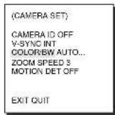
(CAMERA SET)
CAMERA IQ OFF V-SYNC INT COLOR/EW/SYMBOL ZOOM SPEED 3 MOLECULE DETOH
EXIT QUT
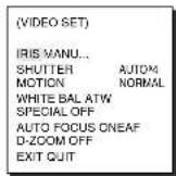
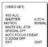
2.VIDEO SET MENU
IRIS
The video output level of the monitor can be controlled by the IRIS lens depending on the level of the incoming light. The video output level can be set in the ALC menu. The opening and shutting of the Iris lens can be set manually in the MANU menu.
ALC
Choose the ALC of the IRIS item and press [ENTER] and set he submenu to the Video Output level and BLC will be shown. The Video Output Level can be set in the level item using the [Left, Right] keys.
BLC (Submenu of the ALC menu)
With conventional cameras, strong background lighting interferes with the clarity of objects, making them appear dark. In the SCC-643(P), setting the BLC (Back Light Compensation), submenu of ALC/MANU menu, will solve the problem of backlight and give you a clear screen.
Set the BLC menu to ON and the Back Light Compensation function will be applied to the screen areas of AREA menu. The screen area where Back Light Compensation should be applied can be set with the PRESET or USER item.If the AREA menu is set to PRESET, the backlight compensation function is applied to the factory defaults of the SCC-643(P).
If the AREA menu is set to USER and [ENTER] is pressed, the user can select the applied area of the backlight compensation function.

Press [Enter]
Use the [left, right, up, down] keys to move to the area you want.
Press the [5] key to assign an area or to cancel the area.
Press the [ENTER] key again to exit the "AREA" setup menu.

Use the
[Left, Right, Up, Down] Keys
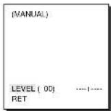
MANU
If the IRIS item is set to MANU, the sub screen to open and shut the Iris manually will be shown. Using the [Left, Right] keys in the LEVEL item you can set Iris manual setting.

Press [Enter]
SHUTTER
In the SHUTTER menu, the high-speed Electric shutter and AUTO low speed shutter of the SCC-643(P) and the FIX low speed shutter can be set. The High speed Electric Shutter supports 7 different speeds from 1/100 to 1/10K of a second. The AUTO low speed shutter and FIX low speed shutter supports 12 different speeds from 2x to 128x magnifications.
The Low speed shutter is the function that sets the shutter speed to low in order to clearly see the object filmed in low light. To automatically slow down the speed of the shutter by sensing the brightness of the light, set to AUTO low speed shutter, and if the user wants to manually set the speed of low speed shutter, set it to FIX. The number after the AUTO and FIX are the number of the fields stored. The larger the number of the fields, the slower the shutter speed gets, so in a still screen the screen is much clearer. If the object were in motion it would be blurry.
If your press the left/right keys continuously, the speed will appear in the following order.
Order
OFF 1 / 100(1 / 120) 1 / 250 1 / 500 1 / 1000 1 / 2000 1 / 4000 1 / 10K OFF AUTOX2 AUTOX4 AUTOX6 AUTOX8 AUTOX12 AUTOX16 AUTOX24 AUTOX32 AUTOX48 AUTOX64 AUTOX96 AUTOX128 OFF FIX X2 FIX X4 FIX X6 FIX X8 FIX X12 FIX X16 FIX X24 FIX X32 FIX X48 FIX X64 FIX X96 FIX X128
AGC
In the AGC menu, you can specify whether to automatically control the GAIN when the obtained video is below a certain level of brightness. To automatically control the GAIN, set the AGC menu to LOW/HIGH. Otherwise, set it to OFF.
If the you set the AGC to LOW, the maximum GAIN of the AGC will be set to low, and if set to HIGH, the maximum GAIN will be set to high. Under low light conditions, SHUTTER Mode change from AGC to MOTION (AUTO Mode). In the MOTION, use the [left, right] keys to select "S.S/SLOW/NORMAL/FAST/F.F".
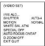
(VIDEO SET)
IRIS ALC
SHUTTERT OFF
AGC LOW
WHITE BAL ATW
SPECIAL OFF
AUTO FOCUS ONEAF
D-ZOOM OFF
EXIT OUT
S.S
This maximally enhances the resolution of a still image by selecting the lowest value for AGC GAIN and the slowest speed for SHUTTER SPEED. (This is used mainly to monitor inanimate objects in dark places.)
SLOW
This enhances the resolution of a still image by selecting a low value for AGC GAIN and a slow speed for SHUTTER SPEED.
(This is used mainly to monitor inanimate objects in dark places.)
NORMAL
This shows the normal picture by selecting a medium value for AGC GAIN and the normal speed for SHUTTER SPEED.
(This is used mainly to monitor moving objects in dark places.)
FAST
This focuses on the moving object by selecting a high value for AGC GAIN and a high speed for SHUTTER SPEED.
(This is used mainly to monitor objects moving conspicuously in dark places.)
F.F
This focuses on the fastest moving object by selecting the highest value for AGC GAIN and the fastest speed for SHUTTER SPEED.
(This is used mainly to monitor fast moving objects in dark places.)
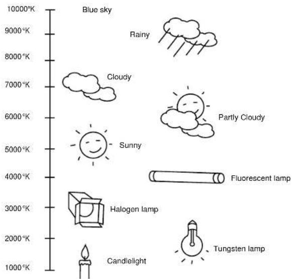
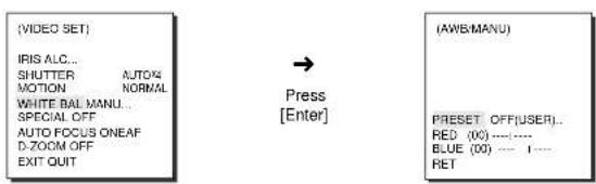
WHITE BAL
Lights are generally denoted as color temperatures and expressed in Kelvin (^) units.
The general light color temperatures are shown below.
WHITE BAL
The WHITE BAL menu insures that white is calibrated normally under any color temperature condition.
- When the WHITE BAL menu is set to the ATW mode, the white balance is automatically specified according to the color temperature.
- In the case of setting the WHITE BAL menu to AWC mode, pressing [ENTER] while having a white paper in front of the Camera will automatically set the white balance in accordance with the color temperature only one time.
-
If WHITE BAL menu is set to MANUAL mode, the user can set the white Balance considering the current illumination.
-
3200^ : Set color temperature to 3200^
- 5600°K : Set color temperature to 5600°K
- User : Set the appropriate value in the RED and BULE graph.
MANU: Select MANU item and press [ENTER], the sub screen where you can select Manual White Balance will be shown.
Use the left/right keys to select 3200^ , 5600^ or USER mode in the PRESET menu.
SPECIAL
In the SPECIAL menu, POSI/NEGA, PIP, Mirror, and vertical and horizontal detail level can be adjusted.
- POSI/NEGA: Video output signal is outputted normal/reverse.
-
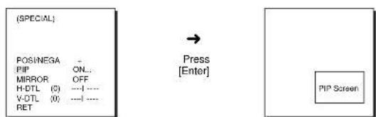
PIP(Picture in Picture): When Digital Zoom is activated, the 1/16 minimized screen will be shown.
-
MIRROR: Reverse the video output signal horizontally.
H-DTL: Adjust Horizontal Detail Level.
V-DTL: Adjust Vertical Detail Level.
Select ON and press [ENTER], the "SPECIAL" submenu to choose the special functions will be shown.
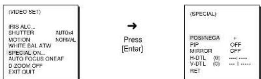
To choose functions use the left/right keys to select an item. In the PIP menu, select ON and press [ENTER]. Use the [left, right, up, down] keys to set the location of the PIP.
The PIP function does not work in the slow-speed Shutter Mode and Privacy Zone Display Mode, and the Mirror function does not work in the PIP window.
* The Mirror function does not work if Privacy Zone is set.
AUTO FOCUS
In the AUTO FOCUS MENU, the Focus method can be set to AF, MF, or ONEAF.
- AF: With AUTO FOCUS MODE, you can monitor the screen continuously and it will focus automatically. While moving the zoom keys, it will automatically focus so FOCUS key input is not necessary.
-MF: In MANUAL FOCUS MODE the user adjusts the Focus manually. - ONEAF: The ONEAF Mode performs Auto-focusing only when the SCC-643(P) stops after moving and when the SCC-643(P) is not moving it is same as MF mode.
(The ONEAF Mode does not work when zooming out.
* When in the MF/ONEAF Mode, press the NEAR and FAR keys on the Controller (SSC-1000) at the same time to perform AUTO FOCUS.
Use the left/right keys to select AF, MF or ONEAF in the AUTO FOCUS menu.
D-ZOOM
In the D-ZOOM menu, you can choose the Digital Zoom magnification. You can select a magnification from OFF to 10 times.
When Digital Zoom is selected at 10 times, the camera can show upto 220 times because the Optical Zoom is 22 times.
Use the [left, right] keys to select the magnification in the D-ZOOM menu.
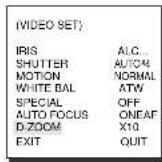
EXIT
It's the same as the EXIT function of the CAMERA SET menu.
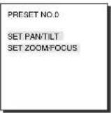
3. PRESET
This is the menu that user sets the PAN/TILT location, Zoom/Focus, and screen condition, so the camera can monitor the presetting area on demand. A total of 128 presets are available.
Among the 128 PRESETS HOME POSITION, PRESET 1: ALARM1, PRESET 2: ALARM2, PRESET 3: ALARM3, PRESET 4:
ALARM4, PRESET 5: set as special preset corresponding MOTION.


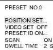
* "... "Means there are Sub Menus.
POSITION SET...
From "POSITION SET..." press [ENTER] to get into the PAN/TILT, FOCUS/ZOOM SET screen to set the PAN/TILT location and FOCUS/ZOOM condition then press [ENTER] to return to a higher menu.
VIDEO SET
This is the screen setting function for each PRESET. Refer to the explanation under "VIDEO SET menu".
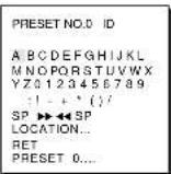
PRESET ID
This is the ID set up function for each PRESET. It can be set up to 12 characters using the left, right, up, and down keys.
The ID location can be set in the submenu of "LOCATION..."
SCAN
This function sets up for movement or no movement in "SCAN" motion. When it's PRESET to "ON" it includes SCAN motion and to "OFF" no movement.
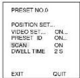
DWELL TIME
This is a function setting for the DWELL TIME of the PRESET location in "SCAN" motion. It can set DWELL TIME From 1 ~ 60 Sec.
EXIT
"QUIT": Does not save the selected information and returns to a higher menu.
"SAVE": Do saves the selected information and returns to a higher menu.
"DEL": deletes the selected information and restores the DEFAULT. Then returns to a higher menu.
4.AUTO MODE
AUTO PAN and PATTERN functions are in AUTO MODE.
AUTO PAN
After selecting the locations of two points (PAN/TILT) of START and END, it loops continuously in the set up SPEED.

Press [F#]
[EN10]
(AUTO MODE)
AUTO PAN
PATTERN SET 1...


Press
[Enter]
AUTOPAH
START SET
END SET...
DIRECTION RIGHT
ENOLESS ON
SPEED STEPS
DVEEELI
EXIT QUIT
START SET
From "START SET...", get into the START SET setup screen by pressing [ENTER]. After selecting the locations of PAN/TILT location, press [ENTER] again to return to higher menu.
END SET
From "END SET...", get into the END SET setup screen by pressing [ENTER]. Adjust PAN/TILT location and press [ENTER] to return to a higher menu.


DIRECTION
This sets up the movement direction of the START to END location (PAN location standard)
"RIGHT"
"LEFT":
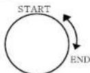
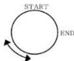
ENDLESS
This is a 360-degree rotation function that stops for the DWELL TIME only in the START and END positions without running between the START and END positions. It can be set to "ON" or "OFF".
SPEED
This is a setting function for movement speed setup. It can be set from STEP1 to STEP64.
DWELL TIME
This is a function for setting up the time to stay in the START to END position.
PATTERN
This is a replay function so that the MANUAL functions such as PAN, TILT, ZOOM, and FOCUS are played for 30 seconds.

Press [Enter]

Press [Enter]

AUTO PAN
PATTERN SET 1
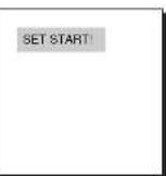
PATTERN can be set upto 3. Choose 1, 2, or 3 with the left or right key in the "PATTERN SET" and press [ENTER] to get into the PATTERN set up screen. From the moment "PATTERN 1 SET" is gone for 30 seconds, it memorizes the MANUAL movements and after 30 seconds it will return to a higher menu. If you want to finish set up before the 30-second ends, press [ENTER].
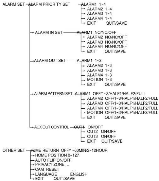
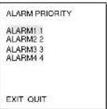
5. ALARM SET
It consists of 4 ALARM INPUTs and 3 ALARM OUTs. It can sense an ALARM input from exterior SENSORS and it performs with PRESET or PATTERN function and outputs the ALARM OUT signals. It recognizes the ALARM signal input as an ALARM signal when it continues more than 150ms for a time and each ALARM movement time is decided depending on its correspondence to the DWELL TIME of the PRESET and PATTERN connected.


(ALARM SET)
ALARM PRIORITY SET. ALARM IN SET. ALARM OUT SET. ALARM CONTROL SET. AUX OUT CONTROL.
NET
ALARM PRIORITY SET
This sets the priority of the 4 ALARM inputs so ALARM can work corresponding to the priority. The priority of the DEFAULT is ALARM1: 1, ALARM2: 2, ALARM3: 3, ALARM4: 4, MOTION: 5. If the ALARM is working at the same time and the priority is the same, it will operate according to the DEFAULT priority. While the ALARM is working, it cannot detect MOTION.
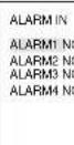
ALARM IN SET
This sets the input TYPE to "NO" (Normal Open), "NC" (Normal Close), or "OFF" depending on the features of the SENSOR connected.
ALARM OUT
Each ALARM input corresponds to one of the 3 ALARM OUT.
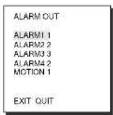
ALARM PATTERN
This sets the operation of PATTERN movements when inputting ALARM.
When the ALARM is working, it will stay in the PRESET location corresponding the ALARM for the DWELL TIME and the ALARM connected to the PATTERN will continuously operate the PATTERN movements.
When the ALARM is inputted the correspondence will be as follows: ALARM1 input to PRESET 1, ALARM2 input to PRESET 2, ALARM3 input to PRESET 3, ALARM4 input to PRESET 4, and MOTION input to PRESET 5.
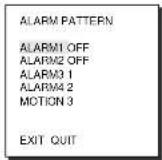
The OFF in the Setup Menu does not operate the PATTERN, and it means 1 PATTERN1, 2 PATTERN2, 3 PATTERN3, HALF1 continuous motion of PATTERN 1 + PATTERN 2, HALF 2 continuous motion of PATTERN 2 + PATTERN 3 and FULL continuous motion of PATTERN 1+PATTERN2+PATTERN3.
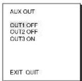
AUX OUT CONTROL
This sets the ALARM OUT motion to continue or act only when the ALARM is working. If it is set to OFF the ALARM OUT motion will operate only when the ALARM is working. (Active "Low"), and if it's set to ON, the ALARM OUT will always operate regardless of the ALARM.
6. OTHER SET
HOME RETURN
When there is no KEY input or other movement for a certain time, the camera moves to the HOME location automatically. The HOME location can be assigned from the HOME POSITION menu.

Press
[Enter]

HOME RETURN 12HOUR
HOMEPOsTION0
AUTOLFLIP ON
PROVACZONE CAMRESET
LANGUAGE ENGLISH
EXIT OUT
SET UP TIME FOR HOME RETURN:
OFF: HOME RETURN function cancellation
$$ O F F \rightarrow 1 M I N \rightarrow 2 M I N \rightarrow 3 M I N \sim 6 0 M I N \rightarrow - 1 2 H O U R $$
HOME POSITION
You can select the HOME POSITION from the preset positions numbered between 0 and 127.
AUTOFLIP
When operating the Tilt to the 90^ limit using the Joystick, the camera PAN automatically revolves 180^ showing the opposite area of the Tilt area. It gives the effect of extending the Tilt operating area 180^ .

[Enter]
KEY
(OTHERS)
HOME RETURN 12HOUR
HOME POSITION 0
AUTOFLIP ON PRIVACY ZONE
CAMRESET
LANGUAGE ENGLISH
EXIT
OUT
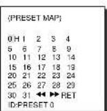
PRIVACY ZONE
Pan/Tilt position and the size of Masking area can be set for up to 8 privacy zones. When shooting the areas where privacy zones are set, the relevant areas will be concealed from view to protect privacy.
Privacy Zones can be set as follows:

Select PRIVACY ZONE and press the [Enter] key. The PRIVACY ZONE Map appears and an asterisk *** is placed next to the numbers set.
Use the [up, down, left, right] keys to select a number you want to set, and then press the [Enter] key.
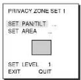

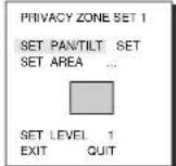

When the above screen appears, press the [Enter] key while the SET PAN/TILT is selected to set the Pan/Tilt position. With OSD showing "SET", use the Joystick move the Masking area to the center.
After setting the position, press the [Enter] key again to exit the PAN/TILT position setup.
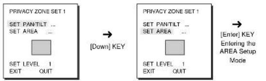
To set the area, select "SET AREA" and then press the [Enter] key. With OSD showing "SET", use the [up, down, left, right] key to set the AREA size.
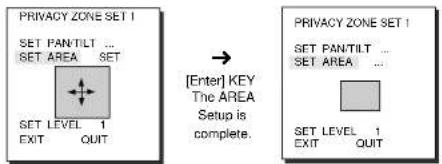
Select "SET LEVEL" and set the Level of Mask Area.
This Level can be set anywhere from 1 (black) to 8 (white), and the set level will be applied to all eight areas.
"SAVE" and exit after setting the Level to complete the settings for the Privacy Zone.
- Make the area large enough so that the relevant area can be hidden underneath it.
CAM RESET
CAM RESET clears all the settings made so far and restores the factory default settings.
"CAMERA RESET?" message appears when you select CAM RESET. Select "CANCEL" to return to the menu setup display or select OK to restore the factory default settings.
- Be careful when performing a CAM RESET operation, as it deletes all setup values.
Product specifications
| NO | Items | Contents | |
| 1 | Product Type | - Zoom lens single body COMBI DOME CAMERA | |
| 2 | Power Input | - AC 24 + 10% (60Hz + 0.3Hz) | |
| 3 | Power Consumption | -18W | |
| 4 | Broadcasting Type | - NTSC STANDARD COLOR SYSTEM | |
| 5 | Image Device | - 1/4 inch IT CCD | |
| 6 | Effective Pixels | - 768(H) x 494(V) | |
| 7 | Scanning Mode | - 525 Lines, 2:1 Interface | |
| 8 | Scanning line Frequency | - Horizontal : 15, 734 Hz(INT) / 15, 750 Hz(L/L)Vertical : 59.94 Hz(INT) / 60 Hz(L/L) | |
| 9 | Synchronization Mode | - INT/LINE LOCK | |
| 10 | Resolution | - 480 TV LINES | |
| 11 | S/N Ratio | - 52dB (AGC OFF) | |
| 12 | Min. Object Illumination | - 0.3 Lux (SENS UP X4)(0.01 Lux)- B/W: 0.4 Lux(0.003 Lux) | |
| 13 | Color Temperature | - ATWAWC/MANUAL MODE(3200*K, 5600*K, RGB GAIN Count) | |
| 14 | Signal Output | - COMPOSITE VIDEO OUT : 1.0 Vp-p 75 ohms/BNC | |
| 15 | Lens | - one body; 22xZoom lens-Focal length : 3.6 to 79.2 mm-Aperture : F1.6(Wide), F3.8(Tele)- Auto Focus | |
| 16 | PAN Function | - PAN range : 360° Endless-Preset Pan Speed : 240°/sec, maximum-Manual Pan Speed : 0.8° - 90°/sec (64Step) | |
| 17 | TILT Function | - TILT range : 0° - 90°- Preset Till Speed : 150°/sec, maximum-Manual Till Speed : 0.8° - 45°/sec (64Step) | |
| 18 | REMOTE CONTROL | - Tele/Wide(ZOOM), Near/Far(FOCUS),Iris Open/Close, Pan/Tilt | |
| 19 | ALARM | - Alarm Inputs : 4 IN(5mA Sink)- Alarm Outputs : 3 OUT (Open collector : 2DC24V 40mA Max, Relay : 1, NO, NC, COM2A 30VDC, 0.5A 125VAC Max) | |
| 20 | Operation Temperature | - 14°F ~ 122°F | |
| 21 | Operation Humidity | --90% | |
| 22 | SIZE | - DOME : 147 (ø),Outline : 159.5(a) x 176(H)(Adapter:23.5(H)mm) | |
| 23 | Weight | - 2Kg |
Product specifications
SCC-643P
| NO | Items | Contents |
| 1 | Product Type | - Zoom lens single body COMBI DOME CAMERA |
| 2 | Power Input | - AC 24 ± 10% (50Hz ± 0.3Hz) |
| 3 | Power Consumption | - 18W |
| 4 | Broadcasting Type | - PAL STANDARD COLOR SYSTEM |
| 5 | Image Device | - 1/4 inch IT CCD |
| 6 | Effective Pixels | - 752(H) x 582(V) |
| 7 | Scanning Mode | - 625 Lines, 2:1 Interface |
| 8 | Scanning line Frequency | - Horizontal : 15, 625 Hz(INT) / 15, 625 Hz(L/L)Vertical : 50 Hz(INT) / 50 Hz(L/L) |
| 9 | Synchronization Mode | - INT/LINE LOCK |
| 10 | Resolution | - 480 TV LINES |
| 11 | S/N Ratio | - 52dB (AGC OFF) |
| 12 | Min. Object Illumination | - 0.3 Lux (SENS UP X4)(0.01 Lux)- B/W: 0.4 Lux(0.003 Lux) |
| 13 | Color Temperature | - ATW/AWC/MANUAL MODE(3200°K, 5600°K, R/B GAIN Court) |
| 14 | Signal Output | - COMPOSITE VIDEO OUT : 1.0 Vp-p 75 ohms/BNC |
| 15 | Lens | - one body; 22x Zoom lens- Focal length : 3.6 to 79.2 mm- Aperture : F1.6(Wide), F3.8(Tele)- Auto Focus |
| 16 | PAN Function | - PAN range : 360° Endless- Preset Pan Speed : 240°/sec, maximum- Manual Pan Speed : 0.8° ~ 90°/sec (64Step) |
| 17 | TILT Function | - TILT range : 0° ~ 90°- Preset Tilt Speed : 150°/sec, maximum- Manual Tilt Speed : 0.8° ~ 45°/sec (64Step) |
| 18 | REMOTE CONTROL | - Tele/Wide(ZOOM), Near/Far(FOCUS),Iris Open/Close, Pan/Till |
| 19 | ALARM | - Alarm Inputs : 4 IN(5mA Sink)- Alarm Outputs : 3 OUT (Open collector : 2DC24V 40mA Max, Relay : 1, NO, NC, COM2A 30VDC, 0.5A 125VAC Max) |
| 20 | Operation Temperature | - 14°F ~ 122°F |
| 21 | Operation Humidity | - 90% |
| 22 | SIZE | - DOME : 147(a),Outline : 159.5(a) x 176(H)(Adapter:23.5(H)mm) |
| 23 | Weight | - 2Kg |
Cautions
- The copyright of the manual belongs to Samsung Electronics Co., Ltd.
- Without the permission of Samsung Electronics it cannot be reproduced electronically, mechanically, audibly, or by any other method.
- This manual will be modified according to product enhancements.

Combi Dome Camera
SCC-643(P)
Benutzerhandbuch

Sicherheitshinweise
SCC-643(P) Avant 1-7
SCC-643(P) Arriere 1-8
A:SAMSUNGSSC-1000HALF
B:SAMSUNG(SSC-1000)FULL
(VUE DE DESSOUS)
ARLME11
ARLME22
ARLME33
ARLME44
SORTE QUITTER
ENT ALABME
ALARMET NO 1 ALARMET NE 2 ALARMET NO 3 ALARMET NE 4
SORTEOUTTER
PR SORT ALARME
Chaque entree d'ALARME correspond a un de 3d'SORT ALARME.
PR RONDE ALARME
SCC-643(P)Frontal 1-7
SCC-643(P) Localizacion de controles - Posterior 1-8
A:SAMSUNG(SSC-1000)HALF
B:SAMSUNG(SSC-1000)FULL
(VISTA INFERIOR)
PROG PANTILT PROG ZUMBIDO/FOCO