WKS 17125 RE - Grinder BTI - Free user manual and instructions
Find the device manual for free WKS 17125 RE BTI in PDF.

| Features | Details |
|---|---|
| Product type | Shredder |
| Power | 1700 W |
| Tank capacity | 50 L |
| Dimensions | 120 x 60 x 80 cm |
| Weight | 45 kg |
| Compatible materials | Garden waste, branches, leaves |
| Safety system | Overload protection |
| Usage | Ideal for shredding green waste and small branches |
| Maintenance | Regularly check blades and clean the tank |
| Warranty | 2 years |
Frequently Asked Questions - WKS 17125 RE BTI
User questions about WKS 17125 RE BTI
0 question about this device. Answer the ones you know or ask your own.
Ask a new question about this device
Download the instructions for your Grinder in PDF format for free! Find your manual WKS 17125 RE - BTI and take your electronic device back in hand. On this page are published all the documents necessary for the use of your device. WKS 17125 RE by BTI.
USER MANUAL WKS 17125 RE BTI
Original Instructions
natural_image
3D rendering of two types of industrial grinding machines (no text or symbols visible)ppa. Stephan Uder Head of Procurement Department
ppa. Christian Hasenest Head of Business Unit Construction

ppa. Cal V
natural_image
Illustration of a mechanical tool interacting with stacked blocks and a diamond-shaped object (no text or symbols)natural_image
Illustration of a mechanical tool interacting with an I-beam (no text or symbols present)natural_image
Illustration of a hand using a tool to mark a cross-shaped object with a star symbol (no text or labels)ppa. Stephan Uder Head of Procurement Department
ppa. Christian Hasenest Head of Business Unit Construction

text_image
ppa.196 ppa.Cal Vdnatural_image
Illustration of geometric construction tools including a ruler, square planter, and angle measuring tool (no text or symbols)natural_image
Illustration of a mechanical tool interacting with a metallic I-beam (no text or symbols present)natural_image
Illustration of a hand using a tool to mark a cross-shaped symbol (no text or labels)natural_image
Diagram of a hand using a tool to clean or store material over a metal I-beam (no text or symbols present)natural_image
Two bicycle icons with a diagonal line crossing them, no text or symbols presentppa. Stephan Uder Head of Procurement Department
ppa. Christian Hasenest Head of Business Unit Construction

text_image
ppa.106 ppa.Cold UWnatural_image
Two bicycle icons on a diagonal line, one with a person riding and the other with a cyclist (no text or symbols)Girar o cabeçote de en- grenagens
General Power Tool Safety Warnings

WARNING
Read all safety warnings and all instructions. Failure to follow the
warnings and instructions may result in electric shock, fire and/or serious injury.
Save all warnings and instructions for future reference.
The term “power tool” in the warnings refers to your mains-operated (corded) power tool or battery-operated (cordless) power tool.
Work area safety
▶ Keep work area clean and well lit. Cluttered or dark areas invite accidents.
▶ Do not operate power tools in explosive atmospheres, such as in the presence of flammable liquids, gases or dust. Power tools create sparks which may ignite the dust or fumes.
- Keep children and bystanders away while operating a power tool. Distractions can cause you to lose control.
Electrical safety
▶ Power tool plugs must match the outlet. Never modify the plug in any way. Do not use any adapter plugs with earthed (grounded) power tools. Unmodified plugs and matching outlets will reduce risk of electric shock.
- Avoid body contact with earthed or grounded surfaces, such as pipes, radiators, ranges and refrigerators. There is an increased risk of electric shock if your body is earthed or grounded.
▶ Do not expose power tools to rain or wet conditions. Water entering a power tool will increase the risk of electric shock.
▶ Do not abuse the cord. Never use the cord for carrying, pulling or unplugging the power tool. Keep cord away from heat, oil, sharp edges and moving parts. Damaged or entangled cords increase the risk of electric shock.
▶ When operating a power tool outdoors, use an extension cord suitable for outdoor use. Use of a cord suitable for outdoor use reduces the risk of electric shock.
▶ If operating a power tool in a damp location is unavoidable, use a residual current device (RCD) protected supply. Use of an RCD reduces the risk of electric shock.
Personal safety
▶ Stay alert, watch what you are doing and use common sense when operating a power tool. Do not use a power tool while you are tired or under the influence of drugs, alcohol or medication. A moment of inattention while operating power tools may result in serious personal injury.
▶ Use personal protective equipment. Always wear eye protection. Protective equipment such as dust mask, non-skid safety shoes, hard hat, or hearing protection used for appropriate conditions will reduce personal injuries.
▶ Prevent unintentional starting. Ensure the switch is in the off-position before connecting to power source and/or battery pack, picking up or carrying the tool. Carrying power tools with your finger on the switch or energising power tools that have the switch on invites accidents.
▶ Remove any adjusting key or wrench before turning the power tool on. A wrench or a key left attached to a rotating part of the power tool may result in personal injury.
▶ Do not overreach. Keep proper footing and balance at all times. This enables better control of the power tool in unexpected situations.
▶ Dress properly. Do not wear loose clothing or jewellery. Keep your hair, clothing and gloves away from moving parts. Loose clothes, jewellery or long hair can be caught in moving parts.
▶ If devices are provided for the connection of dust extraction and collection facilities, ensure these are connected and properly used. Use of dust collection can reduce dust-related hazards.
Power tool use and care
▶ Do not force the power tool. Use the correct power tool for your application. The correct power tool will do the job better and safer at the rate for which it was designed.
▶ Do not use the power tool if the switch does not turn it on and off. Any power tool that cannot be controlled with the switch is dangerous and must be repaired.
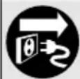
▶ Disconnect the plug from the power source and/or the battery pack from the power tool before making any adjustments, changing accessories, or storing power tools. Such preventive safety measures reduce the risk of starting the power tool accidentally.
- Store idle power tools out of the reach of children and do not allow persons unfamiliar with the power tool or these instructions to operate the power tool. Power tools are dangerous in the hands of untrained users.
- Maintain power tools. Check for misalignment or binding of moving parts, breakage of parts and any other condition that may affect the power tool's operation. If damaged, have the power tool repaired before use. Many accidents are caused by poorly maintained power tools.
▶ Keep cutting tools sharp and clean. Properly maintained cutting tools with sharp cutting edges are less likely to bind and are easier to control.
▶ Use the power tool, accessories and tool bits etc. in accordance with these instructions, taking into account the working conditions and the work to be performed. Use of the power tool for operations different from those intended could result in a hazardous situation.
Service
▶ Have your power tool serviced by a qualified repair person using only identical replacement parts. This will ensure that the safety of the power tool is maintained.
Safety Warnings for Angle Grinder
Safety Warnings common for Grinding, Sanding, Wire Brushing or Abrasive Cutting Off Operations
This power tool is intended to function as a grinder, sander, wire brush or cut-off tool. Read all safety warnings, instructions, illustrations and specifications provided with this power tool. Failure to follow all instructions listed below may result in electric shock, fire and/or serious injury.
▶ Operations such as polishing are not recommended to be performed with this power tool. Operations for which the power tool was not designed may create a hazard and cause personal injury.
▶ Do not use accessories which are not specifically designed and recommended by the tool manufacturer. Just because the accessory can be attached to your power tool, it does not assure safe operation.
The rated speed of the accessory must be at least equal to the maximum speed marked on the power tool. Accessories running faster than their rated speed can break and fly apart.
The outside diameter and the thickness of your accessory must be within the capacity rating of your power tool. Incorrectly sized accessories cannot be adequately guarded or controlled.
Threaded mounting of accessories must match the grinder spindle thread. For accessories mounted by flanges, the arbour hole of the accessory must fit the locating diameter of the flange. Accessories that do not match the mounting hardware of the power tool will run out of balance, vibrate excessively and may cause loss of control.
Do not use a damaged accessory. Before each use inspect the accessory such as abrasive wheels for chips and cracks, backing pad for cracks, tear or excess wear, wire brush for loose or cracked wires. If power tool or accessory is dropped, inspect for damage or install an undamaged accessory. After inspecting and installing an accessory, position yourself and bystanders away from the plane of the rotating accessory and run the power tool at maximum no-load speed for one minute. Damaged accessories will normally break apart during this test time.
▶ Wear personal protective equipment. Depending on application, use face shield, safety goggles or safety glasses. As appropriate, wear dust mask, hearing protectors, gloves and shop apron capable of stopping small abrasive or workpiece fragments. The eye protection must be capable of stopping flying debris generated by various operations. The dust mask or respirator must be capable of filtrating particles generated by your operation. Prolonged exposure to high intensity noise may cause hearing loss.
▶ Keep bystanders a safe distance away from work area. Anyone entering the work area must wear personal protective equipment. Fragments of workpiece or of a broken accessory may fly away and cause injury beyond immediate area of operation.
- Hold the power tool by insulated gripping surfaces only, when performing an operation where the cutting accessory may contact hidden wiring or its own cord. Cutting accessory contacting a “live” wire may make exposed metal parts of the power tool “live” and could give the operator an electric shock.
▶ Position the cord clear of the spinning accessory. If you lose control, the cord may be cut or snagged and your hand or arm may be pulled into the spinning wheel.
▶ Never lay the power tool down until the accessory has come to a complete stop. The spinning wheel may grab the surface and pull the power tool out of your control.
▶ Do not run the power tool while carrying it at your side. Accidental contact with the spinning accessory could snag your clothing, pulling the accessory into your body. - Regularly clean the power tool's air vents. The motor's fan will draw the dust inside the housing and excessive accumulation of powdered metal may cause electrical hazards.
▶ Do not operate the power tool near flammable materials. Sparks could ignite these materials.
▶ Do not use accessories that require liquid coolants. Using water or other liquid coolants may result in electrocution or shock.
Kickback and related warnings
- Kickback is a sudden reaction to a pinched or snagged rotating wheel, backing pad, brush or any other accessory. Pinching or snagging causes rapid stalling of the rotating accessory which in turn causes the uncontrolled power tool to be forced in the direction opposite of the accessory's rotation at the point of the binding.
For example, if an abrasive wheel is snagged or pinched by the workpiece, the edge of the wheel that is entering into the pinch point can dig into the surface of the material causing the wheel to climb out or kick out. The wheel may either jump toward or away from the operator, depending on direction of the wheel's movement at the point of pinching. Abrasive wheels may also break under these conditions.
Kickback is the result of power tool misuse and/or incorrect operating procedures or conditions and can be avoided by taking proper precautions as given below.
- Maintain a firm grip on the power tool and position your body and arm to allow you to resist
kickback forces. Always use auxiliary handle, if provided, for maximum control over kickback or torque reaction during start-up. The operator can control torque reactions or kickback forces, if proper precautions are taken.
▶ Never place your hand near the rotating accessory. Accessory may kickback over your hand.
- Do not position your body in the area where power tool will move if kickback occurs. Kickback will propel the tool in direction opposite to the wheel's movement at the point of snagging.
▶ Use special care when working corners, sharp edges, etc. Avoid bouncing and snagging the accessory. Corners, sharp edges or bouncing have a tendency to snag the rotating accessory and cause loss of control or kickback.
▶ Do not attach a saw chain woodcarving blade or toothed saw blade. Such blades create frequent kickback and loss of control.
Safety warnings specific for Grinding and Abrasive Cutting-Off operations
▶ Use only wheel types that are recommended for your power tool and the specific guard designed for the selected wheel. Wheels for which the power tool was not designed cannot be adequately guarded and are unsafe.
The grinding surface of the centre depressed wheels must be mounted below the plane of the guard lip. An improperly mounted wheel that projects through the plane of the guard lip cannot be adequately protected.
The guard must be securely attached to the power tool and positioned for maximum safety, so the least amount of wheel is exposed towards the operator. The guard helps to protect operator from broken wheel fragments, accidental contact with wheel and sparks that could ignite clothing.
▶ Wheels must be used only for recommended applications. For example: do not grind with the side of the cut-off wheel. Abrasive cut-off wheels are intended for peripheral grinding; side forces applied to these wheels may cause them to shatter.
▶ Always use undamaged wheel flanges that are of correct size and shape for your selected wheel. Proper wheel flanges support the wheel thus reducing the possibility of wheel breakage. Flanges for cut-off wheels may be different from grinding wheel flanges.
▶ Do not use worn down reinforced wheels from larger power tools. Wheels intended for larger power tools are not suitable for the higher speed of a smaller tool and may burst.
Additional safety warnings specific for abrasive cutting off operations
- Do not “jam” the cut-off wheel or apply excessive pressure. Do not attempt to make an excessive depth of cut. Overstressing the wheel increases the loading and susceptibility to twisting or binding of the wheel in the cut and the possibility of kickback or wheel breakage.
▶ Do not position your body in line with and behind the rotating wheel. When the wheel, at the point of operation, is moving away from your body, the possible kickback may propel the spinning wheel and the power tool directly at you.
When wheel is binding or when interrupting a cut for any reason, switch off the power tool and hold the power tool motionless until the wheel comes to a complete stop. Never attempt to remove the cut-off wheel from the cut while the wheel is in motion otherwise kick-back may occur. Investigate and take corrective action to eliminate the cause of wheel binding.
▶ Do not restart the cutting operation in the workpiece. Let the wheel reach full speed and carefully re-enter the cut. The wheel may bind, walk up or kickback if the power tool is restarted in the workpiece.
▶ Support panels or any oversized workpiece to minimize the risk of wheel pinching and kick-back. Large workpieces tend to sag under their own weight. Supports must be placed under the workpiece near the line of cut and near the edge of the workpiece on both sides of the wheel.
▶ Use extra caution when making a “pocket cut” into existing walls or other blind areas. The protruding wheel may cut gas or water pipes, electrical wiring or objects that can cause kick-back.
Safety warnings specific for sanding operations
▶ Do not use excessively oversized sanding disc paper. Follow manufacturers recommendations, when selecting sanding paper. Larger sanding paper extending beyond the sanding pad presents a laceration hazard and may cause snagging, tearing of the disc, or kickback.
Safety warnings specific for wire brushing operations
▶ Be aware that wire bristles are thrown by the brush even during ordinary operation. Do not overstress the wires by applying excessive load to the brush. The wire bristles can easily penetrate light clothing and/or skin.
▶ If the use of a guard is recommended for wire brushing, do not allow any interference of the wire wheel or brush with the guard. Wire wheel or brush may expand in diameter due to work load and centrifugal forces.
Additional Safety and Working Instructions
▶ Observe the mains voltage! The voltage of the power source must correspond with the data on the type plate of the machine.
▶ Use suitable detectors to determine if utility lines are hidden in the work area or call the local utility company for assistance. Contact with electric lines can lead to fire and electric shock. Damaging a gas line can lead to explosion. Penetrating a water line causes property damage or may cause an electric shock.
▶ Release the On/Off switch and set it to the off position when the power supply is interrupted, e. g., in case of a power failure or when the mains plug is pulled. This prevents uncontrolled restarting.
Dusts from materials such as lead-containing coatings, some wood types, minerals and metal can be harmful to one's health and cause allergic reactions, lead to respiratory infections and/or cancer. Materials containing asbestos may only be worked by specialists.
- As far as possible, use a dust extraction system suitable for the material.
- Provide for good ventilation of the working place.
- It is recommended to wear a P2 filter-class respirator.
Observe the relevant regulations in your country for the materials to be worked.
▶ Prevent dust accumulation at the workplace.
Dusts can easily ignite.
▶ Secure the workpiece. A workpiece clamped with clamping devices or in a vice is held more secure than by hand.
▶ After breakage of the grinding disc during operation or damage to the holding fixtures on the protection guard/power tool, the machine must promptly be sent to an after-sales service agent for maintenance.
▶ Adjust protection guard in such a manner that sparking toward the operator is prevented.
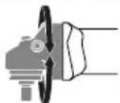
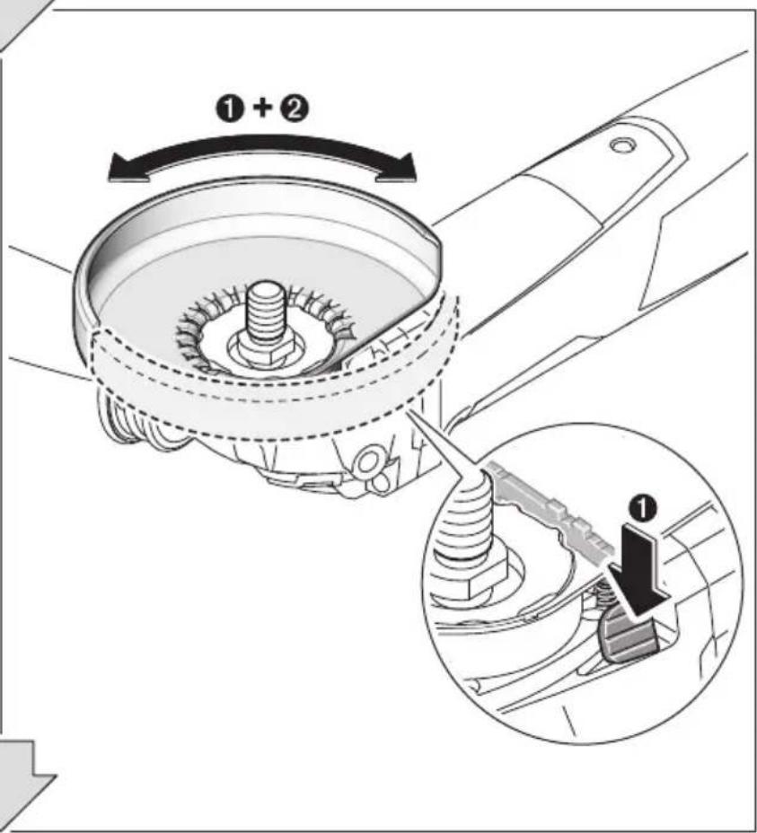
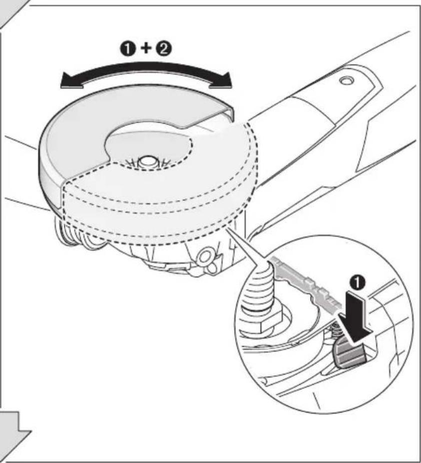
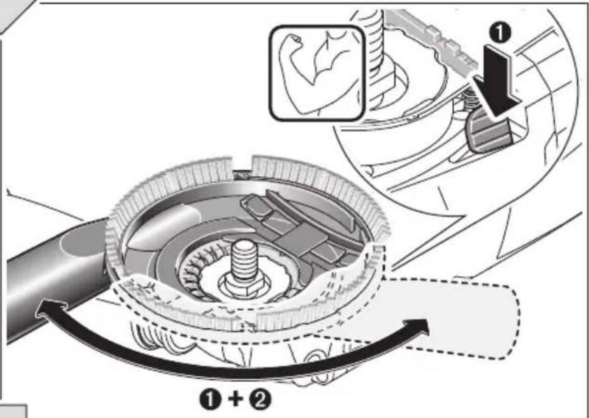
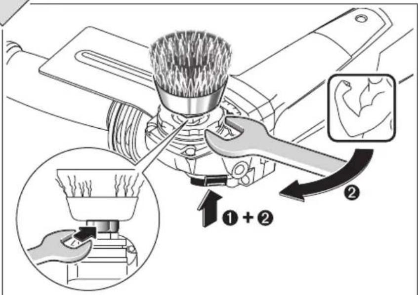
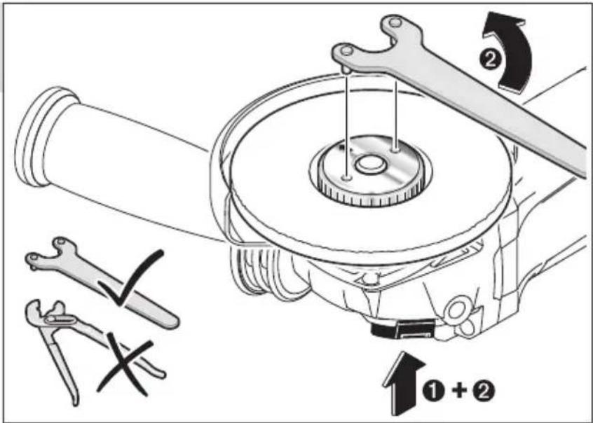
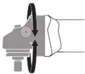
The protection guard may only be turned while actuating the release lever on the gear head. Otherwise, the machine may not continue to be used anymore and must be sent to an after-sales service agent.
▶ Do not touch grinding and cutting discs before they have cooled down. The discs can become very hot while working.
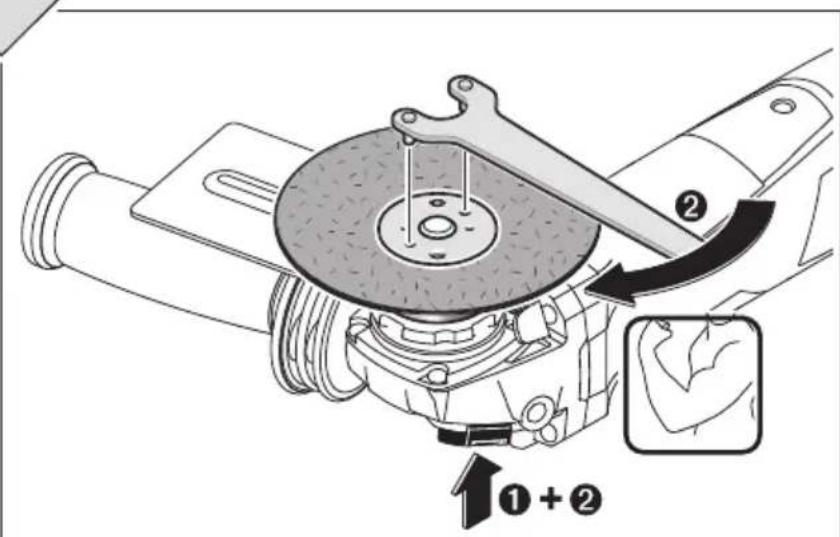
▶ Actuate the spindle lock button only when the grinder spindle is at a standstill. Otherwise, the machine may become damaged.
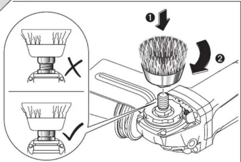
▶ After mounting the grinding tool and before switching on, check that the grinding tool is correctly mounted and that it can turn freely. Make sure that the grinding tool does not graze against the protection guard or other parts.
▶ When operating the machine with power from mobile generators, loss of performance or untypical behavior can occur upon switching on.
By applying too high application force, the machine can be subject to overload. Overload can lead to overheating and damage of the power tool. After heavily straining the power tool, continue to run it at no-load for several minutes in order to cool it down.
▶ Do not use the power tool with a cut-off stand.
▶ Never use a cutting disc for roughing.
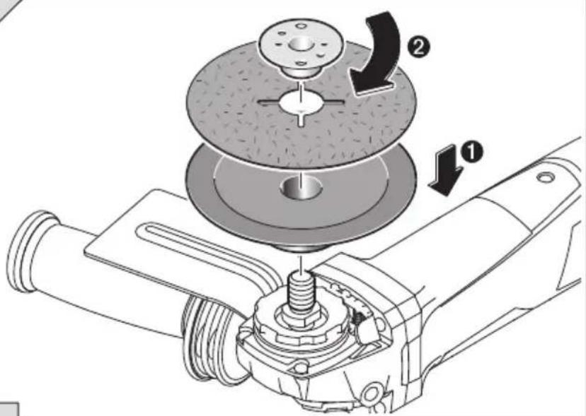
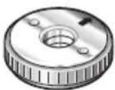
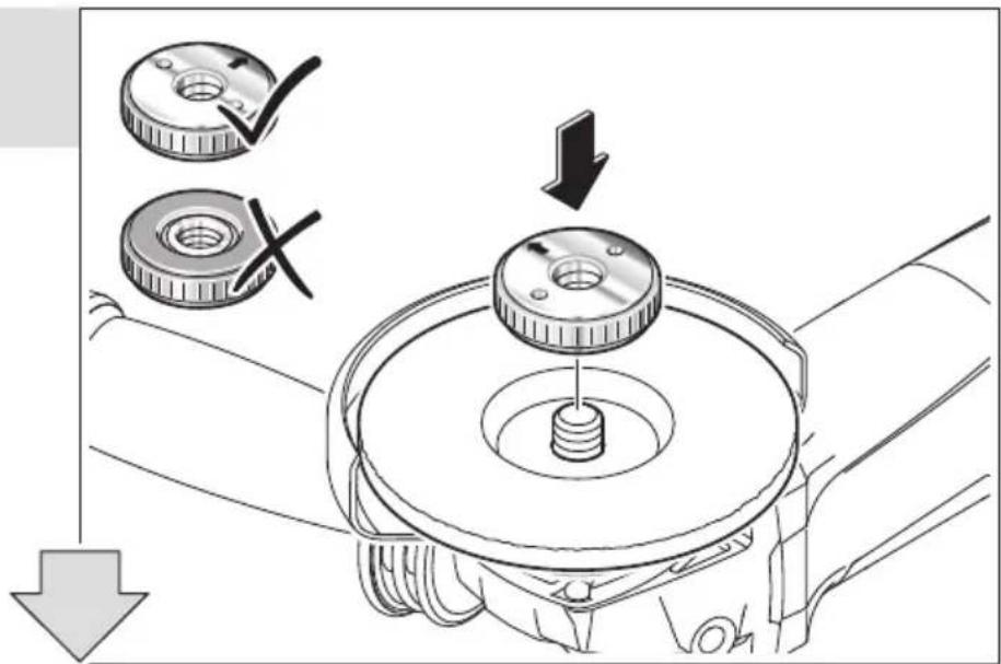
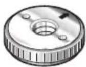
The quick-clamping nut may be used only for grinding or cutting discs. Use only a flawless, undamaged quick-clamping nut.
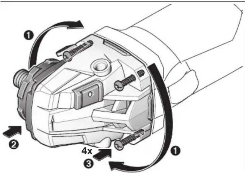
- Do not pull out the gear head while turning it – see figure 12, page 167.
▶ To save energy, only switch the power tool on when using it.
▶ Products sold in GB only: Your product is fitted with a BS 1363/A approved electric plug with internal fuse (ASTA approved to BS 1362).
If the plug is not suitable for your socket outlets, it should be cut off and an appropriate plug fitted in its place by an authorised customer service agent. The replacement plug should have the same fuse rating as the original plug.
The severed plug must be disposed of to avoid a possible shock hazard and should never be inserted into a mains socket elsewhere.
Products sold in AUS and NZ only: Use a residual current device (RCD) with a rated residual current of 30 mA or less.
Symbols
The following symbols are important for reading and understanding the operating instructions.
Please take note of the symbols and their meaning. The correct interpretation of the symbols will help you to use the machine in a better and safer manner.
| Symbol Meaning | |
 | Article number |
 | Read all safety warnings and all instructions |
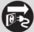
 | Before any work on the machine itself, pull the mains plug from the socket outlet |
 | Wear protective gloves |
 | Always wear ear protection. |
 | Wear safety glasses/goggles |
 | Movement direction |
 | Apply strength for the workstep. |
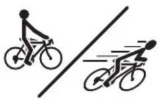
 | Low speed |
 | High speed |
| [K2HD] | Switching On |
 | Switching Off |
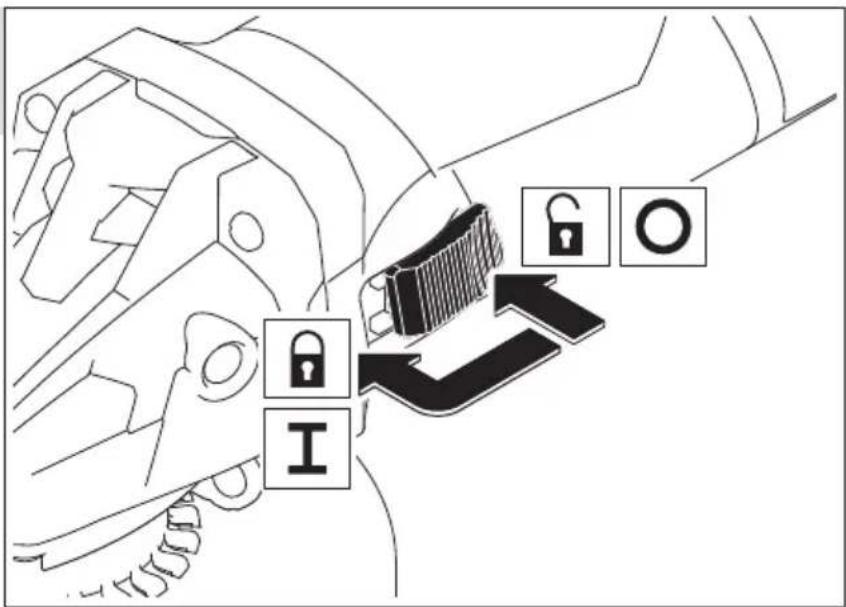
| [02T6] | On/Off switch lock-on |
 | Releasing the lock-on function of the On/Off switch |
 | Prohibited action |
 | Permitted action |
 | Next step of action |
| [00120] | Rated power input |
| [00201] | Output power |
| [00451] | |
| [0428] | Speed control adjustment |
 | I = Grinder spindle length d_1 = Grinder spindle diameter |
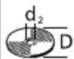 | D = Max. grinding disc diameter d_2 = Inner disc diameter |
 | Speed preselection |
 | Constant Electronic Control |
 | Kickback stop |
 | Restarting ProtectionThe restarting protection feature prevents uncontrolled restarting of the machine after an interruption in the power supply.To restart the operation, switch the On/Off switch to the Off position and start the machine again. |
 | Reduced starting current |
| Symbol Meaning | |
| Additional information | |
| Surface grinding | |
| Grinding/sanding with sandingsheet | |
| Weight according toEPTA-Procedure 01/2003 with vibration-damping auxiliary handle | |
| Weight according toEPTA-Procedure 01/2003 with standard-auxiliary handle | |
| □/II | Symbol for protection class II (completely insulated) |
| L_wA | Sound power level |
| L_pA | Sound pressure level |
| K | U n c |
| a_h | Vibration total value |
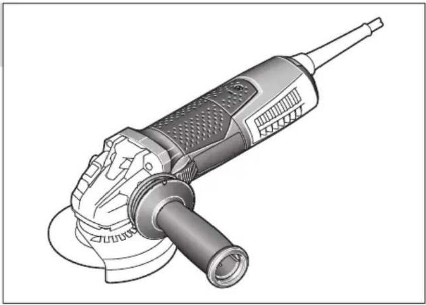
Delivery Scope
Angle grinder, protection guard, auxiliary handle. Special protection guards, application tools and other accessories shown or described are not part of the standard delivery scope.
A complete overview of accessories can be found in our accessories program.
Intended Use
The machine is intended for roughing metal, stone and ceramic materials and for drilling tiles.
For cutting with bonded abrasives, a special cutting guard (accessory) must be used.
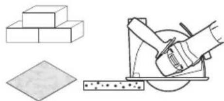
When cutting in stone, provide for sufficient dust extraction.
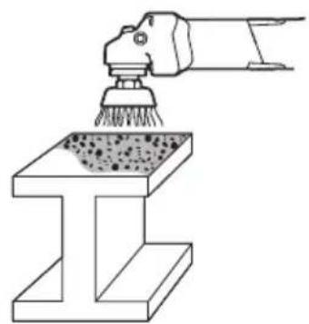
Together with the hand guard (accessory), the machine can be used for brushing and grinding/sanding with elastic sanding plates.
The machine is suitable only for working without water.
Technical Data
The technical data of the machine are listed in the table on page 153.
The values given are valid for a nominal voltage [U] of 230 V. For different voltages and models for specific countries, these values can vary.
Declaration of Conformity €
We declare under our sole responsibility that the product described under “Technical Data” is in conformity with all relevant provisions of the directives 2011/65/EU, until 19 April 2016: 2004/108/EC, from 20 April 2016 on: 2014/30/EU, 2006/42/EC including their amendments and complies with the following standards: EN 60745-1, EN 60745-2-3.
Technical file (2006/42/EC) at: BTI Befestigungstechnik GmbH & Co. KG 74653 Ingelfingen, GERMANY
ppa. Stephan Uder Head of Procurement Department
ppa. Christian Hasenest Head of Business Unit Construction

ppa. Cal U
The measured values of the machine are listed in the table on page 153.
Vibration total values a_h (triax vector sum) and uncertainty K determined according to EN 60745-2-3.
The vibration level given in this information sheet has been measured in accordance with a standardised test given in EN 60745 and may be used to compare one tool with another. It may be used for a preliminary assessment of exposure.
The declared vibration emission level represents the main applications of the tool. However if the tool is used for different applications, with different accessories or insertion tools or is poorly maintained, the vibration emission may differ. This may significantly increase the exposure level over the total working period.
An estimation of the level of exposure to vibration should also take into account the times when the tool is switched off or when it is running but not actually doing the job. This may significantly reduce the exposure level over the total working period. Identify additional safety measures to protect the operator from the effects of vibration such as: maintain the tool and the accessories, keep the hands warm, organisation of work patterns.
Mounting and Operation
The following table indicates the action objectives for mounting and operation of the power tool. The instructions for each action objective are shown aside. Depending on the type of application, various instruction combinations are required. Observe the safety instructions.
Action Figure Please observe Page
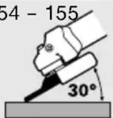
Grinding, preparation 1 154 - 155
Cutting, preparation 2 156


| Action Figure Please observe Page | ||||||
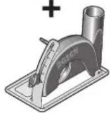
| Cutting stone, brick and tiles, preparation (recommendation) | 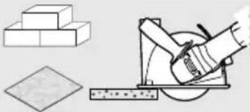 | 3 158 - |  |  | ||
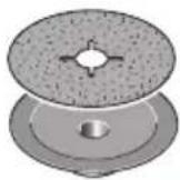
| Sanding with extraction hood, preparation | 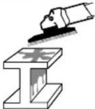 | 4 160 - |  |  | ||
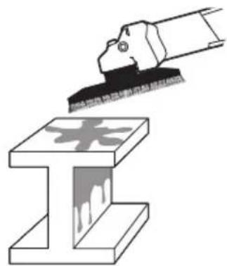
| Removing paint, preparation | 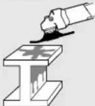 | 5 162 |  |  | ||
| Removing rust, preparation | 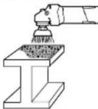 | 6 163 |  |  | ||
| Drilling tiles, preparation | 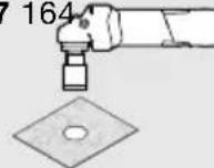 |  |  | |||
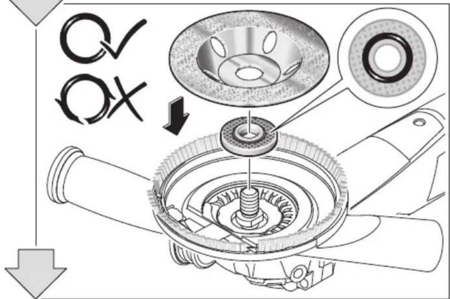
| Mounting the quick-clamping nut | 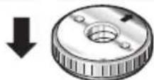 | 8 164 - |  |  | ||
| Dismounting the quick-clamping nut | 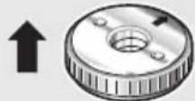 | 9 165 |  |  | ||
| Switching On and Off 10 |  |  |  | |||
| Adjusting the speed preselection |  | 11 166 | ||||
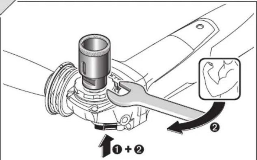
| Rotating the Machine Head |  | 12 167 |  |  | ||
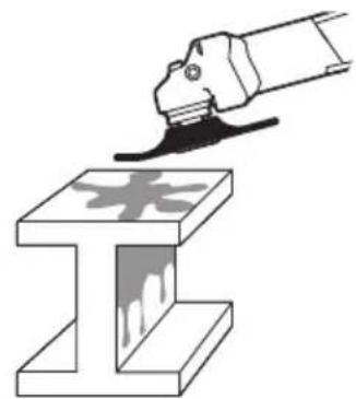
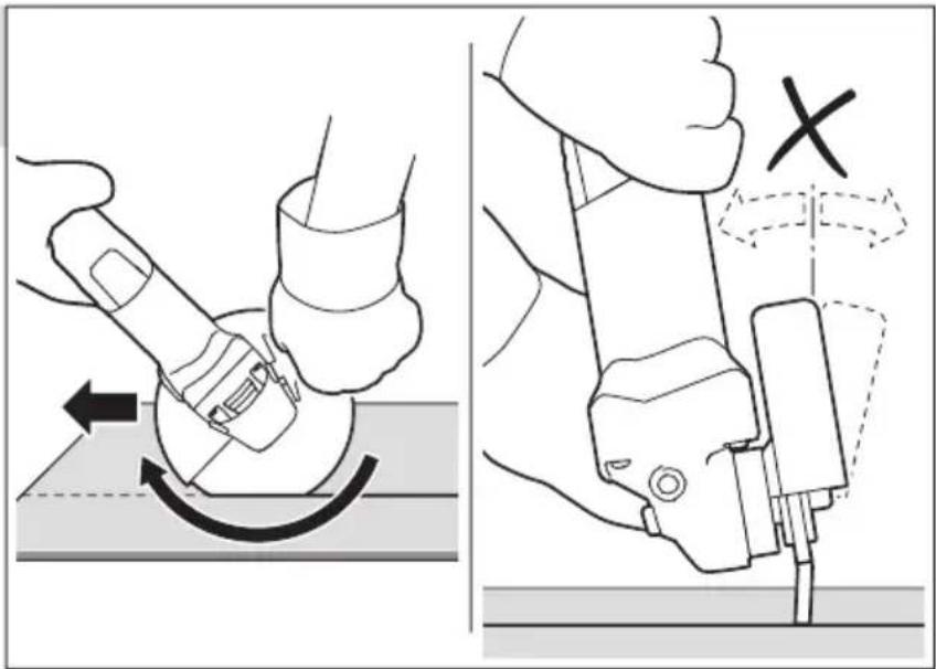
| Working effectively with the angle grinder |  | 13 168 |  | |||
Action Figure Please observe Page
Grey-marked area: Handle (insulated gripping surface)
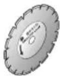
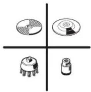
Selecting the admissible grinding tool
text_image
i+14 168
15 169
Maintenance and Cleaning
For safe and proper working, always keep the machine and ventilation slots clean.
In extreme conditions, always use dust extraction as far as possible. Blow out ventilation slots frequently and install a portable residual current device (PRCD). When working metals, conductive dust can settle in the interior of the power tool. The total insulation of the power tool can be impaired.
Please store and handle the accessory(-ies) carefully.
If the replacement of the supply cord is necessary, this has to be done by BTI or an authorized BTI service agent in order to avoid a safety hazard.
In all correspondence and spare parts orders, please always include the 7-digit order number given on the nameplate of the machine.
Disposal
The machine, accessories and packaging should be sorted for environmental-friendly recycling.
Only for EC countries:
According to the European Directive 2012/19/EU for Waste Electrical and Electronic Equipment and its implementation into national right, power tools that are no longer usable must
be collected separately and disposed of in an environmentally correct manner.
Subject to change without notice.
Head of Business Unit
Construction

text_image
papia hui
Head of Business Unit
Construction

text_image
papia AHL
text_image
ppa. Paul Wnatural_image
Illustration of a hand using a tool to cut a block, with another block and ruler nearby (no text or symbols)natural_image
Illustration of a hand using a tool to mark the I-beam symbol, with no visible text or labels.natural_image
Illustration of a hand using a tool to shape an I-beam with a currency symbol (no text or labels)1 154 -

2 156 -

3 158 -

4 160 -

5 162

ppa. Stephan Uder Head of Procurement Department
ppa. Christian Hasenest Head of Business Unit Construction

text_image
pap a h l oppa. Carl W
ppa. Stephan Uder Head of Procurement Department
ppa. Christian Hasenest Head of Business Unit Construction


ppa. Stephan Uder Head of Procurement Department
ppa. Christian Hasenest Head of Business Unit Construction

text_image
pap a h h c
ppa. Stephan Uder Head of Procurement Department
ppa. Christian Hasenest Head of Business Unit Construction

text_image
pap a h l lppa. Carl W
natural_image
Two cyclists crossing a diagonal line, one on the left and one on the right (no text or symbols)ppa. Stephan Uder Head of Procurement Department
ppa. Christian Hasenest Head of Business Unit Construction

text_image
papia AHLppa. Cal U
ppa. Stephan Uder Head of Procurement Department
ppa. Christian Hasenest Head of Business Unit Construction


ppa. Stephan Uder Head of Procurement Department
ppa. Christian Hasenest Head of Business Unit Construction

text_image
ppa. U ppa. C## Uppa. Stephan Uder Head of Procurement Department
ppa. Christian Hasenest Head of Business Unit Construction

text_image
papa huippa. Carl W
ppa. Stephan Uder Head of Procurement Department
ppa. Christian Hasenest Head of Business Unit Construction

text_image
ppa.## ppa.##natural_image
Silhouette of two cyclists crossing a diagonal line (no text or symbols)text_image
Technical diagram illustrating mechanical assembly steps with numbered components and directional arrows indicating motion
text_image
① + ② ①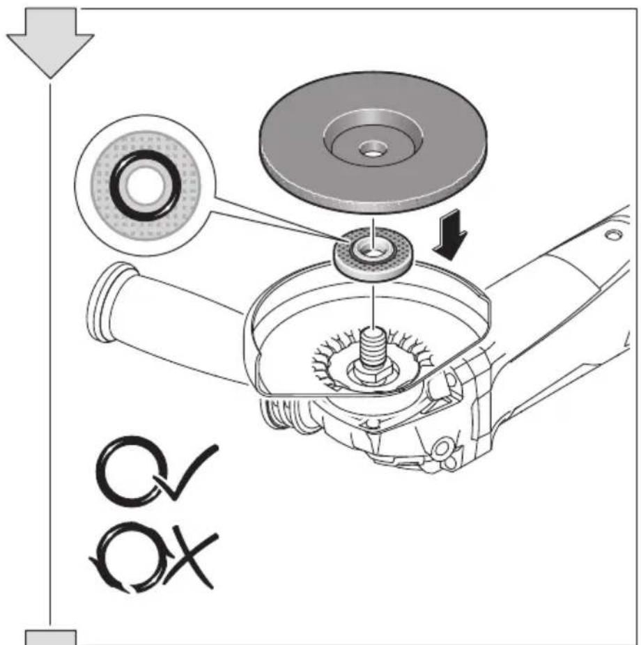
text_image
Technical diagram illustrating the assembly of a mechanical component with labeled parts and directional arrows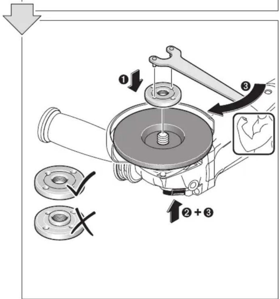
text_image
Technical diagram illustrating mechanical assembly steps with numbered instructions and labeled components2

natural_image
Simple line drawing of a mechanical component with no text or symbols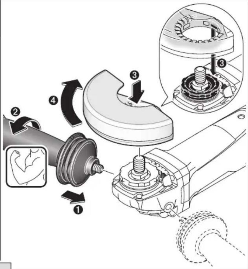
text_image
Technical diagram illustrating mechanical assembly steps with numbered components and directional arrows indicating motion.
text_image
① + ② ①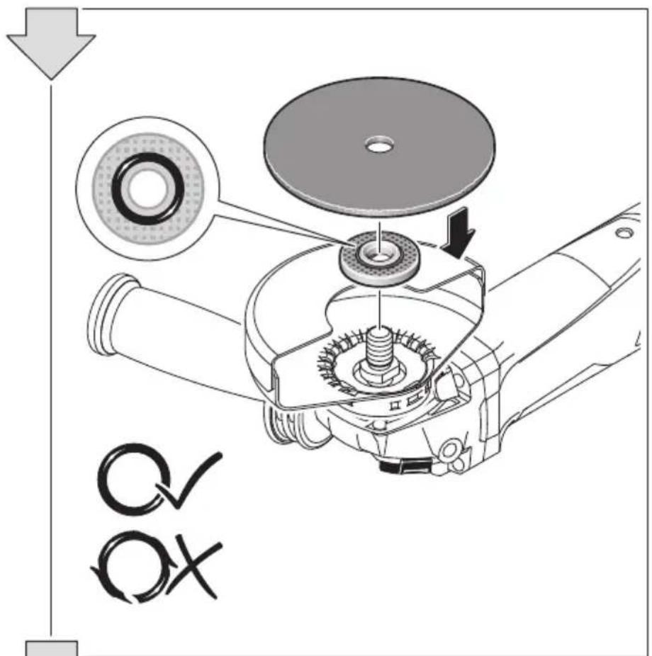
text_image
Technical diagram of a mechanical assembly with labeled parts and directional arrows, including a magnified view of the component.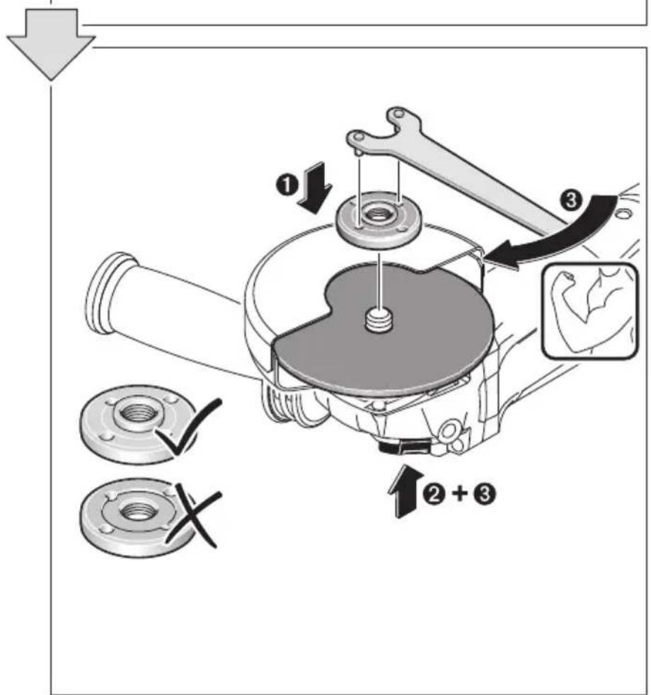
text_image
Technical diagram illustrating mechanical assembly steps with labeled components and directional arrows3

natural_image
Illustration of geometric construction steps: stacked blocks, a diamond, and a hand using a tool on a circular base (no text or symbols)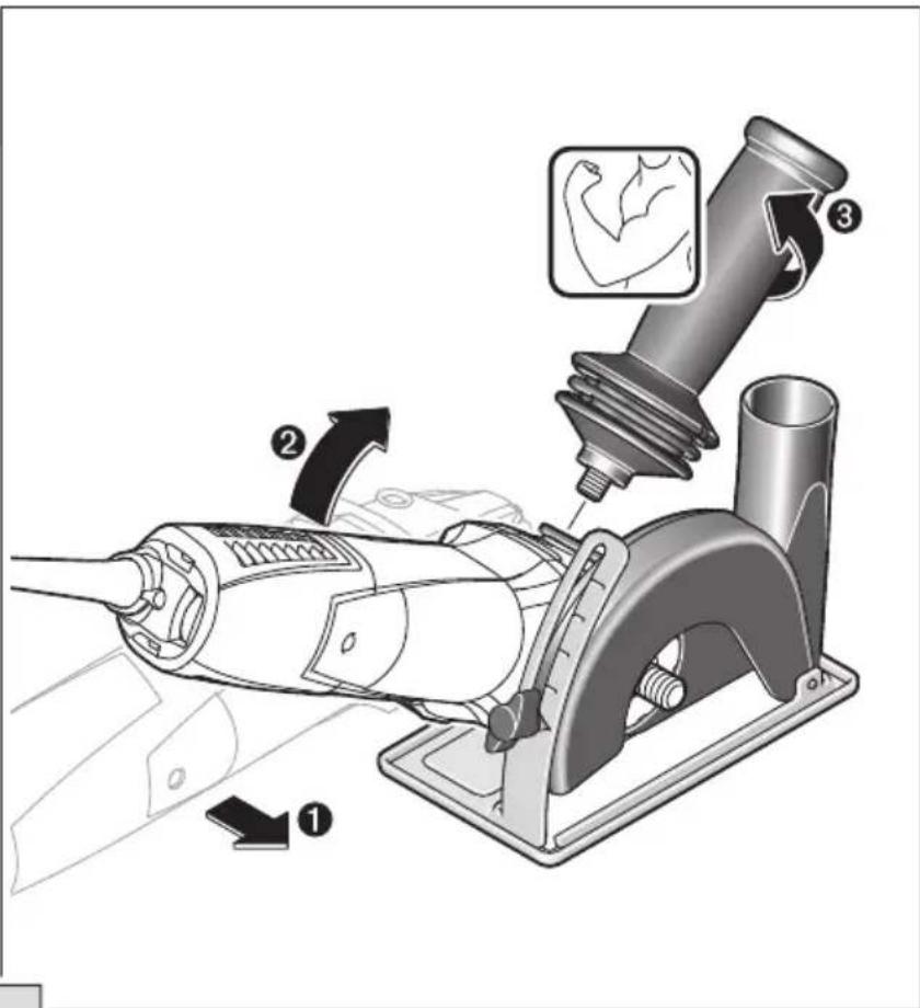
text_image
Diagram illustrating a robotic arm tool with labeled parts and motion arrows, showing movement from tool to arm and grip.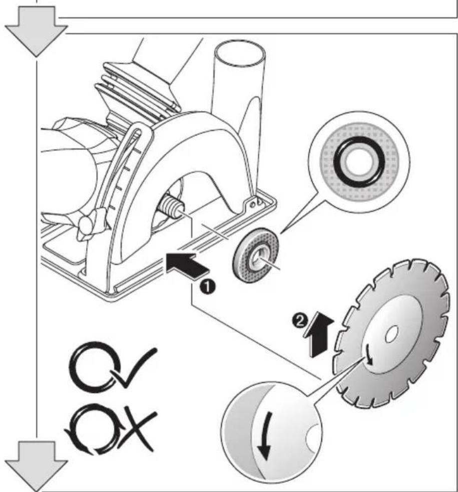
text_image
Technical diagram illustrating the mechanical assembly of a lathe machine, showing gear and wheel components with labeled parts.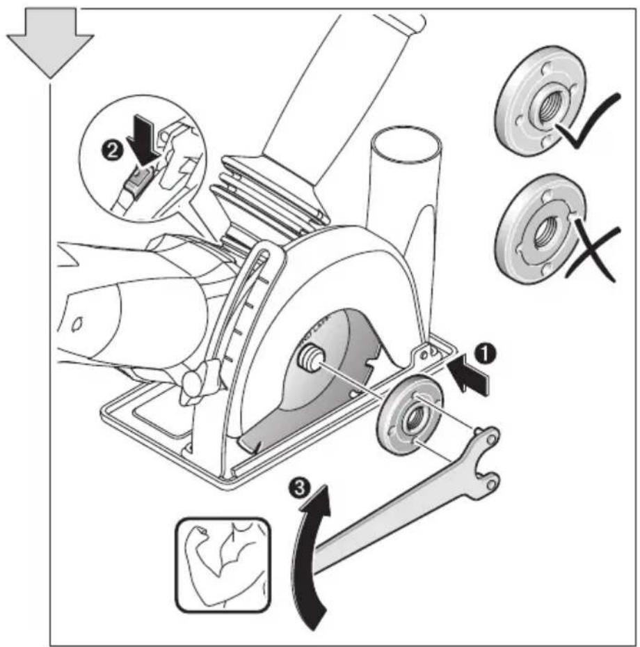
text_image
Technical diagram illustrating mechanical assembly steps with labeled components and directional arrows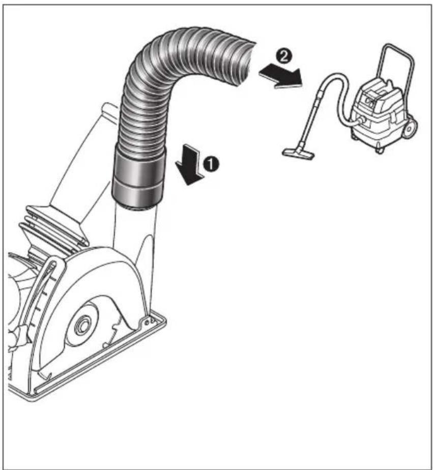
text_image
Diagram showing a vacuum cleaner with labeled parts and directional arrows indicating components.4

natural_image
Illustration of a hand using a tool to cut a metallic object into a I-beam (no text or symbols present)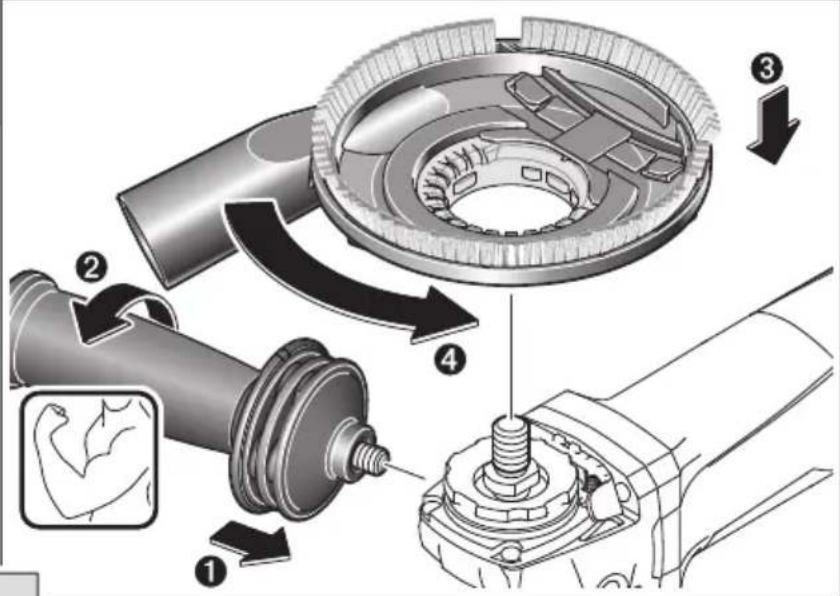
text_image
Technical diagram illustrating mechanical assembly steps with numbered components and directional arrows indicating motion
text_image
Technical diagram illustrating mechanical assembly with labeled parts and directional arrows, including a magnified inset of the arm mechanism.
text_image
Technical diagram illustrating the assembly of a mechanical component with labeled parts and directional arrows indicating process flow.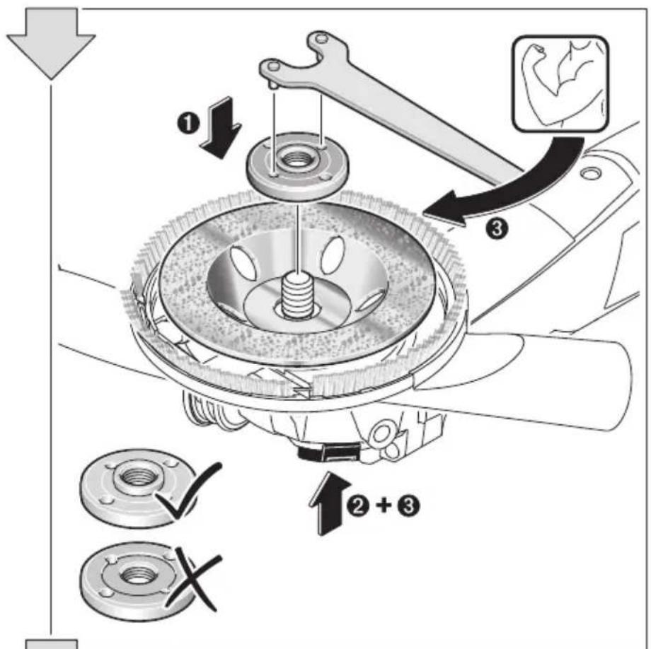
text_image
Mechanical assembly diagram showing gear and wrench components with numbered annotations and directional arrows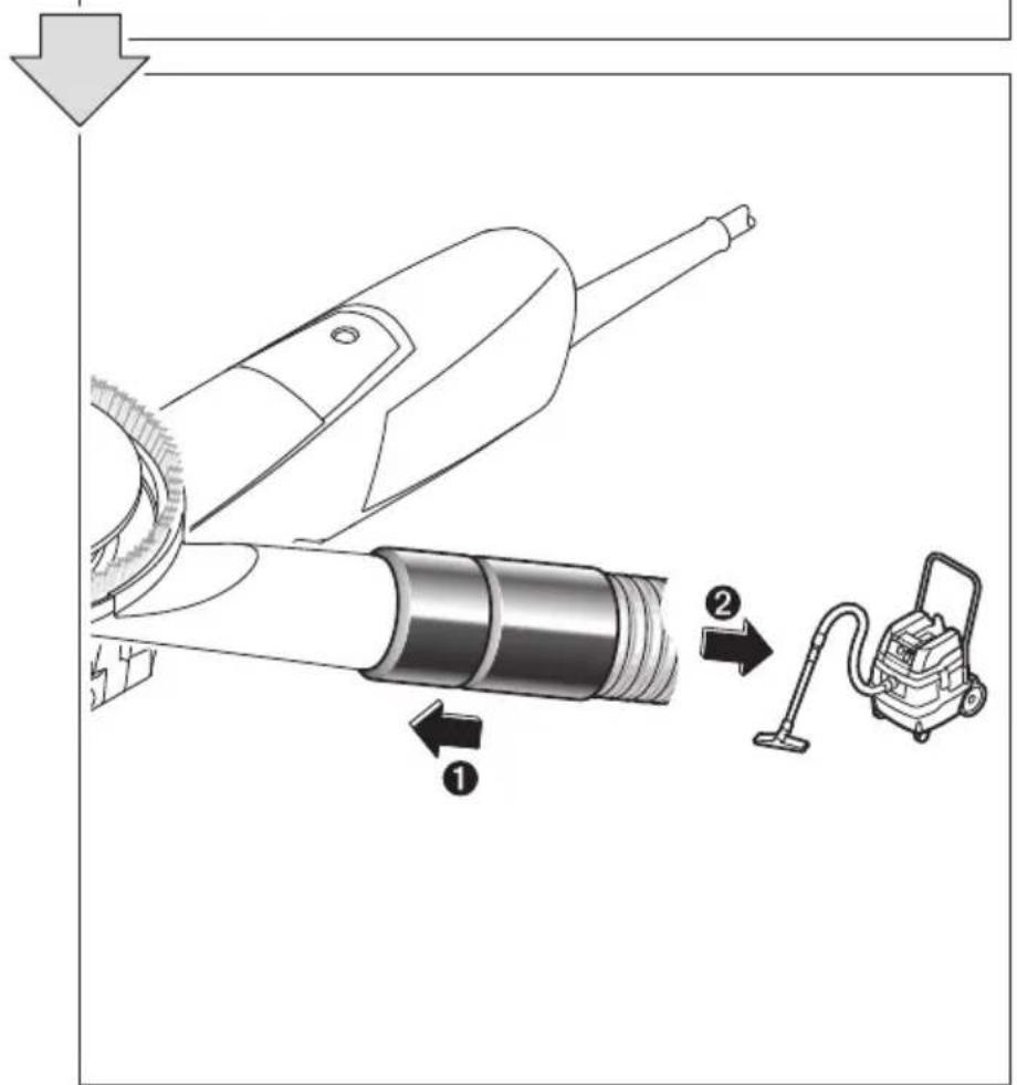
text_image
Diagram illustrating the process of a vacuum cleaner with labeled components and directional arrows5

natural_image
Illustration of a hand painting a stylized I-beam with a star symbol on the base (no text or symbols present)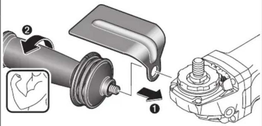
text_image
Technical diagram illustrating mechanical assembly steps with labeled components and directional arrows
text_image
Technical diagram of a mechanical assembly with labeled components and directional arrows indicating motion or movement.
text_image
Technical diagram showing mechanical assembly with labeled parts and directional arrows indicating motion or movement6

natural_image
Diagram of a robotic arm spraying particles onto a 3D I-beam structure (no text or symbols)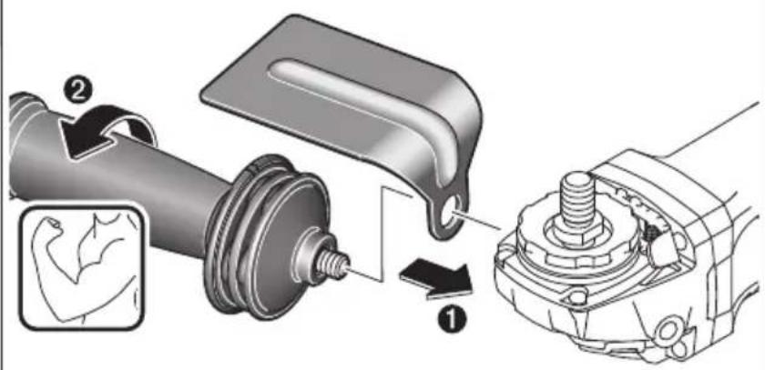
text_image
Technical diagram illustrating mechanical assembly steps with labeled components and directional arrows
text_image
Diagram illustrating a hairbrushing process with labeled steps and tool illustrations
text_image
Diagram illustrating hair styling technique with labeled steps ① and ②, showing brush manipulation and arm placement.7

natural_image
Diagram of a robotic arm interacting with a square plate (no text or symbols)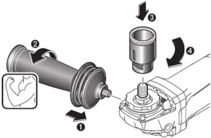
text_image
Technical diagram illustrating mechanical assembly steps with numbered components and directional arrows indicating motion.
text_image
Technical diagram showing mechanical assembly with labeled parts and directional arrows indicating movement or force direction8


text_image
Technical diagram showing mechanical assembly with labeled parts and directional arrows indicating motion or assembly steps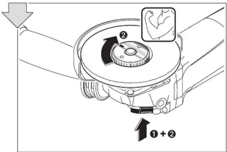
text_image
Diagram illustrating mechanical assembly with labeled parts and directional arrows, including a magnified inset showing arm muscle.9

↑
text_image
Technical diagram illustrating mechanical assembly with labeled parts and directional arrows indicating motion or assembly.10


text_image
Diagram showing mechanical component with lock and switch symbols, indicating a lock function or repair operation.11
natural_image
Two bicycle riding scenarios separated by a diagonal line (no text or symbols)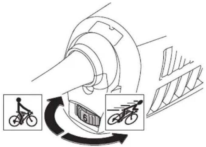
text_image
Diagram illustrating bicycle laneing and laneing process with labeled components and directional arrows


natural_image
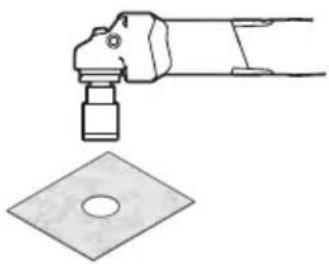
Mechanical part diagram showing a Bosch tool with a cylindrical shaft and base plate (no text or symbols)


12

natural_image
Pure mechanical component diagram without any text, numbers, or symbols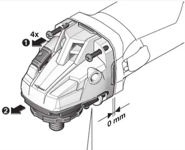
text_image
4x ① ② 0 mm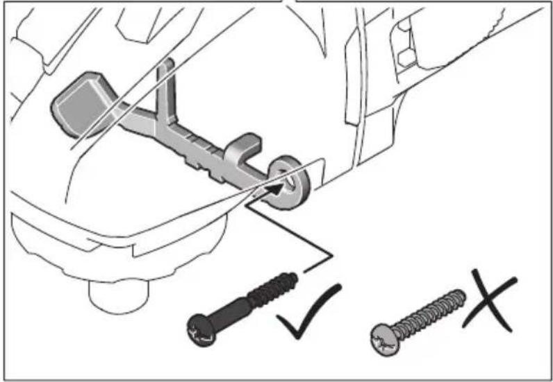
natural_image
Technical illustration of a car's seat assembly with screw and nut components (no text or symbols)
text_image
Technical diagram of a mechanical component with numbered parts and directional arrows indicating motion or assembly.13


text_image
Technical diagram illustrating a mechanical tool manipulation technique with labeled components and directional arrows14

natural_image
Technical illustration of a mechanical power tool with a circular base and radial blade (no text or symbols)15
natural_image
Four schematic diagrams of electronic components arranged in a cross pattern (no text or labels)| max. [mm] [mm] D b d [min] | -1] | [m] | |||
| b | 115 7 | 22,2 | 11500 | 80 | |
| 125 7 | 22,2 | 11500 | 80 | ||
| 150 7 | 22,2 9 | 300 | 80 | ||
| D | 115 | - | - | 11500 | 80 |
| 125 | - | - | 11500 | 80 | |
| b | 75 30 M 14 11500 | 45 | |||
| D | 82 M 14 11500 80 | ||||